1
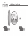
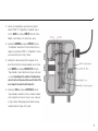
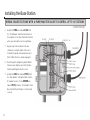
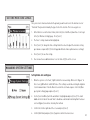
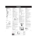
Installation and User Manual UgMO Technologies• 840 First, Suite 300 • King of Prussia, PA 19406 • www.UgMO.com Please leave with property owner Installation and User Manual UgMO™ monitors soil moisture in the root zones of your UgMO wireless sensors have a patented electronic plants, limiting watering by your irrigation controller to moisture sensing circuit and low power radio signal. avoid over-watering. UgMO consists of two components, Two uniquely configured batteries (supplied and the UgMO Wireless Sensor and the UgMO Base Station. installed) provide an operating life of up to 5 years. Up to 24 wireless sensors can be paired, assigned and The UgMO Base Station is powered by your Irrigation buried to control up to 6 watering zones (valves). controller. The Base Station is wired between any common elec- Installation requires only basic electrical tools (a wire tronic irrigation controller (sometimes called a ‘clock’), stripper, crimper, connectors) a thin flat screwdriver, and the valves controlling watering in up to six zones. drywall screws, a Philip head screwdriver for mounting UgMO supports the control of a Master Valve or Pump and an AC voltmeter (Digital MultiMeter). UgMO devices via a special output. are weather resistant for outdoor use. Wireless Sensors UgMO saves water and improves plant health by limiting are buried at depths from 1” to 4” overwatering for lawns and ornamental plantings. according to plant and soil types and operate at Irrigation controllers can be set according to the hottest distances up to 600 feet, depending on soil type, depth, or driest conditions expected. UgMO limits watering to and line of site to the Base Station. UgMO is easy to in- be ‘just enough’. stall, effective and long lasting. It is not uncommon for a typical home to reduce water use by as much as 45%. Table of Contents I N STA L L AT I O N A N D U S E R M A N UA L Components ..................................................................................................................................................... 2 Preparing to Install .......................................................................................................................................... 4 Site Assessment ............................................................................................................................................... 5 Installing the Base Station .............................................................................................................................. 6 Mounting the Base Station .................................................................................................................... 6 Wiring a Single Base Station ................................................................................................................. 7 Determining AC Polarity of Existing Irrigation Clock ........................................................................ 10 Wiring 2 Base Stations with a Pump/Master Valve to Control Up to 12 Stations ............................. 11 Base Station User Interface........................................................................................................................... 14 Main Screen ......................................................................................................................................... 14 Auto/Bypass Indicator................................................................................................................. 15 Pump/Master Valve Indicator ..................................................................................................... 15 Water Savings Indicator .............................................................................................................. 15 Zone Control Indicator ................................................................................................................ 15 Zone Moisture Level Indicator .................................................................................................... 16 Battery and Wireless Strength Indicator .................................................................................... 17 Set Contrast ......................................................................................................................................... 17 Manage Sensors .................................................................................................................................. 18 Pairing sensors to Base Station: Choosing Sensors.................................................................. 18 Assigning a Common Sensor ..................................................................................................... 20 Assigning More than one Sensor to a Zone ................................................................................ 21 Assigning a Sensor to More Than One Zone .............................................................................. 21 Pairing Sensors to Base Station: Manual Entry ......................................................................... 22 Setting Moisture Levels....................................................................................................................... 23 Manage System Settings ..................................................................................................................... 23 Setting Auto and Bypass ............................................................................................................. 23 Setting Global Cold Temperature Override ................................................................................ 24 Manage Zone Settings ......................................................................................................................... 25 Zone Bypass Setting ................................................................................................................... 25 Multiple Sensors Per Zone Settings ........................................................................................... 26 View Sensors........................................................................................................................................ 27 Determining Wireless Signal Strength ....................................................................................... 27 Reading the View Sensor Screen................................................................................................ 28 Activating the Archives ............................................................................................................... 29 Installing Sensors .......................................................................................................................................... 30 Placement of Sensors.......................................................................................................................... 32 Completing the Installation................................................................................................................. 34 Appendix A: Troubleshooting Guide .............................................................................................................. 36 Appendix B: Soil Property Field Test ............................................................................................................ 38 Appendix C: Watering Guidelines: Setting the Irrigation Controller for UgMO .......................................... 44 Components UgMO Base Station UgMO Wireless Sensor 1. LCD Screen 2. Power Indicator light 13. Tine: Sensor element that measures moisture level and temperature when exposed to soil 3. 4. Lit when irrigation clock is requesting a valve to water Selection button controls entries highlighted on LCD Screen 5. Connections from Base Station to Irrigation Clock 6. Connections from Base Station to valve wires 7. Cover concealing terminal connections 8. “Wiring Harness”: 18 conductor cable and strain relief leading to irrigation clock 9. Selection wheel 10. Lit when UgMO is allowing watering and zone valve is open 11. Check valve light illuminates when UgMO identifies a wiring short in existing irrigation system 12. Zone numbers corresponding to LCD screen 2 14. Tine sleeve: Protects Tine in shipment and turns sensor on when removed 15. Battery door 13 14 15 3 Preparing to Install Product Verification Check shipped product and confirm that all hardware is present. Required Materials Electrical Connectors: Small supply of assorted electrical connectors and wire nuts. Electrical Tape: Assorted colors Wire Labels: To clearly mark all wires in the irrigation clock. Wire Ties Wire Tacks: to secure any loose wires to mounting structure. Silicone: For water-tight seal of wiring harness strain relief connection to clock. Mounting Screws: To mount brackets to wall. UgMO Base Station UgMO Wireless Sensor Required Tools Digital Multi-meter: Also known as a Voltmeter. Required to test AC polarity and confirm proper wiring. Screwdriver: Phillips #1, #2 and small electrical screwdrivers for tightening terminals. Cordless Drill/Bits: For drilling holes for mounting screws. 1¹⁄ΛΠ” Hole Saw Bit: For drilling a hole into the irrigation clock Wire Strippers, Side Cutters and Crimpers: Necessary to install Base Station Shovel or Hole Cutter: For digging holes for placement of sensors. 1.25 inch Putty Knife: Or something similar for cutting slot in soil for tine insertion. 10 Inch Crescent Wrench or Channel Locks: To tighten strain relief nut. Tape Measure: To measure sensor location. UgMO Soil Press: To determine soil type. Irrigation Flags: To mark sensor locations. 4 Mounting Bracket Yellow Whisker Marker One per Sensor Site Assessment Site Survey 1. Visually inspect the property, location of clock and placement of the Base Station. 2. Run all valve stations to: 3. 4. 5. • Confirm zone location and sprinkler count per zone. • Identify areas within each zone to place sensors (rule of thumb is to place the sensors between irrigation sprinklers, in an area that tends to be the driest and where you have the best line of sight to the Base Station with the least obstructions. Generally high spots are the driest and low lying areas should be avoided). • Identify any operating issues with the clock, valves and/or sprinklers. Note different types of hardware • Drip irrigation • Rotor Heads • Spray Heads Note different types of zone plantings • Turf • Shrubs and woody plants • Annuals and Perennial flowers Record all start times, cycle run times and programmed run days. 5 Installing the Base Station MOUNTING THE BASE STATION 1. 6 Choose the location of the UgMO Base Station following these guide lines: • Base Station needs to be 12-18 inches away from and higher than the irrigation clock. • Base Station should be within 600 feet of any possible sensor location. • Base Station should not be mounted near or on the same plane as large metal objects or high voltage transformers. • When installing two Base Stations, place them at least 10 inches apart. 2. After locating the optimum location for the UgMO Base Station, use the Base Station Bracket mounting plate as a template to mark the drilling locations. 3. Drill two holes (small pilot holes if mounting to a solid material like wood or larger holes to accommodate a drywall, stucco or concrete alligator anchor). Tapcon screws are also an option. 4. Secure the mounting plate to the wall. 5. Insert the Bracket Arm into the Bracket Adaptor on the rear of the Base Station. Tighten with provided Allen wrench. 6. Using the provided Allen wrench attach the Bracket Arm to the mounting plate. 7. Rotate bracket arm so that the hinge allows for side-to-side movement- not up and down. WIRING A SINGLE BASE STATION IMPORTANT NOTE: Determine if the irrigation system uses a pump or Master Valve. Look at the irrigation wiring, if there is a wire attached to a terminal labeled “P/MV” or “Pump/Master Valve”, the system has one of these present. IMPORTANT NOTE: DO NOT ATTACH THE POWER CONDUCTORS UNTIL ALL OTHER WIRES HAVE BEEN ATTACHED 1. Using wire labels, label all valve stations, common, power and pump master (if present) wires in the irrigation clock. 2. Using a 1¹⁄ΛΠ” hole saw bit, drill a 1¹⁄ΛΠ” hole into the irrigation clock on the side nearest the Base Station making sure that no internal parts are damaged. Remove any internal electronic boards that may be in the way of the drilling procedure. The irrigation clock may be outfitted with a punch out also though keep in mind most punch outs are only ¾ of inch in size. 3. 4. Remove the jam nut from the wire strain relief and carefully insert the 18 conductor wiring harness from the Base Station into the irrigation clock through the one inch hole. Thread the wires from the wiring harness through the wire strain relief nut inside the irrigation clock and insert and secure the male end of the wire strain relief by screwing the jam nut on. The wiring harness wires will be bundled into three groups (“Clock Bundle”, “Valve Bundle”, “Power Bundle”) and each wire in the bundles individually labeled as well. 5. Identify the wires in the irrigation clock that go to each valve station. Remove the wire (in the irrigation clock) from the Valve Station #1 terminal and butt connect it to the WHITE wire with a BLUE STRIPE labeled V1/V7 and crimp it so its attached securely. 6. Identify the BLUE wire labeled C1/C7 and attach that wire in the irrigation clock’s Valve Station #1 terminal where you removed the wire in step 5 above. 7 Installing the Base Station WIRING A SINGLE BASE STATION (CONTINUED) 7. Remove the wire (in the irrigation clock) from the Valve Station #2 terminal and butt connect it to the WHITE wire with a RED STRIPE labeled V2/V8 and crimp it so its attached securely. 8. Identify the PINK wire labeled C2/C8 from the “Clock Bundle” and attach that wire in the irrigation clock’s Valve Station #2 terminal where you removed the wire in step 7 above. 9. Repeat steps 5 thru 8 above for all valve station wires using the labels on the wires to identify the proper station and valve wires (Refer to the Wire Reference Guide to the right for the proper wire connections). This guide is also provided as a convenient sticker for inside the irrigation clock for easy reference. 10. If you identify that the irrigation clock has a Pump Relay and/or Master Valve proceed to step 11. If not proceed to step 13. 8 11. Remove the Pump Master wire from the terminal labeled “P/MV” or “Pump Master” and butt connect it to the GRAY wire labeled P/M (V), from the “Valve Bundle”, and crimp it so it’s attached securely. 12. Identify the BROWN wire labeled P/M (C) from the “Clock Bundle” and attach it to the terminal in the irrigation clock labeled “P/MV” or “Pump Master” where you removed the wire in step 11 above. 13. Identify the common wire(s) in the irrigation clock, detach them from the terminal and butt connect them to the WHITE wire labeled COM OUT (V), from the “Power Bundle”, and crimp them so they are attached securely. Depending on the number of common wires present a wire nut may need to be used to twist all the wires together instead of a butt connector. 14. Identify the TAN wire labeled COM IN (C) from the “Power Bundle” and attach it to the common terminal on the irrigation clock where the wires were removed in step 13 above. When properly installed the wiring should look like the figure to the right. 9 Installing the Base Station DETERMINING AC POLARITY OF EXISTING IRRIGATION CLOCK 1. Open the wiring compartment of the irrigation clock. 2. Set the Voltmeter to “AC Volts”, sometimes “~V”. Units will be in Volt-AC, often “VAC”. 3. 4. Place the BLACK lead from the voltmeter on the irrigation clock COM terminal. Place the RED lead from the voltmeter on one of the irrigation clock’s AC terminals. 5. If the voltmeter registers 24-30V, this is the (AC +) terminals. 6. If the voltmeter registers ~0V this is the the (AC -) terminals. 10 7. 8. 9. Attach the BLACK wire from the wiring harness “Power Bundle” to the (AC -) terminal. Attach the RED wire from the base station wiring harness to the (AC +) terminal. That’s it! The wiring phase of installation is over. Now it’s time to check your work to be sure that you can control each valve. 10. On a simple installation, like this one, you can simply turn on power, then sequence the Irrigation Controller to manually power each zone. Confirm that each zone turns on, and then turns off, as expected. If so, the wiring is correct. IMPORTANT NOTE: The correct polarity of the AC connection is critical: INCORRECT AC WIRING CAN POTENTIALLY DAMAGE THE BASE STATION AND INVALIDATE THE WARRANTY Use of a Digital Multi-meter (Voltmeter) is required to ensure proper installation. WIRING 2 BASE STATIONS WITH A PUMP/MASTER VALVE TO CONTROL UP TO 12 STATIONS 1. 2. 3. Drill two 1¹⁄ΛΠ” holes in the irrigation controller to allow easy insertion of the Base Station wiring harness, keeping in mind the two Base Stations should be mounted at least 10 inches apart and 12-18 inches away from and higher than the irrigation clock. 4. Using wire labels, label all valve stations, COM, AC, and P/MV (if present) wires in the irrigation clock. 5. Identify the wires in the irrigation clock that go to each valve station. Remove the wire (in the irrigation clock) from the Valve Station #1 terminal and butt connect it to the WHITE wire with a BLUE STRIPE labeled V1/ V7, from the wiring harness “Valve Bundle”, and crimp it so its attached securely. Identify the BLUE wire from the “Clock Bundle” labeled IMPORTANT NOTE: Determine if the irrigation system uses a pump or master valve. Look at the irrigation wiring, if there is a wire attached to a post labeled “P/MV” or “Pump/Master Valve”, the system has one of these present. C1/C7 and attached that wire in the irrigation clock’s Valve Station #1 terminal where you removed the wire in step 3 above. Remove the wire (in the irrigation clock) from the Valve Station #2 terminal and butt connect it to the WHITE wire with a RED STRIPE labeled V2/V8, from the “Valve Bundle”, and crimp it so it is attached securely. IMPORTANT NOTE: DO NOT ATTACH THE POWER CONDUCTORS UNTIL ALL OTHER WIRES HAVE BEEN ATTACHED IMPORTANT NOTE: Systems that use a pump or master valve are cooled by water passing through them. If the P/MV is not connected correctly, over heating may occur and serious damage could result - including pump or valve failure. 11 Installing the Base Station WIRING 2 BASE STATIONS WITH A PUMP/MASTER VALVE TO CONTROL UP TO 12 STATIONS (CONTINUED) 6. Identify the PINK wire labeled C2/C8 from the “Clock Bundle” and attached that wire in the irrigation clock’s Valve Station #2 terminal where you removed the wire in step 5 above. 7. Repeat steps 3 thru 6 above for all valve station wires using the labels on the wires to identify the proper station and valve wires (Refer to Wire Reference Guide on page 8). 8. Next hook up the Pump Relay and/or Master Valve by connecting the wires from the Base Stations and Irrigation Clock in series. 9. Identify the GRAY wire labeled PM (V), from the “Valve Bundle” coming from Base Station #1 and butt connect it to the BROWN wire labeled PM (C), from the “Clock Bundle” from Base Station #2 and crimp it so it is attached securely. 12 10. Remove the Pump Master wire from the terminal (in the irrigation clock) labeled “P/MV” or “Pump Master” and butt connect it to the GRAY wire labeled P/MV (V), from the “Valve Bundle” coming from Base Station #2 (controlling valve stations 7-12). 11. Identify the BROWN wire labeled P/MV (C) from the “Clock Bundle”, coming from Base Station #1 and attached it to the terminal in the irrigation clock labeled “P/MV” or “Pump Master” where you removed the wire in step 10 above. 12. Identify the common wires in the irrigation clock and detach them from the terminal. Using a wire nut, attach them securely to the WHITE wires from both base stations labeled COM OUT (V). Attach the TAN COM IN (C) wires from both base stations to the clock COM terminal. 13. Finally, connect the AC power according to the directions on page 10 to ensure proper polarity. Ensure that both RED wires are connected to the same terminal and both BLACK wires are connected to the same terminal. 13 Base Station User Interface MAIN SCREEN 1. On power-up, you’ll see the Introduction Screen. This times out after 10 seconds, or press the Select Button (#4 on page 2) to display the Main Screen. 2. The Main Screen is divided into six main sections identified as A - F on the figure to the right. 14 A Auto/Bypass Indicator Indicates that UgMO is controlling the watering Indicates that the UgMO system is being bypassed and the clock controls the watering. This is useful for when you want to turn on a zone manually for maintenance or to water in new plantings.. B Pump/Master Valve Indicator If the irrigation system has a Pump or Master Valve, this symbol will flash to indicate that the Pump or Master Valve is operating when a zone is turned on. This area flashes “ON” whenever UgMO allows a zone to come on regardless of the presence of a Pump or Master Valve. C Water Savings Indicator D Zone Control Indicator Displays a calculation of the average time UgMO did not allow the irrigation clock to water. In this example, UgMO reduced the total watering time by 33% since the system was last restarted. There are six columns representing each zone controlled by UgMO (1-6) Indicates the zone is controlled by one sensor Indicates the zone is controlled by more than one sensor Indicates the zone is being controlled by the “Common Sensor” 15 Base Station User Interface MAIN SCREEN (CONTINUED) E Zone Moisture Level Indicator Each column indicates the moisture level for its respective zone relative to the moisture level threshold setting. Indicates that the present moisture level for this zone is within the programed UgMO moisture levels and only the amount of watering required to remain at this moisture level will be allowed. Indicates that the moisture level is below the programmed UgMO moisture levels and full watering as requested by the irrigation clock will be allowed for this zone. Indicates that the moisture level is above the programmed UgMO moisture levels and no watering will be allowed for this zone. 16 Indicates that the soil temperature is below the programmed temperature setting and no watering will be allowed for this zone. When a zone flashes “OFF”, this indicates that the irrigation clock is requesting water but UgMO is not allowing it. When the zone flashes “ON”, this indicates that the irrigation clock is requesting water and UgMO is allowing it. An empty box within the moisture level indicators will be present during a watering event and remain empty for 30 minutes following the end of the final zone watering request from the irrigation clock. F Battery and Wireless Strength Indicator The bottom row of each column displays the wireless connection and battery strength of each sensor. This indicates that the zone has not been paired to a sensor. All columns will display these “dashes” when the Base Station is first powered on and no sensors have been paired. The black box indicates that the sensor battery has sufficient charge. The full antenna symbol indicates the Base Station is receiving regular signals from the sensor. The empty box indicates a low battery warning. The empty antenna symbol indicates several missed signals from the sensor. These indicate no wireless connection to the sensor. This will appear briefly after a sensor has been paired to a zone until a signal is received. If radio signals have been lost for 4 days or upon reset of the Base Station (hold down [Select] for 3-4 seconds, then release), these symbols will appear. SET CONTRAST Rotating the selection wheel while in the main screen WHILE pressing [Select] will bring up the [Set Contrast] screen. Rotating the wheel will allow adjustment of the screen contrast. This can be helpful in very brightly lit installation locations. Press [Select] and this adjustment will be saved. NOTE: Rotating the wheel while in the main screen will always activate the menu screens discussed below. 17 Base Station User Interface MANAGE SENSORS Wireless Sensors need to be linked (paired) to a Base Station and then assigned to one or more irrigation zones. This is an easy process. Pairing sensors to Base Station: Choosing Sensors 18 1. Read the Network Address (NWA) on the Tine Sleeve or bottom of the wireless sensor. This will be the 8 digit numbers and/or letters following “NWA” on the label. (Example: NWA:100002B3). 2. Rotate the [Selection Wheel] down to the [Manage Sensors] page. 3. When there are no sensors paired, the screen will look like the figure to the left. 4. Press [Select] . The [A] will be highlighted and “Add” will appear. 5. Press [Select]. The following screen will appear. 6. This screen allows you to choose your method of entry. The [Choose Sensor] option will display all of the NWAs that are within range of the base station and allows you to choose the one you want. This is the recommended method. [Manual Entry] allows a network address (NWA) to be entered one character at a time. IMPORTANT NOTE: THE WIRELESS SENSOR TINE SLEEVE The tine sleeve acts as an “ON/OFF” switch when placed on the sensor. Removing it activates the sensor or turns it on. Every time the sensor is turned off and back on, the sensor goes into a rapid transmission mode. It transmit 10 times at 10 second intervals to support pairing. Then, for 100 minutes, transmissions will be at once per minute to support the installation. Finally, at approximately once per 10 minutes after that during regular operation. 7. Navigate to highlight [Choose Sensor] and press [Select]. This screen will be displayed. 8. The NWAs of the sensors the base station hears will be displayed one at a time next to “NWA”. It is best to pair one sensor at a time and replace the tine sleeve when done. 9. Confirm that the NWA of the sensor you just activated is highlighted on the screen. 10. Note that the following menu choices have appeared and you can navigate to them with the [Selection Wheel]: [S] - Save [C] - Clear [B] - Back 11. With the NWA highlighted, press [Select]. The first Zone position is reserved for assigning a “Common Sensor” (See “Assigning Common Sensor” on next page). You can scroll through the zone positions (1-6) to choose the zone to assign the sensor to. (The figure to the left shows the sensor assigned as a Common Sensor and to Zone 2.) 12. Press [Select] and roll the selection wheel up to display the zone number. Press [Select]. IMPORTANT NOTE: 13. Press [Select] again to assign the zone. Normally a Sensor is assigned to one zone, but a single Sensor CAN be assigned to as many as 6 zones on a Base Station (See page 21). SAVE YOUR SETTINGS 14. Navigate to [S] to SAVE this setting. Navigate to “S” to SAVE this setting. Do not choose “X” until you have saved the settings or the sensor will not be paired. 15. It is recommended that you replace the tine sleeve over the tine for now. Write the zone number on the tine sleeve to keep track of its assignment. 16. After saving, you will return to the [Manage Sensors] screen. You can [A] Add another sensor by rotating the selection wheel until the [A] is highlighted and repeat steps 5-15. 17. If you are done pairing all of your sensors, rotate the [Selection Wheel] to the [X] in the upper right corner of the screen and press [Select] to exit the screen. 19 Base Station User Interface MANAGE SENSORS (CONTINUED) Assigning A Common Sensor The system supports the concept of a “Common Sensor” which is designed to ensure the system operates properly even when the wireless signal from a distant sensor is lost. This can be due to a dead battery, temporary interference or reduced range due to heavy rain. With a common sensor assigned, the system will use the data from the Common sensor in the system as a fail-safe until connectivity to the lost sensor is regained. As long as the primary sensor for a zone can be heard, the common sensor data is ignored. COMMON POSITION 20 ZONE POSITION 1. Only one sensor can be assigned as a common sensor at a time. 2. Choose a sensor that is nearest to the base station with a strong wireless signal and a zone that is drier than average. 3. When pairing this sensor, navigate to the common position nearest “Zones:” Press [Select] and rotate the wheel until “C” is shown. Press [Select]. 4. Rotate the wheel to the zone position you wish to assign the sensor to control and press [Select]. Rotate the wheel to reveal the zone number and press [select]. 5. Navigate to [S] to save this setting. 6. If you assign another sensor as the Common, it will automatically remove the Common setting from the previously assigned sensor but maintain any zone assignments for that sensor. Assigning a sensor to more than one zone It is possible to assign a Sensor to more than one zone so that both zones are managed by the data from that sensor. This is usually done when two zones are very similar in the amount of sun or shade they are exposed to. Assigning more than one sensor to one zone It is also possible to assign more than one Sensor to a single zone. That zone can be set to manage the zone to the WETEST sensor reading, DRIEST sensor reading or the AVERAGE reading of all of the sensors assigned to that zone. (See “Manage Zones” settings) Editing an assigned sensor Any assigned sensor, including a common sensor, can be edited by scrolling to [Managing Sensors] and choosing [E] for “Edit”. Scroll to [S] to save your change. 21 Base Station User Interface MANAGE SENSORS (CONTINUED) UgMO allows you to manually pair sensors to a base station. This is particularly helpful if a sensor is already buried in the ground and you are not able to replace the tine sleeve to set it to rapid broadcast. Pairing sensors to Base Station: Manual Entry 1. Choose [Manual Entry] from the [Manage Sensor] page. 2. The first “0” of the NWA will be highlighted. 3. Pressing [Select] will allow you to enter the appropriate NWA digit in this field by rotating the [Selection Wheel] UP for numbers and DOWN for letters. [A] 4. [2] Press [Select] to enter the selection. Rotate the [Selection Wheel] to enter any other nonzero digits. After entering the last digit, the second zone position will be highlighted and you will be able to assign the sensor to the correct zone and/or assign it as a common sensor. BE SURE TO SAVE EACH SENSOR ASSIGNMENT. 22 SETTING MOISTURE LEVELS Once your sensors have been buried in the ground, you will need to enter the moisture level or “threshold” that you determined by the type of soil at the location. This is an easy process. 1. At the Main Screen on the Base Station, rotate the [Selection Wheel] down three clicks to get to the [Set Moisture Settings] page. Press [Select] 2. The Zone 1 setting column will be highlighted. 3. Press [Select] to change this Zone setting. Rotate the wheel to adjust the moisture setting up or down as required (0-9). (Refer to Appendix B to determine optimal wetness settings) 4. Press [Select] to save this setting. 5. You can now choose additional zones to set or rotate to [X] to exit the screen. MANAGING SYSTEM SETTINGS Setting Global Auto and Bypass 1. When the system is set to “Auto”, UgMO controls the zone watering. When set to “Bypass” in this screen, UgMO will not control ANY zones. This setting is useful when testing the irrigation clock in manual mode. From the Main Screen turn the scroll wheel up one click to the [Manage System Settings] page and press [Select]. 2. Use the [Selection Wheel] until the word “Auto” is highlighted and press [Select]. The small bubble on the left side of the word “Auto” should have a dot inside it indicating that it has been selected. (Bypass) can also be chosen by this method. 3. Scroll to the X on the right side of the screen and press [Select] 4. Scroll to [Exit Menu] and press [Select] again to return to the main screen. 23 Base Station User Interface MANAGING SYSTEM SETTINGS (CONTINUED) Setting Global Cold Temperature Override The Cold Temperature Override is set globally and will not allow watering when the soil temperature reaches a preset value regardless of the moisture readings in the soil. 24 1. From the Main Screen rotate the wheel up one click to the [Manage System Settings] page and press the [Select] button. 2. The arrow at the bottom right hand side of the screen will be highlighted. Press [Select] until you see the screen to the left. 3. Scroll until the temperature setting in the middle of the screen is highlighted. 4. Press [Select] and scroll to change the temperature to the desired level. 5. Press [Select] and scroll to the “X” on the right side of the screen. 6. Press [Select] and scroll to [Exit Menu] and press [Select] to return to the main screen. MANAGE ZONE SETTINGS Zone Bypass Settings There are times when you may need to bypass UgMO for a specific zone but not all of the zones (e.g. establishing new plantings). At other times, you may wish to restrict a zone from watering (e.g. a broken head in a particular zone). These settings are on the [Manage Zone Settings] page. 1. Rotate the [Selection Wheel] until [Manage Zone Settings] is displayed. 2. Press [Select]. 3. The bubble next to “Sensor” is filled to indicate the zone is managed by the sensor(s). 4. Rotate to “Bypass” and press [Select]. 5. Selecting “Always OFF” will set the system so even if the irrigation clock requests water, the zone will not turn on. 6. Scroll to [X] to exit this screen. 7. Press [Select] and scroll to [Exit Menu] and press [Select] to return to the main screen. 25 Base Station User Interface MANAGE ZONE SETTINGS (CONTINUED) Multiple Sensors per Zone Settings It is possible to assign more than one sensor to a zone. (See Manage Sensors). UgMO allows you to determine how the sensor data is used by the system to manage the watering. The system default setting is set to average the data coming from all the sensors in the zone. Other options include using the Driest sensor reading or the Wettest sensor reading. 26 1. Rotate the [Selection Wheel] until [Manage Zone Settings] is displayed. 2. Press [Select]. 3. The bubble next to “Average” is filled to indicate the zone will average the wetness data of all sensors assigned to the zone. 4. Scroll to highlight either “Wettest” or “Driest” to change this selection. 5. Press [Select] to enter this setting. 6. Scroll to [X] to exit this screen. 7. Press [Select] and scroll to [Exit Menu] and press [Select] to return to the main screen. VIEW SENSORS Determining Wireless Signal Strength 1. From the Main Screen move the [Selection Wheel] up three clicks until you see [View Sensors] highlighted under Menu and push [Select]. 2. Each screen displays the signal quality, temperature and wetness level of an individual sensor. Press [Select] until the desired sensor is displayed. Be sure to match the NWA number if more than one sensor is assigned to a zone. To see other sensors, make sure the arrow at the bottom right hand corner is highlighted and press [Select] to toggle through the rest of the sensors. 3. 27 Base Station User Interface VIEW SENSORS (CONTINUED) Reading the View Sensor Screen R-RATING Q-RATING Short-Term Signal Quality Indicator: At the bottom of the R Rating: This value represents If there are gaps or the columns the % of expected transmissions vary in height, transmissions screen, a series of dashes and / that have been received from the have been missed. or boxes will appear when a sen- sensor within the last 60 min- sor has been paired to the Base utes. “100” means that 100% of Station. This indicator displays the expected transmissions have the number of transmissions it been received. “000” means that has received from the sensor it has not received any transmis- over the past 60 minutes. The sions within the last 60 minutes. INDICATOR SHORT-TERM SIGNAL QUALITY INDICATOR 28 transmissions received from the sensor over the past four days or since the Base Station is shorter. ”Q089” means 89% of mission. Each time an expected Long-Term Signal Quality Indicator: This graphic transmission is received a solid represents the quality of the received. This number is popu- box is drawn to the left. If a transmissions received from lated after the first 90 minute transmission is not received with the sensor over the past four interval. the expected time period, an (4) days. Each vertical column empty box is drawn. represents a 90 minute period. right while waiting for a trans- SIGNAL QUALITY the percent of the expected was last restarted - whichever indicator draws a box on the LONG-TERM Q Rating: This value represents the expected transmissions were Activating the Archives The Base Station is capable of recording a detailed history of watering events. This is called an Archive. This is an advanced feature used to diagnose system issues and not suggested for normal operation. 1. From the Main Screen turn the [Selection Wheel] up one click to the [Manage System Settings] page and press [Select] . 2. Now scroll until the arrow at the bottom right hand side of the screen is highlighted and press [Select] until you see “Manage Archive” at the bottom of the screen. 3. Scroll until the word “Activate” is highlighted and press [Select]. 4. The red Fault LED on the front of the Base Station should light up and the word “Activating” will appear in the middle of the screen (this may take 15 to 30 seconds). 5. The small bubble on the left side of the word “Activate” will now have a dot inside it indicating that it has been selected. 6. Scroll to the X on the right side of the screen and press [Select]. 7. Scroll to [Exit Menu] and press [Select] again to return to the main screen. 29 Installing Sensors PLACEMENT OF SENSORS Placement of Sensors 1. Place the sensors on top of the ground in the corresponding zones that they represent on the Base Station and remove the tine sleeves. The ideal location in each zone is between sprinkler heads, in the driest part of the zone and with the clearest line of site to the Base Station when at all possible. The sensors should be placed perpendicular to the Base Station, so that the broad side of the sensor body is facing in the direction of the Base Station. (See figure on next page) 2. Once all sensors are placed on top of the ground in the correct zones, go back to the Base Station and restart it by pressing and holding the select button down for 4 seconds and then releasing. The Base Station will go dark and then come back on to the introduction screen for about 10 seconds before presenting the main screen. The main screen should show all of the zones with an “XX” at the bottom of the columns. You should begin to see each sensor come on line and the “XX” icon go to a “solid square” and a “full antenna”. Since the sensors will be in rapid broadcast mode, you should not have to wait long to see if they all communicate from the locations that you have selected. 30 3. Go back to the zone one sensor. Dig a hole using a small shovel or a hole cutter approximately one and quarter times the length of the sensor and three times the width (keeping in mind the orientation of the sensor to the Base Station) as shown in the figure below. IMPORTANT NOTE: SENSOR NOT CONNECTING If any sensors are not communicating (“XX” on the main screen is not being replaced by a full “antenna”) after 12 minutes, refer to the trouble shooting guide for solutions. 31 Installing Sensors PLACEMENT OF SENSORS (CONTINUED) Placement of Sensors 1. Using a 1.5” putty knife or something similar, create a vertical slit in the soil, so the center of the slit is 1.5” to 1.75” below the top of the soil and within the root zone of the plant. 2. Take some dirt from the hole and perform a field test to identify the soil’s physical properties which will be used later for setting the zone Wetness Settings (Field test instructions can be found in in Appendix B). 3. Replace the tine sleeve on the sensor and remove to initiate rapid broadcast mode. 4. Insert the sensor blade into the slit you created without wiggling or applying any side-to-side pressure on the sensor blade. 5. Place the whisker, loop side down so that the top is out of the ground at a level that is close to the length of the grass or where it can be covered by a thin layer of mulch, (If sensor is located in a planting bed). 6. The whisker should be placed at the side of the sensor body (not sensor blade) away from the base station. (See figure on preceeding page) This will allow for easy location of the sensor since you know which way it is orientated in relation to the Base Station and whisker marker. Do not be overly concerned about the height of the whisker marker; it can be cut by the lawn mower without damage. IMPORTANT NOTE: RECORD LOCATION OF SENSOR Once all sensors communicate from their buried positions, take two measurements (from permanent structures like sprinkler heads, valve boxes, light posts and walk ways) to triangulate their position so that they can be found later. Record this information on the Sensor Location Reference Guide which is on the back side of the Wire Reference Guide. Avoid structures that are less permanent like trees and plants. Be sure to record the NWA for each sensor in the Zone column as well. Whiskers will provide visual locations, but are not a permanent fixture and may be removed accidentally, so measurements are important. 32 7. Bury the sensor and whisker, making sure to pack the soil firmly as you fill the hole and place the turf cap back on. 8. Repeat steps 6-9 for all sensors. Repeat the field soil test only if you are dealing with different types of soils for the different zones (flower beds, turf areas, mounds, valleys, etc.) 9. Once all sensors are buried return to the Base Station and restart it. Wait to see if all the sensors can communicate to the Base Station from their buried positions like in step 2. IMPORTANT NOTE: DO NOT DAMAGE SENSOR TINE Be careful not to apply side-to-side force on tine when inserting into the ground. This can damage the sensor and/ or create a loose fit in the soil around the sensor causing inaccurate readings. 33 Completing the Installation COMPLETION CHECKLIST Take all tine sleeves, be sure the zone number is written on the label and bundle them together with a wire tie and attach to the irrigation clock, Base Station or to a structure nearby. Make sure all zones are being received by the Base Station and are communicating (use [View Sensors] page to do this). Make sure that the Base Station is set to “Auto”. Make sure the irrigation clock is set to “Auto”. Make sure all Wetness Levels are set. It is recommended that a Common Sensor be assigned to all zones. Run through all zones with the irrigation clock to confirm proper operation and that all zones are working (you may have to set the UgMO Base Station to “Bypass” if soil conditions are wet because UgMO may not allow watering. (See page 15). On the front face of the Base Station the “Watering Requested” and “Watering Allowed” LED’s should light-up with each zone. Make sure sensor locations are recorded on the Sensor Location Reference Guide and guide is placed inside the clock. Clean up entire site. IMPORTANT NOTE: CONFIRM ZONE LOCATION When testing each zone on the irrigation clock to confirm that it is running properly, check that the appropriate zone on the Base Station is turning ON. The main display will flash “ON” in the correct zone assignment. If a different zone turns on, check the zone wiring to correct the issue. 34 UgMO ProHome Sensor Location Reference Guide Zone/NWA Reference 1 Measurement Reference 2 Measurement 1 2 3 4 5 6 7 8 9 10 11 12 35 Appendix A: Troubleshooting Guide PROBLEM CAUSES SOLUTIONS An unburied sensor is not 1) Sensor is out of Range 1) Move sensor to a location closer to the Base Station communicating with the Base 2) Wireless signal is obstructed. 2) Orientate it to remove or limit obstructions from line of site. 1) Sensor is out of Range Excavate, power cycle (by replacing tine sleeve and removing it) Station A buried sensor is not communicating with 2) Wireless signal is obstructed and confirm above ground communication. Rebury. the Base Station 3) Sensor is buried too deep or ground is heavily saturated. Cannot run a zone from the irrigation clock after Base Station is installed 1) UgMO is not allowing watering because the zone is reading WET. 1) If the zone reads WET on the Main Screen, place Base Station into ByPass. 2) Zone set to “Always Off” 2) See page 26 to Manage Zone Settings. 3) There is a wiring issue. 3) Recheck wiring to ensure Zone wires and Common wires are properly installed. No Power to the Base Station 1) “AC+” and “AC–” wires are not 1) Recheck polarity of the “AC+” and “AC-” as stated in the manual. attached correctly. 2) Irrigation clock is not powered 2) Check voltage coming out of AC terminals of irrigation clock. Check power source for the irrigation clock. Replace irrigation clock transformer. 3) See page 26 to Manage Zone Settings. 36 PROBLEM Valve is stuck on and continues to CAUSES 1) Phantom power surge water after irrigation cycle ends. SOLUTIONS 1) Use volt meter to check if valve is on because it is receiving voltage - Red lead on zone number on To Valve side of Base Station and the Black lead on the clock COM to see if there is any voltage. If yes, the clock is still powering the zone. If no, go to the next solution. Lawn or Landscape looks Dry 2) Flow control valve is set to high 2) Inspect valve flow control setting. 3) Worn or damaged diaphragm. 3) Inspect shape and condition of valve diaphragm. 1) UgMO Wetness Threshold Level is set If the lawn appears to be too dry, check the UgMO screen to see the too low. 2) Irrigation runtimes are not sufficient. 3) Irrigation cycle times are not sufficient. present moisture conditions. • If it reads “DRY”, add additional watering time to that zone on the irrigation clock. • If it reads “OK”, increase the moisture setting on UgMO at least one level If this does not solve the issue, additional irrigation cycles may need to be added. Lawn or Landscape looks Wet 1) UgMO wetness threshold is set too high. If the lawn seems to be too wet and there has not been any natural rainfall supplying moisture, reduce the UgMO moisture setting down one level. 37 Appendix B: Soil Property Field Test It is very important to determine the type of soil the sensors are being placed into in order to set an initial moisture setting on the base station. While there are 12 types of soil with endless variations found in the field, we can narrow this to 4 types for installation purposes: Type 1: Sand with an initial UgMO setting of 3 Type 2: Silty Loam with an initial UgMO setting of 5 Type 3: Clay with an initial UgMO setting of 7 Type 4: Highly Organic with an initial UgMO setting of 9 38 The process includes a few steps as follows using the soil tester illustrated below: Step 1: Take a handful of soil from the depth where the sensor will be placed and fill the inside cup of the soil tester. Be sure that the soil is firmly placed in the cup by pressing on it with your palm. 39 Appendix B: Soil Property Field Test Step 2: Saturate the soil with water slowly so that the water absorbs through the entire soil sample. This takes about a minute for most soils. It is important that the soil is saturated before continuing to step 3: 40 Step 3: Squeeze the soil tester shut as firmly as possible to force soil and water to the holes at the bottom of the tool. The reaction of the soil at the holes is what will determine the soil type for installation and threshold setting purposes: 41 Appendix B: Soil Property Field Test Step 4: Determine the reaction of the soil and water at the holes on the bottom side of the tool. Use the scale to determine what soil type and setting should be used: 42 Type 1: Indicated by semi-clear water exiting the holes. Type 2: Indicated by moisture with soil sediment in it. Very few or no sand/soil particles present. This sediment may come out in larger pieces but not Inital setting =3 formed like clay. Initial setting = 5 Type 3: Indicated by formed soil extensions exiting the holes. Initial setting = 7 Type 4: Indicated by very dark muck-like water from organic deposits in soil. Some very fine non-gritty material may squeeze. Initial setting = 9 43 Appendix C: Watering Guidelines Setting the Irrigation Controller for UgMO Setting the Irrigation Controller for UgMO Loam, Clay and High Organic Soil Types: Ideally, the best irrigation program is one that has available water in the soil for plant uptake for the longest period of time. Lighter, more porous soils like sands saturate quickly but drain just as quickly in many cases. Heavier, less porous soils like clays and organic soils saturate more slowly but also hold on to the water for much longer periods of time. Therefore, no one watering cycle and duration is ideal for all soils. However, two watering cycles a day will always be more efficient for prolonging availability of water than one cycle will. These soils accept water much better when they are wet well into the depth of the soil. However, one long cycle will run off of the surface before it saturates through the soil since the input (precipitation rate of the system) exceeds the infiltration and percolation rate (movement of water into and through the soil). So a dual daily cycle would help this soil by allowing a certain amount of water to trickle through the soil and allow that soil to accept more water even more deeply into the soil. Ideal Watering Cycles for Use with UgMO: Sandy Soil Types: A single irrigation cycle will saturate the soil fairly quickly. Any extension of time only prolongs the availability of water due to the longer duration of water input. Whether the water stops after 20 minutes or 60 minutes, the dry down is very much the same. So the availability of water ends shortly after the cycle ends. This is assuming that the water drains well beneath the root zone. Things that prevent this are layers and other hindering changes like overlapping soil types, but even in these situations, two cycles better than a single cycle. 44 Determine the typical run times for a given zone for the hottest period of the year. For example, if a zone is typically set to run for 60 minutes during August. UgMO will ensure that the zone is not overwatered during other times of the year. Program each zone on the irrigation clock for two cycles, 4-6 hours apart by dividing the original one cycle duration in half. So a 60 minute cycle now becomes two (2) 30 minute cycles 4-6 hours apart. 45 Customer Service: Please visit UgMO.com or call 877-500-UgMO for customer service. This product should not be used for anything other than what is described in this document. This product should only be serviced by trained and authorized personnel. FCC Notice: This device complies with part 15 of the FCC Rules. Operation is subject to the following two conditions: (1) This device may not cause harmful interference, and (2) this device must accept any interference received, including interference that may cause undesired operation. 840 FIRST AVENUE, SUITE 300 KING OF PRUSSIA, PA 19406 www.UgMO.com