1
EXPERT 2K-FA 2KW SOLID STATE FULLY AUTOMATIC LINEAR AMPLIFIER USER’S MANUAL Rev. 1.0 User manual EXPERT 2K-FA Index IMPORTANT...................................................................................................................................................... 4 PRECAUTIONS................................................................................................................................................. 4 UNPACKING ..................................................................................................................................................... 7 1. PANEL DESCRIPTION ................................................................................................................... 8 1.1 Front Panel ...................................................................................................................................... 8 1.2 Rear Panel....................................................................................................................................... 9 2. GENERAL INFORMATION ........................................................................................................... 10 Input / Output ................................................................................................................................. 10 2.2 2.3 ALC / RELAY / CAT....................................................................................................................... 10 3. INTERCONNECTION WITH THE TRANSCEIVER ...................................................................... 12 4. USE OF THE LINEAR AMPLIFIER ............................................................................................... 13 4.1 SO2R (Single Operator Two Radio ) ............................................................................................ 14 4.2 BAND-PASS FILTERS SET “SPE BPF1” ..................................................................................... 15 4.3 QSK (FULL BREAK-IN) OPERATION........................................................................................... 17 4.4 REMOTABLE TUNER, UNIT “SPE RAT1”.................................................................................... 17 4.5 TUNEABLE ANTENNAS CONTROL ............................................................................................ 17 4.6 SETTING UP A SINGLE ANTENNA FOR RECEPTION .............................................................. 19 5. EXTERNAL GROUND CONNECTION ......................................................................................... 20 6. ANTENNA...................................................................................................................................... 21 7. POWER SUPPLY .......................................................................................................................... 22 8. TUNER (ATU)............................................................................................................................. 23 9. PROTECTIONS / ALARMS ........................................................................................................... 25 10. PROGRAMMING........................................................................................................................... 26 10.1 Ways to operate............................................................................................................................. 26 11. INITIAL OPERATION OF THE AMPLIFIER .................................................................................. 29 11.1 Initial Programming........................................................................................................................ 29 Operating ....................................................................................................................................... 30 Setting Drive Levels..................................................................................................................... 31 12. CONNECTIONS ............................................................................................................................ 32 12.1 CAT Connector .............................................................................................................................. 32 12.2 SPE................................................................................................................................................ 33 12.3 ICOM.............................................................................................................................................. 33 CAT CI–V Interface........................................................................................................................ 33 12.4 KENWOOD.................................................................................................................................... 34 CAT RS232 Interface..................................................................................................................... 34 CAT 5V TTL Interface.................................................................................................................... 34 12.5 YAESU........................................................................................................................................... 35 CAT RS232 Interface..................................................................................................................... 35 CAT 5V TTL Interface.................................................................................................................... 35 BAND DATA Interface ................................................................................................................... 36 12.6 TEN – TEC, FlexRadio, ELECRAFT ............................................................................................. 36 CAT RS232 Interface..................................................................................................................... 36 ALC with FLEX-RADIO................................................................................................................ 37 12.7 TRANSCEIVERS OF OTHER BRANDS ....................................................................................... 38 13. OTHER CONNECTIONS............................................................................................................... 39 13.1 ALC, RELAY CONNECTIONS ...................................................................................................... 39 13.2 REMOTE ON LINK ........................................................................................................................ 39 13.3 CONNECTIONS / TX-INH, TX-INH ........................................................................................... 40 13.4 AUX Connector.............................................................................................................................. 41 13.5 PORT Connector ........................................................................................................................... 42 14. TRANSCEIVER CONTROLLED WITH A PC................................................................................ 44 14.1 ICOM CI-V INTERFACE............................................................................................................... 44 14.2 RS232 INTERFACE ...................................................................................................................... 45 14.3 5V TTL KENWOOD INTERFACE ................................................................................................. 45 14.4 5V TTL YAESU INTERFACE ........................................................................................................ 46 Pag. 2 di 2 User manual 15. EXPERT 2K-FA USE OF THE USB PORT...............................................................................................................47 REMOTE CONTROL......................................................................................................................47 DOWNLOAD...................................................................................................................................48 16. MAINTENANCE .............................................................................................................................49 17. CHARACTERISTICS / SPECIFICATIONS ....................................................................................50 18 DIAGNOSTICS..............................................................................................................................52 19. TABLE ............................................................................................................................................53 20. WARRANTY TERMS ....................................................................................................................54 REPAIR FORM.................................................................................................................................................56 15.1 15.2 Pag. 3 di 3 User manual EXPERT 2K-FA Congratulations for choosing the SPE EXPERT 2K-FA solid state linear amplifier: It is small and powerful, it covers all the amateurs bands from 1.8 to 54 MHz WARC included, completely automatically. All operating conditions (frequency, antenna, tuner etc.) are controlled from your transceiver. The operator has only to move the frequency tuning knob on the transceiver. It is possible to connect it to every type of device, it is extremely user-friendly and offers a product which is best-in-class. IMPORTANT Read this instruction manual carefully before attempting to operate the linear amplifier. The warranty will be invalidated in the case of non-observance of these instructions. Keep this manual. It contains important safety and operating instructions for the SPE EXPERT 2K-FA. This manual may be subject to changes and updates therefore please refer always to the updated version available on the website www.linear-amplifier.com. If in doubt, refer to the English language version. PRECAUTIONS Explicit definitions WORD WARNING! NOTE: DEFINITION Risk of danger of fire or electric shock to persons. Possible damage to the amplifier. Serious problems if not observed. Danger of fire or electric shock for the operator, or damage to the equipment. WARNING! HIGH VOLTAGE! DO NOT disconnect an antenna from the amplifier during transmission; electric shock or fire is possible. WARNING! DO NOT modify the internal wiring of the amplifier. Any modifications will invalidate the warranty, and may reduce the performance of the linear amplifier or damage it. WARNING! Before using the linear amplifier, compare the value of voltage of the local mains supply network with the value required by the amplifier. WARNING! DO NOT turn ON the linear amplifier unless it has been properly grounded through the green/yellow conductor of the mains cord. Your dealer will already have provided the Pag. 4 di 4 User manual EXPERT 2K-FA correct mains plug for your local electricity network, with the earth pin connected to that conductor. Do not disconnect this under any circumstances, or there is a risk of severe or fatal electric shock. WARNING! DO NOT use an extension cord with the AC power cable, as if it is not correctly rated there is a risk of fire or electric shock.WARNING! DO NOT allow metallic objects or wires to enter inside the amplifier. WARNING! DO NOT obstruct the entries for cooling air at both the sides of the amplifier. Ensure that no object impedes the correct operation of the fans. WARNING! DO NOT expose the linear amplifier to rain, snow or any liquids. WARNING! DO NOT instal the linear amplifier in a place without good ventilation. This could limit heat dissipation and the amplifier could be damaged. WARNING! DO NOT touch the amplifier with damp or wet hands. There is danger of electric shock. Avoid opening it before you have disconnected it from the mains supply, then wait at least 2 minutes for electrolytic capacitors to complete their discharge. To clean the amplifier DO NOT use chemical agents like alcohol or benzene because the plastic surfaces could be damaged. AVOID using the amplifier in areas with temperatures below –10° C (+14°F) or above +40°C (+104°F). AVOID using the linear amplifier in locations that are very dusty, damp or in direct sunlight. AVOID placing the linear amplifier against walls, the circulation of the air would be obstructed and the noise of the fans would be reflected toward the operator. AVOID permitting children to play with the amplifier. If you do not use the linear amplifier for long time, set the back main switch [I/O] to the OFF position [O]. Pag. 5 di 5 User manual EXPERT 2K-FA Information for Users on Collection and Disposal of Old Equipment and used Batteries. These symbols on the products, packaging, and/or accompanying documents mean that used electrical and electronic products and batteries should not be mixed with general household waste. For proper treatment, recovery and recycling of old products and used batteries, please take them to applicable collection points, in accordance with your national legislation. This amplifier should only be operated by persons who have an appropriate radio transmitting licence. You should observe your licence conditions whilst using it in accordance with national legislation. Pag. 6 di 6 User manual EXPERT 2K-FA UNPACKING Remove the packing and carefully check the contents. If you find any damage or if there are any parts missing, contact your retailer immediately. Keep the shipping cartons for future transportation if required. Accessories included in the carton a) b) c) d) e) f) Transport carry bag. 2 - cables with RCA (phono) connectors for ALC, RELAY links. N° 1 USB standard cable. N° 3 connectors DB-15, n. 1 connector DB-9 User manual. Spare fuses: n°1 20 A, n°1 0,5 A, g) Spare air filter. h) Certificate of compliance and warranty form. f b c g d a e h Pag. 7 di 7 User manual 1. PANEL DESCRIPTION 1.1 Front Panel EXPERT 2K-FA 1) ON 2) OFF 3) DISPLAY switches between display pages. 4) POWER switches output power from “MAX / MID / LOW“. 5) OPERATE switches between Standby / Operate. 6) SET used to program the amplifier. 7) ▼► used to program the amplifier. 8) ◄▲ used to program the amplifier. 9) INPUT selects one of the two inputs of the amplifier. 10) ◄BAND switches bands manually (downward in frequency). 11) BAND► switches bands manually (upward in frequency). 12) ANT switches the antennas for every single band 13) CAT shows the current CAT interface setting. 14) TUNE: starts the automatic tuning process. 15) ◄C used for manual tuning. 16) C► used for manual tuning. 17) ◄L used for manual tuning. 18) L► used for manual tuning. 19) TX red led, illuminates during transmission. 20) OP yellow led, illuminates when the amplifier is in “Operate” state. 21) ON green led, illuminates when the amplifier is “ON”. 22) SET green led, illuminates during programming. 23) TUNE yellow led, illuminates during tuning. 24) ALL red led, illuminates when there is an alarm. 25) DISPLAY 26) AIRFLOW GRID Pag. 8 di 8 User manual 1.2 Rear Panel 1) ANT 2) SO2R 3) INPUT 4) FANS 5) IN 1 6) IN 2 7) PORT 8) PORT 9) PORT 10) ON 11) FUSE 1 12) FUSE 2 13) AC 14) GND connectors for six possible antennas. connector for SO2R operations connectors to connect two exciters. ALC, RELAY, CAT connectors for exciter 1. ALC, RELAY, CAT connectors for exciter 2. “PORT”. “USB”. “AUX”. main switch. PA unit, 20A. electronic unit 0,5A. mains power cable. ground connector. Pag. 9 di 9 EXPERT 2K-FA User manual 2. EXPERT 2K-FA GENERAL INFORMATION (Read the specific chapters for more details). 2.1 Power supply The linear uses a switching power supply with a continuous input between 190 and 255 Vac. The main switch [I/O] is located on the rear panel, in the [O] position all the internal circuitry is powered off, in the [I] position (red led ON) it is possible to turn ON or turn OFF the linear amplifier in one of the following ways: a) Using the [ON]/[ OFF] keys on the front panel. b) Applying / removing 9 -15 Vdc on pin (8) of the CAT connector. c) Using the USB port and the management software. It is possible to download this software from the website www.linear-amplifier.com . Note: 2.2 when turned ON, almost all transceivers output 13,8 Vdc. With this voltage, the linear amplifier can be turned automatically ON / OFF at the same time as the transceiver. Input / Output The linear amplifier has two inputs (INPUT 1, INPUT 2) to which it is possible to connect two transceivers of any brand or type. These inputs are selected with the [INPUT] key or automatically with the PTT of each transceiver. It can manage up to six antennas (ANT 1, ANT 2, ANT 3, ANT 4, ANT 5, ANT 6). The amplifier selects antennas automatically when they have been programmed. The SO2R functionality is implemented using its own connector. 2.3 ALC / RELAY / CAT There are two transceiver inputs (IN 1, IN 2), to allow two different transceivers to be connected at the same time. ALC is a voltage (0, -11 Vcc) generated by the amplifier, it is used to control the output power of the transceiver (max. in STANDBY”, the required in “OPERATE”). In this way the power from the exciter may be automatically regulated. If the ALC port is not connected, it is necessary to manually regulate the drive power from the transceiver. This link is highly recommended. RELAY This essential link allows the amplifier to be put in the transmit state. To do that it is necessary that the inner pin of the phono connector is connected to signal ground. This is normally done at the transceiver with either a close on ground relay, or with a switching transistor. It is important that the voltages at that terminal do not exceed 12 Vdc. On the transceiver this link is often called SEND or TX GND. Refer to your transceiver manual for more details. Pag. 10 di 10 User manual CAT EXPERT 2K-FA This link is highly recommended. Thanks to this link the linear amplifier will detect, while in receive mode, the operating frequency of the transceiver and then automatically control changes of band, antenna and automatic antenna tuner. Most modern transceivers have CAT control. In old models often, analog or digital information are sent for changing band. The SPE Expert 2K-FA, thanks to an efficient frequency counter, constantly controls and verifies data coming from the transceiver. Automatic management of bands, antennas and tuner can be done in the following way: a) In all recent transceivers through CAT connection. b) In the YAESU models not listed, or without CAT, through "BAND DATA". c) The possibilities a) and b) are recommended. In every other case through the internal frequency counter. Note: in case c) the CAT link with the transceiver is not needed because the frequency is detected from the transmitted signal. Note: in some transceivers the “RELAY” and “CAT” signals are activated by menu selection: refer in this case to their user’s manuals.. Pag. 11 di 11 User manual 3. EXPERT 2K-FA INTERCONNECTION WITH THE TRANSCEIVER The diagram shows the connections with one transceiver only.To connect the second transceiver repeat the same connections using the port “IN 2“. For the ALC, RELAY connections, use the shielded cable (supplied) with phono RCA connectors. For the CAT connection, the cable must be made for the transceiver to be connected. This cable may also be made to include ALC, RELAY ON / OFF (read the “CAT CONNECTIONS“ chapter of this manual). For all other information about connecting a transceiver, please refer to its manual. Note: Do not use the RELAY and ALC phono connections if they have been implemented in the DB15 “CAT” connectors. Pag. 12 di 12 User manual 4. EXPERT 2K-FA USE OF THE LINEAR AMPLIFIER Block diagram. The position of the contacts, as shown in the diagram, is the situation of the linear amplifier in OFF state. The linear amplifier can be used in the following ways: 1) OFF Only two direct connections are actuated: between INPUT 1 and ANT 1 between INPUT 2 and SO2R 2) STANDBY All the functions are activated (band change, antenna change, tuner control) but the transmission is from the transceiver only. 3) OPERATE All the functions are activated and the transmission is using the linear amplifier. Note: regulation of the exciter’s power is automatic through the ALC connection. With the ALC connected, the amplifier input power in OPERATE mode is reduced to the correct level to drive the amplifier. In standby, the exciter will give the output power as set by its POWER OUTPUT control. Without the connection, you have to manually regulate the exciter power to drive the amplifier correctly. Pag. 13 di 13 User manual 4.1 EXPERT 2K-FA SO2R (Single Operator Two Radio ) This kind of operation is used during a contest in order to acquire, as quickly as possible, a new multiplier. The following connections are needed (see the diagram): 1. INPUT 1 connected to the first transceiver (RTX1). 2. INPUT 2 connected to the second transceiver (RTX2). 3. ANT 1/2/3/4/5/6 connected to the available antennas set. 4. SO2R connected to a multi-band antenna. The operating mode could be the following: If you are operating using RTX1 on a given band (e.g 20 m), the correct antenna (ANT 1/2/3/4/5/6 is automatically selected while RTX2 is connected to the multi-band antenna in RX mode on another band. If, when operating on 20 m, a multiplier of interest is heard on RTX2 (e.g 40 m), the only action needed is to push the PTT2 in order to connect RTX2 to the 40 m antenna, while RTX1 will be switched to the multiband antenna in order to receive the 20 m band. In place of the multiband antenna one of the antennas ANT 1/2/3/4/5/6 can be used, in such a case all of them must be monoband to avoid the danger of using the same antenna for RTX1 and RTX2.. A careful design is needed to avoid such a danger which could be devastating for the receivers. This possibility is available with the optional external unit "SPE SO2R1" according to the following diagram. Pag. 14 di 14 User manual EXPERT 2K-FA The unit is controlled and powered from the AUX port. Note: the isolation between the transmitting antenna and the receiving antenna must be very high and, therefore, very well planned. Locating the antennas at some distance from each other, and using appropriate band-pass filters will help to achieve this. However, SPE is not responsible for any damage caused to equipment. 4.2 BAND-PASS FILTERS SET “SPE BPF1” To increase the isolation between the transmitting and the receiving antenna SPE offers the optional unit "SPE BPF1" which must be placed between RTX1 / RTX2 and linear. The unit is controlled and powered from the AUX port. The unit automatically enables the following features: a) DXpetition, Contest Multi / Multi. In this case the amplifier is connected to a single transceiver (INPUT 1 / 2). "SPE BPF1 automatically selects the filter on the band to be used in the input where the transceiver is connected, while the other unrelated input is unused. Pag. 15 di 15 User manual EXPERT 2K-FA 2) Contest SO2R. In this case the amplifier is connected to two transceivers. "SPE BPF1" automatically selects the right filters and the right inputs as well. These features can be possible also with the simultaneous use of the unit "SPE SO2R1, (use the AUX port with a Y cable). To ensure the perfect functionality of these options, the use of the CATs is recommended. Pag. 16 di 16 User manual 4.3 EXPERT 2K-FA QSK (FULL BREAK-IN) OPERATION The Expert 2K-FA allows also QSK (FULL BREAK-IN) operation, thanks to the perfect control carried out on RX / TX switching relays, any possibility of "hot switching" is avoided. This feature is compatible with all modern transceivers, in fact the minimum delay required before transmission is only 6.5 msec (check the manual of the transceiver). In the case (very remote) of minor delay, you can use the link TX - INH (see "CAT" paragraph) or, upon purchase, ask for optional installation of " vacuum relays " (Kilovac HC1 12 Vdc) 4.4 REMOTABLE TUNER, UNIT “SPE RAT1” The Expert 2K-FA has inside an automatic tuner (ATU) system that allows the selection of 6 different antennas and their automatic tuning (see "TUNER" paragraph). The "SPE RAT1" allows to remote such ATU bringing to a more convenient location (roof, towers etc..), using a single coaxial cable, no other cable is required. The length depends only on RF cable attenuation. You get the following benefits: - A single cable between the amplifier and antennas. - Cable always perfectly matched, and hence lower losses. - ATU closer to the antenna. - Drastic reduction in the number of cables that stem from the shack, and hence money saved. The "SPE RAT1" is provided in a water proof container, the procedure of installation is very simple: - Remove the ATU unit from the linear. - Install in its place the new unit included in the option. - Install the ATU in the water proof container. - Connect, with a coaxial cable, the unit replaced with the "SPE RAT1". Following these simple steps (explained in detail) it is possible to have remotely the same features as if the ATU is still inside the linear. 4.5 TUNEABLE ANTENNAS CONTROL The use of tuneable antennas (SteppIR, Ultrabeam) is becoming popular. These antennas vary the physical dimensions of the elements in accordance with the operating frequency to guarantee always a perfect resonance. The Expert 2K-FA, through the dedicated connector "PORT" connected to the antenna controller, allows their automatic control following the tuning knob. This dedicated link allows the following advantages: - Simplification of wiring, the difficulty of adding an additional wiring to CAT input is removed. - Compatibility with all types of CAT, the Expert 2K-FA converts the CAT protocol, so two different transceivers (CATs) can be used simultaneously with the same controller. - Thanks to the frequency counter inside the linear, the antenna can be controlled also without the use of CAT. Pag. 17 di 17 User manual EXPERT 2K-FA All of the automatic features of the linear are retained even in the most complex configurations, antennas of all kinds can be connected to the connectors "ANT", the Expert 2K-FA will choose the antennas according to the set-up and will manage them according to their characteristics. The CAT is recommended, if the transceiver does not have the CAT or if has only the "Band Data", the Expert 2K-FA will continue to drive the antenna with the frequency measured by the counter (data collected after the first transmission) . Up to 6 tuneable antennas can be controlled through their own controller. The simplest configuration is a single tuneable antenna according to the following diagram : The link is unique for any position (ANT 1,2,3,4,5,6) you want use. Pag. 18 di 18 User manual EXPERT 2K-FA If you have several tuneable antennas (up to 6) and their controllers, the optional unit "SPE CBU1" is needed according to the following diagram: In this case you need to connect the unit control box outputs 1,2,3,4,5,6 in accordance respectively with the antennas ANT 1,2,3,4,5,6. For the selection of antennas, refer to the "ANT TUN" in the menu. The Protocol used is "Kenwood", the communication speed is settable. 4.6 SETTING UP A SINGLE ANTENNA FOR RECEPTION In some cases it may be appropriate to transmit with an antenna and receive with a more appropriate one. A unique feature allows the Expert 2K-FA to set a receiving antenna and to provide an its automatic switching after transmission. For the selection of this antenna refer to the menu item "RX ANT". The antenna number selected will appear close to an "r" (eg, 3r). Because, with linear OFF the INPUT1 is directly connected to ANT1, the selection of ANT1 is not permitted to avoid some possible danger to the transceiver if only a receiving antenna (eg beverage) is connected. Pag. 19 di 19 User manual 5. EXPERT 2K-FA EXTERNAL GROUND CONNECTION WARNING! Before connecting an external ground as described below, check with a qualified electrician that your national wiring codes permit such a connection. To reduce TVI, BCI and other RF problems it is sometimes helpful to connect the amplifier to a good RF ground. The inductance of such a connection has to be low, so the connection to ground should be as short and direct as possible. Large-section copper conductors should be used for this purpose. Terminating the earth connection with a small metal plate is suggested. The best solution is to have a ground stake, driven into the ground, and used only for the radio station. Often good results can be acheived using correct earthing clamps, connected to the mains water supply pipe (attention, most water pipes are now in plastic). DO NOT use central heating pipework. AVOID the electric circuit ground of the building (to be used for 50/60 Hz safety only). WARNING! DO NOT connect to gas pipes because there is danger of explosion !! Pag. 20 di 20 User manual 6. EXPERT 2K-FA ANTENNA Because this is a high-power amplifier, it is necessary to use correctly-rated antennas, connectors and feedline cables. Take special care with antennas using baluns, traps, because balun / trap warming can occur during periods of high-power transmission and a high SWR can result. This dangerous situation is often not perceived by the operator because normally a measure of SWR is made when balun and antenna are not under stress. A unique feature of this linear is that, it not only measures the SWR after the matching, but also the SWR of the system antenna / cable, this allows to always evaluate your antenna system despite the matching and the power applied. Always use antennas with SWR less than 2:1 even if the tuner is able to overcome some mismatches greater than 3:1. With the tuner the PA is matched, but with a high VSWR, the cable is mismatched and there can be consequent loss of power, heating and high voltages present. Always operate with the best possible matching because, despite the amplifier’s protection against high SWR, continuous use into a mismatched load (a bit lower than the protection threshold) may lead to damage. It is suggested that suitable static protection be given to antenna feeder cables. The software allows you to select up to three antennas for the same band. Pag. 21 di 21 User manual 7. EXPERT 2K-FA POWER SUPPLY The power supply of the SPE Expert 2K-FA, unique in its category, is switching with a PFC (Power Factor Correction) that allows a drastic reduction of the harmonic components in the mains in accordance with IEC555-2, it consists of two separate elements. The first powers all the electronic circuits for command and control. The second powers only the PA, its output voltages are 48 Vdc (MAX Pout), 35 VDC (MID Pout), and 30 Vdc (LOW Pout). This design was adopted as it provides maximum efficiency and therefore less heat to dissipate. The power supply meets the followings rules: UL60950-1, TUV EN60950-1, EN55022, EN61000-3-2,-3, EN61000-4-2,3,4,5,6,8,11; ENV50204, EN5502. Since the amplifier is sold all over the world, the power cord does not come with any mains plug. Normally your SPE distributor will fit the plug appropriate to your domestic supply network prior to purchase. Should it be necessary to rewire the plug due to relocation in a different country, please seek advice from a qualified electrician. To apply the plug (20 A minimum) proceed according with the following fig. You should observe all precautions in accordance with national legislation. The amplifier is supplied to a power supply that automatically adapts between 190 and 255 Vac, 47-63 Hz. In case of "FATAL" alarm the power supply is blocked, to restore the linear set OFF for about 30 seconds. via the rear switch, then back ON. In order to reduce the noise, in “Operate” the speed of the fans is increased only during the transmission time, while in “standby” they are stopped. Pag. 22 di 22 User manual 8. TUNER EXPERT 2K-FA (ATU) The amplifier has an automatic tuner that handles load mismatches up to 3:1 VSWR (2.5:1 for 6 m). The amplifier contains a look-up table with all the permitted bands. For tuner management, antenna data and other working data are stored. Every band has a sub-band set, and for each of those, data related to the antenna and auto-ATU tuning is stored. The CAT and the frequency counter detect the operating frequency and the correct sub-band. Thanks to the stored data, the tuner and the antenna are automatically set correctly. For every input there is a different table. If two exciters are connected at the same time, each exciter can have different configurations. It is possible to use the two different tables when the amplifier operates at two different locations. In fact it is possible to use the INPUT 1 at one and INPUT 2 on the other. In this way repeated reprogrammings are not needed Furthermore, table driven management is useful to inhibit operation of the amplifier, for instance when an antenna for a particular band is not available. All auto-tuner functions remain, on standby, whilst using the transceiver only. Setting of the match data to write to the tables is performed automatically by pressing the [TUNE] key The system will then find the correct match for minimum SWR. To achieve a better match than that achieved with the automatic tune routine (most unlikely) it is possible to set the tuning manually by using the keys [◄C], [C►], [◄L], [L►]. When manual tuning has been performed, it is possible to read the tuning value, the working frequency and the associated sub-band on the appropriate screen page. Both the types of tuning are always effected in “STANDBY“ state. Before beginning the matching process, the tuner measures the SWR of the system cable / antenna. if it is greater than 3.5:1, the procedure does not begin and an alarm is given. It is possible to bypass the tuner with a specific command, in order to use an external tuner. NEVER USE THE INTERNAL TUNER WITH AN EXTERNAL ONE, it could seriously damage the linear. IF YOU WANT USE AN EXTERNAL TUNER, BEFORE EXCLUDE THE INTERNAL ONE. The internal tuner may be excluded: - Totally. - For single band. - For single band only with a specific antenna. It 's always automatically excluded: - With the only receiving antenna set - With tuneable antenna set. Note: the tuner, like all analog circuits, introduces a loss (0,8 dB max.) that may vary with tuning conditions.The power meter of the amplifier does not show this loss as the power is measured at the tuner input where the load resistance is always constant (50 ohm). Pag. 23 di 23 User manual EXPERT 2K-FA Note: ATTENTION: When the amplifier is either in “STANDBY” or “OPERATE” mode, always disable the automatic tuner in your transceiver. Note: ATTENTION: As two different tables are used for INPUT1 and INPUT2, it is necessary to make separate matching, for the same antenna, depending on the used input. Ignoring this caution could make the amplifier work for a long period with a high SWR and this practice could seriously damage the amplifier even if the protection level is a bit lower than the threshold. Pag. 24 di 24 User manual 9. EXPERT 2K-FA PROTECTIONS / ALARMS The SPE EXPERT 2K-FA has a sophisticated protection system that constantly controls the amplifier’s most important parameters. These parameters are: Temperature of the heatsink; max. / min. voltage on the PA; max. PA current; SWR; reflected power; max voltage RF on the tuner; input power; power combiner balance. The protection system is effected in two different ways: 1) Through hardware circuits to guarantee minimum intervention time. 2) Through software, with one of the two CPU’s, to guarantee the maximum precision. The two results are always compared, every difference produces a protection trip and consequent alarm. There are three types of protections/alarms: a) SIMPLE b) SERIOUS c) FATAL Note: . Note: This is the most common case. An acoustic warning beep sounds, but no operator intervention is required, as the control system automatically restores the correct operating conditions. When automatic system recovery is not possible (e.g. the temperature climbs over the limits due to obstruction of the fans, SWR is too high, etc.). In this case the amplifier switches into standby state and the alarm is stored. Normally transmission can continue with the exciter only. If the amplifier is in the b) situation but one CPU is faulty or it isn’t able to operate or some fault appears in the power supply, the amplifier is turned OFF with no other warning. To restart the amplifier, the main switch in the rear panel has to be set first to [O], and then to the [I] position. it is possible to read the alarm history in the standby mode using [SET] and then [ALARMS LOG] keys, to reset the alarm file press [TUNE] and [OPERATE] keys together. For further details, please consult the next paragraphs if the acoustic alarm is very frequent during transmission, the possible causes should be investigated. Note: before the temperature limits are reached (76°C), the output power will change from MAX to MID automatically and then possibly from MID to LOW, so that transmission with the amplifier may continue with reduced power. If the temperature, in LOW, is allowed to rise further, a “SERIOUS“ alarm will eventually be activated and the linear switched in STBY. Note: during a SERIOUS alarm, there is an acoustic alarm for 10 sec. Pressing the [DISPLAY] key, the system changes to ‘STANDBY’ state immediately. Note: ATTENTION :when a “FATAL” alarm occurs immediately contact your reseller. Pag. 25 di 25 User manual EXPERT 2K-FA 10. PROGRAMMING The three [SET], [◄▲] and [▼►] keys, underlined with an orange line, permit programing the amplifier and they can be used in the following way: [SET] Use it to open the menu page, to validate the choices and to exit from the menu page. Use these to select the options. [◄▲], [▼►] A green led illuminates during the programming process. To program the system is very easy. You will find your programming choices confirmed by the items shown at the lower part of the display. Note: programming is only possible in ‘STANDBY’ mode. Note: programming changes take effect only after exiting from the menu page (the green led turns off). Pressing the [DISPLAY] key will come back immediately to STANDBY without any programming effect. 10.1 Ways to operate Pressing the [SET] key opens the menu page. On the display there are the following options: a) ANTENNA An appropriate antenna may be assigned to each band selecting the (ANT 1, ANT 2, ANT 3, ANT 4, ANT 5, ANT 6) connector. If you don’t have an antenna for a particular band, input “N“. Pag. 26 di 26 User manual EXPERT 2K-FA This setup allows you to preset up to 3 antennas for the same band. The selected antennas can be switched using the [ANT] key while working either in “OPERATE” or in “STANDBY” mode. If you want, for a certain band and for a certain antenna, bypass the tuner, just press the [TUNE] key will see a "b" next to the box. To remove the bypass re-press [Tune]. b) CAT Allows you to program the amplifier to accept control commands from specific transceiver types. You may need to refer to your transceiver user manual to ensure that it is correctly programmed to handle such a link. Select the brand or function, for the proper link see "CAT CONNECTIONS" on this manual. - SPE - ICOM - KENWOOD - YAESU - TEN-TEC - FLEX-RADIO - ELECRAFT - NONE No further programming is necessary, all is already programmed for the SPE transceivers. Set the “CI-V“ protocol, you also need to choose the baud rate which is usually 9600. You have to choose the baud rate (almost always 9600). If you use the CAT connection (read the “CAT CONNECTIONS” chapter of this manual), select the model of the transceiver and than select the baud rate (almost always 4800). If the model isn’t in the list, select “Band Data“ (read the “CAT CONNECTIONS” chapter of this manual). For new models not listed, select FT 2000/9000 or even "Kenwood". Make the CAT connection (read the “CAT CONNECTIONS” chapter of this manual) and follow the menu instructions. Make the CAT connection (read the “CAT CONNECTIONS” chapter of this manual) and follow the menu instructions. Make the CAT connection (read the “CAT CONNECTIONS” chapter of this manual) and follow the same indications as for KENWOOD. Program when there isn’t a link with the Transceiver. The amplifier frequency counter will then be used . Note: if using the CAT, check that the baud rate of your transceiver is set to the same value as you program to the amplifier. Pag. 27 di 27 User manual EXPERT 2K-FA c) MANUAL TUNE Allows you to tune the amplifier manually, however achieving a better setting than that obtained by automatic tuning is very unlikely. Set your exciter to transmit a continuous RTTY or CW signal. Press the [◄ L], [L ►], [◄ C], [C ►] keys until you obtain the minimum SWR. The operating frequency and the sub-band are also shown on the Display. Note: the tuning process has to be repeated for every entry (INPUT1, INPUT 2). d) DISPLAY Regulates the backlight and the contrast of the display. e) BEEP On : All acoustic warnings alarms operate and a beep confirms a keystroke. Off : When you press a key there is no beep feedback, but for all warning conditions and alarms, the acoustic warnings are still functional. f) START Stby: Sets STANDBY mode at startup. Oprt: Sets OPERATE mode at startup. g) TEMP °C: °F: h) ALARMS LOG Shows the most recent 10 "SERIOUS" alarms occurred. i) TUN ANT Allows you to associate a tuneable antenna to one of 6 ANT connectors. A "t" highlights the selected antenna. j) RX ANT Allows you to set a single receiving antenna. An "r" highlights the selected antenna. Displays temperature readout expressed in Celsius degrees. Displays temperature readout expressed in °Fahrenheit degrees. Pag. 28 di 28 User manual EXPERT 2K-FA 11. INITIAL OPERATION OF THE AMPLIFIER Before turning ON the amplifier, the following preliminary operations are necessary: Read this manual with care. 1) Be sure that the amplifier is correctly set for the local mains voltage supply. 2) Connect the amplifier to the ground circuit 3) Connect the antennas. 4) Connect the amplifier to the transceiver (read the “CONNECTIONS WITH THE TRANSCEIVER” chapter of this manual) Operate [I] the main switch on back panel, and press the [ON] key on the front panel. Select the INPUT for the transceiver, and always carry out programming with the amplifier in STANDBY. If you change INPUT you have to repeat this programming. Note: you may have to repeat some programming if you change antenna, transceiver, etc. Note: ATTENTION the ‘RELAY’ and ‘CAT’ signals in some types of transceivers are only turned ON from a transceiver MENU. Refer to the user manual. Note: ATTENTION, when the amplifier is on the ‘STANDBY’ and ‘OPERATE’ modes, always disable the transceiver auto-ATU. 11.1 Initial Programming You must carry out the next steps in the sequence below: a) Set Antenna. Press [SET] and open the “ANTENNA“ menu page. Assign an appropriate antenna for the band concerned. If you don’t have an antenna for a band, input “N“. When all the antennas are programmed, exit and go back to STANDBY. b) Set CAT. Press [SET] and enter the “CAT“ menu page. Select the transceiver brand and progress with programming according to the type of connection between the amplifier and the transceiver (read the “CAT CONNECTIONS” chapter of this manual). At the end of programming, exit and go back in STANDBY. To verify the correctness of programming, press the [CAT] key, and all the data stored will appear on the display. To verify the correct “CAT” operation, press [SET] and select “MANUAL TUNE”, While changing your transceiver VFO, you should see the amplifier frequency display follow. If set to "None ", transmitting briefly in RTTY or continuous key-down CW, you must read the top left transmitted frequency. Then return to STANDBY. In the same way, if “BAND DATA“ is connected, check that the amplifier follows band changes at the transceiver. If it does not, verify that your programming (or your link) has been done correctly. Pag. 29 di 29 User manual EXPERT 2K-FA c) Use of Automatic Tuner To complete the programming it is necessary to match the antennas to the amplifier by operating “TUNE“ (read the “TUNER“ chapter of this manual). We recommend you to select each band (with available antenna) and then program the tuner for the sub-bands within which you will operate. Refer to the table in section 19 of this manual to select the appropriate sub-bands for your operating preferences. You are strongly advised to proceed with the utmost accuracy, not just match the current frequency, but all the sub-bands you are likely to use. Matching all the antennas on all bands available you will enjoy all the features of the automatic linear. Progress as follows: 1) Find the central frequency of the sub-band to tune in the table (refer to section 19 of this manual) and set the transceiver to that frequency. 2) Set your transceiver to transmit a continuous tone in RTTY or CW. 3) Press and hold the [TUNE] key for about one second. The procedure for automatic tuning will start (you will hear the ATU relays operate) and then it will stop when SWR is at a minimum. Sometimes it is possible to improve tuning by pressing the [TUNE] key again. 4) Repeat the previous steps for all bands and sub-bands you want. 5) Repeat the previous steps for other antennas the same band after having selected it using the [ANT] key. Note: if the ALC link is not used, it is preferable to reduce the transceiver power to about 50 Watts during this operation. The initial programming concludes after steps a), b), c). Operating You need few precautions when using the amplifier thanks its high level of automation. ALC and CAT links are highly recommended. If ALC is not used, SPE reminds you that it is better to lose a fraction of dB in transmitted power, by slightly reducing the drive power, than to over-drive the amplifier and have a poor quality transmission. During transmission check the parameters on the display always, because SPE has selected, designed and adjusted them with care. SPE recommends (using the ALC link) that the transceiver should be set to its maximum output power, the ALC will reduce the driving power to the optimum driving level. To reduce the linear output, if required, it is then necessary only to set the amplifier to “MID” or “LOW” with the [POWER] key. Of course you may also regulate continuously the amplifier output power by changing the level of drive power from your transceiver (also with the ALC connected). If less output power than 1KW or 500 Watts is desired, it is preferable, for best efficiency, to start to reduce drive from the “MID” or “LOW” power state. Pag. 30 di 30 User manual EXPERT 2K-FA Setting Drive Levels a) SSB: Regulate the “MIC GAIN” of the transceiver until, speaking normally into the microphone, the signal peaks on the display don't quite reach the maximum rated output power. Monitoring the transmission is a good way of checking your settings. If there is however some distortion, decrease the “mic gain” or decrease the power of the transceiver until a small reduction of the output power of the amplifier is seen. b) CW: In key down, you get the maximum output power automatically. c) RTTY, Digital modes, SSTV, FM: Because all of these types of transmissions have a very heavy duty cycle, you should not operate in 'MAX' but only in "MID" and "LOW ". An appropriate SW ensures this requirement. d) AM: Note: This transmission mode radiates a continuous carrier which is 25% of its PEP value (e.g. 400W PEP AM = 100W carrier power). SPE recommends you always operate in ‘MID’ or “LOW” mode for AM. To get an output signal without distortion, proceed as follows: transmit the AM carrier only, with your transceiver “MIC GAIN” set to zero, set the transceiver without exceeding 25% of the maximum carrier output from the amplifier. Then, speaking into the microphone normally, set the” MIC GAIN” of the transceiver until the peak output power, on speech peaks, as shown on the amplifier display, is no more than 1 KW or 500W. SPE suggests you monitor your transmission to check that the “MIC GAIN” setting is correct. if you choose to set the output power of the amplifier by varying the output power of the transceiver, the ALC connection is not strictly required. In this case we must be careful not to overdrive the amplifier to avoid distortion and broadening of the channel (with the ALC the adjustment is automatic for maximum linearity and Pout). All functionalities remain the same protections included, the only feature that is less is the return to full power to the transceiver when it returns to STANDBY. Note: ATTENTION, never stress the amplifier with long periods in key-down transmission, as this can stress the amplifier components. An appropriate SW avoids transmitting a continuous signal in the "MAX" condition for a long time by switching to "MID". Note: in SSB the use of the compressor is recommended only when necessary; this strongly reduces the temperature increase. Pag. 31 di 31 User manual EXPERT 2K-FA 12. CONNECTIONS 12.1 CAT Connector In this diagram the rear panel CAT connector and pinouts are shown. If you have already used our 1K-FA amplifier you will note the connections are the same. pin n. 1 9 2 10 3 11 4 12 5 13 6 14 7 15 8 pin name RX 232 TX 232 / TX - INH RX TTL TX TTL KEN TTL GND RELAY ALC TX - INH DATA A DATA B DATA C DATA D REMOTE ON Description Used on KENWOOD and YAESU transceivers for the link with a RS232 connection. Open collector normally off, stops transmission when gnd (on). Used on Icom, KENWOOD and YAESU transceivers for the CAT 5V TTL connection. Connect to GND if CAT 5V TTL KENWOOD connection. Signal ground. Connected in parallel with the RCA phono RELAY connector. Connected in parallel with the RCA phono ALC connector. Normally to gnd (550 ohm), stops transmission when + 12V. Bit A of Band Data (digital switch of band for YAESU). Bit B of Band Data (digital switch of band for YAESU). Bit C of Band Data (digital switch of band for YAESU). Bit D of Band Data (digital switch of band for YAESU). Applying a voltage from 9 to 15 Vcc, turns the amplifier ON. Using the above information, an appropriate cable for your transceiver(s) may be constructed, or you might wish to order a correctly made-up cable when you order your amplifier from your local dealer. The amplifier connector is included with the amplifier, and the transceiver connector (called “Radio” in the next diagram) is usually supplied with the transceiver. For connections to the Radio connector, refer to the transceiver operating manual. Pag. 32 di 32 User manual EXPERT 2K-FA 12.2 SPE In the case of SPE transceivers, it isn’t necessary to make a cable because it is supplied with the transceiver. 12.3 ICOM CAT CI–V Interface 1 9 2 10 RX TTL RADIO CONNECTOR 3 11 4 GND 12 5 13 6 14 7 15 8 DB15 M This interface is standard for all the Icom models equipped with CAT, the cable always terminates to a 3,5 mm. mono plug. It is possible the use of one stereo plug according with the fig. Pag. 33 di 33 User manual EXPERT 2K-FA 12.4 KENWOOD CAT RS232 Interface 1 9 RX 232 TX 232 (RXD) 2 (TXD) 10 RX 232 TX 232 3 11 4 GND GND 12 RTS 13 CTS 5 6 RADIO CONNECTOR 14 7 15 8 DB15 M The Radio connector could be DB-9 or DB-25 male connector or female connector (read the specific manual). In the manual also verify if the RTS–CTS link is necessary. CAT 5V TTL Interface 1 9 2 10 3 11 4 TX RX TTL TX TTL KEN TTL GND RX GND 12 RTS 13 CTS 5 6 RADIO CONNECTOR 14 7 15 8 DB15 M The connector is described in the specific manual. Verify if the RTS–CTS link is necessary. Pag. 34 di 34 User manual EXPERT 2K-FA 12.5 YAESU CAT RS232 Interface 1 9 RX 232 TX 232 (RXD) 2 (TXD) 10 TX 232 RX 232 3 11 4 GND GND 12 RTS 13 CTS 5 6 RADIO CONNECTOR 14 7 15 8 DB15 M The radio connector may be a DB-9 or DB-25 male connector or female connector (read the specific manual). Verify from the manual if the RTS–CTS link is necessary. CAT 5V TTL Interface 1 9 2 10 3 11 4 TX RX TTL TX TTL RX GND GND 12 RTS 13 CTS 5 6 RADIO CONNECTOR 14 7 15 8 DB15 M The connector is described in the manual. Verify if the RTS–CTS link is necessary. Pag. 35 di 35 User manual EXPERT 2K-FA BAND DATA Interface 1 9 2 10 3 11 4 GND GND 12 5 13 6 14 7 15 BAND A BAND B BAND C BAND D BAND A BAND B BAND C BAND D 8 RADIO CONNECTO DB15 M Without the CAT, the band is commanded by four digital signals (Band A, Band B, Band C, Band D). Refer to the specific manual. 12.6 TEN – TEC, FlexRadio, ELECRAFT CAT RS232 Interface 1 9 RX 232 TX 232 (RXD) 2 (TXD) 10 TX 232 RX 232 3 11 4 GND GND 12 RTS 13 CTS 5 6 RADIO CONNECTOR 14 7 15 8 DB15 M the The radio connector may be a DB-9 or DB-25 male connector or female connector (read specific manual). Verify from the manual if the RTS–CTS link is necessary. Pag. 36 di 36 User manual EXPERT 2K-FA ALC with FLEX-RADIO. Since this equipment has no an analog ALC input, the maximum power limits for the transceiver must be programmed in order to avoid the EXPERT’s overdrive protection system intervention. These settings have to be done while in OPERATE Mode according to the following. For every ham band three settings are allowed (storage memories): One setting for MAX mode. One setting for MID mode. One setting for LOW mode. The following table shows an overall vision of these settings: Band MAX MID LOW 160 m Preset Max Preset Mid Preset Low 80 m Preset Max Preset Mid Preset Low 40 m Preset Max Preset Mid Preset Low 30 m Preset Max Preset Mid Preset Low 20 m Preset Max Preset Mid Preset Low 17 m Preset Max Preset Mid Preset Low 15 m Preset Max Preset Mid Preset Low 12 m Preset Max Preset Mid Preset Low 10 m Preset Max Preset Mid Preset Low 6m Preset Max Preset Mid Preset Low The user has to set, for every band of interest, the power limit concerning the input power needed, to do that, using the keyboard, he must set a report value having the format “[PC=xxx]” (where xxx is a numerical value having a range from 000 to 100 which represents the transceiver’s power output expressed in percentage). This value will appear just over the BAND label of the Status Bar. This value is relative to the tuned band and to the selected power mode (MAX/MID/LOW).). In the following picture is shown (as an example) a Power Control in the 20 m band and in MAX power mode: Pressing the arrow keys ([◄▲] [▼►]) this value can be decremented/incremented until it reaches the requested value; at the operation completion a time-out period (about 3 seconds) must be awaited for the “[PC=xxx]” indication to expire to permit another adjustment to be made. Pag. 37 di 37 User manual EXPERT 2K-FA In the following picture can be seen, as an example, the Power Control setting relative to the same band (20 m), but using the LOW mode selection instead. Once the correct preset is adjusted, go to TX mode (RTTY, CW) to verify the output power. ATTENTION! It is strongly recommended to start with a low preset value (e.g. 10) and progressively increasing it; this is to avoid the linear overdriving. The following empty table could be useful as a template for the FlexRadio user’s Power Control presettings. Band 160 m 80 m 40 m 30 m 20 m 17 m 15 m 12 m 10 m 6m MAX MID LOW 12.7 TRANSCEIVERS OF OTHER BRANDS A special link is not necessary as the internal amplifier frequency counter will measure the input frequency and will control the amplifier. Note: WARNING, SPE is not responsible for any failure resulting from misuse of HW interface. Pag. 38 di 38 User manual EXPERT 2K-FA 13. OTHER CONNECTIONS On the connector, in addition to the CAT signals, the ALC and RELAY signals are repeated, REMOTE ON, /TX–INH, TX–INH are also available. If you use this connector to connect the ALC and RELAY lines, separate phono cables are not necessary, or it may be possible to turn the amplifier on / off by turning on / off the transceiver (REMOTE ON). The following diagram shows how to integrate all transceiver control connections to the DB15 amplifier connector. Check the transceiver manual for terminating that end of the cable. 13.1 ALC, RELAY CONNECTIONS 1 9 2 10 3 11 4 12 5 13 GND GND RELAY ALC GND RELAY/SEND/TX-GND ALC 6 14 GND 15 RADIO CONNECTOR 7 8 DB15 M 13.2 REMOTE ON LINK 1 9 2 10 3 11 4 GND 12 5 13 GND 14 13.8V 15 RADIO CONNECTOR 6 7 8 REMOTE ON DB15 M Pag. 39 di 39 User manual EXPERT 2K-FA 13.3 CONNECTIONS / TX-INH, TX-INH All modern transceivers have a delay before the transmission to allow the linear to stabilize their relays avoiding damage to them and possible effects of "Hot Switching". The Expert 2K-FA has a settling time of only 6.5 msec compatible with all modern transceivers (see the manual of the transceiver). Some transceivers have an input (called TX-INHIBIT, LINEAR, MUTE, etc..) which disables the transmission. This input can be used with transceivers that do not have such delay or, more generally, to improve the safety of switching. The Expert 2K-FA has two outputs that can be connected to the TX-INHIBIT of the transceiver: a) TX-INH, usually gnd (550 ohm), stops the transmission when + 12V. b) / TX-INH, open collector normally off, stops the transmission when gnd (on). To choose a) or b) as well as to enable the TX-INHIBIT input , refer to the manual of the transceiver. TX-INH Link Pag. 40 di 40 User manual EXPERT 2K-FA /TX-INH Link Note: WARNING, SPE is not responsible for any failure resulting from misuse of HW interface. 13.4 AUX Connector This connector provides data on the bandwidth currently used in the two INPUT, indicating which input is connected to the antenna ANT 1/2/3/4/5/6 and which is connected to the SO2R, In this way you can know which of the two transceivers is currently connected to the output antenna set and when it is in transmission. Pin n. 3 5 7 9 11 13 1 4 6 8 10 12 14 2 15 Pin name BIT A1 BIT B1 BIT C1 BIT D1 / EN 1 / RLY 1 GND BIT A2 BIT B2 BIT C2 BIT D2 / EN 2 / RLY 2 GND + 12 Vcc Description BIT A INPUT 1 BIT B INPUT 1 BIT C INPUT 1 BIT D INPUT 1 INPUT 1 0 = not connected with ANT, 1 = connected with ANT INPUT 1 0 = TX state 1 = RX state GND BIT A INPUT 2 BIT B INPUT 2 BIT C INPUT 2 BIT D INPUT 2 INPUT 2 0 = not connected with ANT, 1 = connected with ANT INPUT 2 0 = TX state 1 = RX state GND OUT + 12 Vcc 1 A max. Each output is open collector Pag. 41 di 41 User manual Note: EXPERT 2K-FA WARNING, SPE is not responsible for any failure resulting from misuse of HW interface. 13.5 PORT Connector This connector provides: a) Data about the ANT port in use (each output is open collector). b) RS 232 port for connection to a controller of a tuneable antenna. Pin n. 1 6 9 5 2 3 7 8 4 Pin name BIT A BIT B BIT C GND RXD TXD RTS CTS + 12 Vcc Description BIT A antenna in use BIT B antenna in use BIT C antenna in use GND RS232 port RS232 port RS232 port RS232 port + 12 Vcc 1A max. Pag. 42 di 42 User manual EXPERT 2K-FA When connecting with a control box of a tuneable antenna an appropriate cable should be made. SteppIR cable Ultrabeam cable Note: WARNING, SPE is not responsible for any failure resulting from misuse of HW interface. Pag. 43 di 43 User manual EXPERT 2K-FA 14. TRANSCEIVER CONTROLLED WITH A PC If the transceiver is controlled with a PC using the CAT utility, the link with the amplifier can be made as described in the following paragraphs. Note: BEWARE, SPE assures only the direct connection between the Linear and the Transceiver. The use of external control software could create malfunctions that must be resolved by the provider of such software. 14.1 ICOM CI-V INTERFACE ICOM RADIO DB15 F LINEAR CONNECTOR CI-V INTERFACE CT 17 The plug from the amplifier has to be connected to a CI–V port of the CT17 or similar device. The transceiver has to be connected to another CI–V port. The following types of connections are common for Kenwood, Yaesu, TEN-TEC, FlexRadio and ELECRAFT links, DB-15 connector side of the amplifier remain the same. On the opposite side of the cable is necessary to connect only GND and RX 232 (RX TTL) to the cable PC / Radio. In this way, the interrogation to the transceiver is no longer made by the linear but is made by the PC, the linear analyzes just the data exchanged. Pag. 44 di 44 User manual EXPERT 2K-FA DO NOT CONNECT TX 232 (TX TTL) of the linear, the connection does not work because it would create conflict in the SW and could damage the hardware as well (see following fig.). 14.2 RS232 INTERFACE KENWOOD OR YAESU RADIO CONNECTOR RX RX TX 9 RX 232 TX 232 TX 1 GND RS232 X 2 10 11 4 GND GND RS232 3 PC CONNECTOR 12 5 13 6 14 7 15 8 DB15 M 14.3 5V TTL KENWOOD INTERFACE KENWOOD RADIO CONNECTOR 11 4 TX 3 RX TTL TX TTL KEN TTL RX 10 RX 2 TX TTL 9 GND 1 X GND GND 12 5 13 TTL INTERFACE 6 14 7 PC 15 8 DB15 M Pag. 45 di 45 User manual EXPERT 2K-FA 14.4 5V TTL YAESU INTERFACE YAESU RADIO CONNECTOR 11 4 TX 3 RX TTL TX TTL RX 10 RX 2 TX TTL 9 GND 1 X GND GND 12 5 13 TTL INTERFACE 6 14 7 PC 15 8 DB15 M Note: WARNING, SPE is not responsible for any failure resulting from misuse of HW interface. Pag. 46 di 46 User manual EXPERT 2K-FA 15. USE OF THE USB PORT Through the USB port on the rear panel it is possibile to interface the amplifier with a PC. Two features are possible: a) To remote the linear. b) To download the successive versions of SW. From the website www.linear-amplifier.com you can download these programs. 15.1 REMOTE CONTROL. The software provided allows us to represent two separate windows. The first provides an exact copy of the display, it is adjustable in size to fit any needs on the control screen. The second provides a copy of the keyboard, when not in use, it may disappear to make space on that screen. Pag. 47 di 47 User manual EXPERT 2K-FA This software allows the same operation that would be when standing in front of the amplifier. 15.2 DOWNLOAD. The Expert 2K-FA allows you to download any new versions of SW from the site www.linear-amplifier.com , following easy and intuitive steps. Pag. 48 di 48 User manual EXPERT 2K-FA 16. MAINTENANCE The Expert 2K-FA linear amplifier doesn’t need internal maintenance because it has a cover without ventilation holes. No tube-type EHT is used so the high voltages present in tube amplifiers, which sometimes attract dirt, are not present. The user has only to periodically check the cleaning of the air filter on the front panel. The frequency of such operation depends how dusty the amplifier location is and how much it is used. We recommend monthly cleaning of the filter. To clean the filter a) Remove the front grid. b) Remove the filter and clean it with care. c) Reassemble the filter and the grid after having carefullly cleaned the mechanical structure that includes them. Note: check the filter if an unexpected rise of temperature is noticed. Note: never operate without the filter, as dust could be deposited on the surface of the heatsink limiting its ability to cool. Note: to allow the most efficient heat-dissipation, large copper parts have been used. Pag. 49 di 49 User manual EXPERT 2K-FA 17. CHARACTERISTICS / SPECIFICATIONS - The smallest in its class. Built-in Power supply and Automatic Antenna Tuner.. Dimension: L 38, H 18.3, P 43 cm (14.96” W, 7.20” H,16.93” D) included). Weight: approx: 25 Kg.(55lbs). (connettors - The most technologically advanced in the world Two powerfull CPUs are used. Over 35,000 lines of software for performance that cannot be found in any other amplifier. - Fully Automatic Easy connection with all models "ICOM, YAESU, KENWOOD, TEN-TEC, FlexRadio ELECRAFT" for immediate management of the bands, tuner and antennas. Same performance with all makes or homemade rigs. The operator has only to move the “Frequency Tuning Knob” in the transceiver!!! - Wide frequency coverage 1.8 MHz to 50 MHz including WARC bands. - Fully solid state Up to 2 KW pep SSB, CW out; 50 MHz included. MAX / MID (1KW) / LOW (500W) power selected according to the operator SSB/CW power requirement, for digital modes and for linear protection (automatic). No heating time, immediately ready! Virtually limitless life of the amplification devices ((6 MOSFETs MRF151G). - Automatic Antenna Tuner built-in Capable of matching 3:1 SWR on HF, and 2.5:1 SWR on 6 meters. Capable of programmable switching of 6 antennas (SO239 connectors). Up to 3 antennas for the same band. Management of the SteppIR / Ultrabeam antennas (tuneable). Measure also the SWR of the antenna / cable system. Bands, Antennas, Tuning conditions are changed in 10 msec. Bands, Antennas and Tuning conditions are managed also in “STBY“ to support the exciter only. Max. attenuation 0.8 dB. Bypass capability. Remotable (option). - SO2R - Two inputs available. SO239 connectors. - High power gain (up to 14.5 dB). In “OPERATE“ the required drive power is automatically set with an ALC connection and in “STANDBY“ the exciter is then automatically reset to full power. - Very clean and low distortion output! Pag. 50 di 50 User manual EXPERT 2K-FA Spurious emissions less than -60 dB ( 50 MHz –65 dB ). 3rd order distortion (two tone test) 36 dB typ. - Input 50 ohm always perfectly matched SWR less than 1.2:1. - Fully protected Temperature, Over-Voltage, Over-Current, SWR, Reflected Power, Max RF Tuner Voltage, Over-Drive, Amp. The correct parameters are continuously monitored. The same protection is realized in two different ways: · Via hardware circuits (HW) to assure great speed. · Via the software (SW), to assure great accuracy. Thanks to the SW, transmit relay changeover is carried out with zero current at the contacts. - Full break-in operation (QSK) - Quiet operation. Linear management of the speed of the cooling fans of the heatsink. In the power supply, fans speed is reduced during the reception. Since, considering the big power developed, a significant amount of heat must be removed, every precaution is used to keep the lowest possible the noise of the fans. - Continuous use “MAX” mode: SSB / CW unlimited. Automatically switches to “MID” for a while if, in “MAX”, a continuous signal (RTTY) is transmitted. “MID” “LOW” modes, RTTY unlimited. - Switching power supply. Continous input between 190 – 255 Vac, 47-63 Hz. PFC (Power Factor Correction). - The linear can be switched ON / OFF also switching ON / OFF the exciter. - Fully remotable. - With a large LCD display is possible to have a great deal of information W pep out, V pa, I pa, W, Power gain, Temperatures, SWR (after and before the ATU), Input setting, CAT setting, Band and other indications including an alarms log. - Easy to operate Powerful SW gives you a user-friendly unit. - USB port. For remote control.. For new SW releases download. - Easy transportation A sturdy carry-bag is supplied for “QSY, FIELD DAY, DX’ PEDITIONS etc.“. - Certifications : CE, FCC. N.B. These specifications are subject to change without notice. Pag. 51 di 51 User manual 18 EXPERT 2K-FA DIAGNOSTICS. During normal working, the system performs a continuous monitoring of some measurements directly acquired from certain internal test-points. When a dangerous situation is going to happen, a “serious” alarm message is raised and the working mode is switched from OPERATE to STANDBY. The user can either immediately restore the Main Display Page by pressing the [DISPLAY] key or wait for the visual alarm time-out expiration (about 10 seconds). The following table shows all the system’s alarm messages that are recorded in the Alarm History stack: Message Description SWR EXCEEDING LIMITS INPUT OVERDRIVING EXCESS OVERHEATING Protection for SWR greater than 3:1. Protection for excessive input power. Protection because the internal temperature has exceeded safe limits. Protection for unbalanced combiner. COMBINER FAULT While the following table shows all the dynamic warning messages that are not recorded in the Alarm History stack: Message BAND NOT PERMITTED ANTENNA NOT AVAILABLE TX ANTENNA NOT AVAILABLE STEADY OUTPUT EXCEEDING LIMITS POWER INTERNAL OVERHEATING HIGH SWR ANTENNA: TUNING NOT ALLOWED ATU BYPASS: TUNING NOT ALLOWED LOW INPUT POWER: TUNING HALTED CAN'T SWITCH-OFF: POWER HELD BY REMOTE COMBINER OVERHEATING Description Band not allowed or not set. Antenna not set. In the selected band is set only one antenna for reception. Appears when in "MAX" is transmitted a digital or continuous signal, the linear switches automatically in "MID". Appears when the internal temperature reaches 75 ° C (167 ° F), the linear automatically switches to the power level immediately below. When the antenna SWR is over 3.5:1, the auto tuner is not enabled to operate. Since the tuner is bypassed, it is not possible any matching nor automatic nor manual. The tuner can not work for low input power. The amplifier does not turn OFF by the keyboard because it is kept ON by a remote device (transceiver or USB port). Indicates that the amplifier is going to go into protection for "COMBINER FAULT. " Pag. 52 di 52 User manual EXPERT 2K-FA 19. TABLE BAND TABLE, SUB-BAND, CENTRAL FREQUENCY SUB-BAND 160 m 80 m 40 m 30 m 20 m 17 m 15 m 12 m 10 m 6m [ 0] 1785 [ 1] 1795 [ 2] 1805 [ 3] 1815 [ 4] 1825 [ 5] 1835 [ 6] 1845 [ 7] 1855 [ 8] 1865 [ 9] 1875 [ 10] 1885 [ 11] 1895 [ 12] 1905 [ 13] 1915 [ 14] 1925 [ 15] 1935 [ 16] 1945 [ 17] 1955 [ 18] 1965 [ 19] 1975 [ 20] 1985 [ 21] 1995 [ 22] 2005 [ 23] 2015 [ 24] 3470 [ 25] 3490 [ 26] 3510 [ 27] 3530 [ 28] 3550 [ 29] 3570 [ 30] 3590 [ 31] 3610 [ 32] 3630 [ 33] 3650 [ 34] 3670 [ 35] 3690 [ 36] 3710 [ 37] 3730 [ 38] 3750 [ 39] 3770 [ 40] 3790 [ 41] 3810 [ 42] 3830 [ 43] 3850 [ 44] 3870 [ 45] 3890 [ 46] 3910 [ 47] 3930 [ 48] 3950 [ 49] 3970 [ 50] 3990 [ 51] 4010 [ 52] 4030 [ 53] 6963 [ 54] 6988 [ 55] 7013 [ 56] 7038 [ 57] 7063 [ 58] 7088 [ 59] 7113 [ 60] 7138 [ 61] 7163 [ 62] 7188 [ 63] 7213 [ 64] 7238 [ 65] 7263 [ 66] 7288 [ 67] 7313 [ 68] 7338 [ 69] 10075 [ 70] 10125 [ 71] 10175 [ 72] 13975 [ 73] 14025 [ 74] 14075 [ 75] 14125 [ 76] 14175 [ 77] 14225 [ 78] 14275 [ 79] 14325 [ 80] 14375 [ 81] 18075 [ 82] 18125 [ 83] 18165 [ 84] 20975 [ 85] 21025 [ 86] 21075 [ 87] 21125 [ 88] 21175 [ 89] 21225 [ 90] 21275 [ 91] 21325 [ 92] 21375 [ 93] 21425 [ 94] 21475 [ 95] 24891 [ 96] 24963 [ 97] 25038 [ 98] 28050 [ 99] 28150 [100] 28250 [101] 28350 [102] 28450 [103] 28550 [104] 28650 [105] 28750 [106] 28850 [107] 28950 [108] 29050 [109] 29150 [110] 29250 [111] 29350 [112] 29450 [113] 29550 [114] 29650 [115] 29750 [116] 49875 [117] 50125 [118] 50375 [119] 50625 [120] 50875 [121] 51125 [122] 51375 [123] 51625 [124] 51875 [125] 52125 [126] 52375 [127] 52625 [128] 52875 [129] 53125 [130] 53375 [131] 53625 [132] 53875 [133] 54125 Note: [sub-band] Central frequency KHz Pag. 53 di 53 User manual EXPERT 2K-FA 20. WARRANTY TERMS SPE warrant to the original Purchaser that this product shall be free from defects of materials or workmanship. SPE warrant for two (2) years from the date of original purchaser that SPE will provide free of charge all parts and labor necessary to correct defects in material or workmanship. The Purchaser has only to pay the shipping expenses for warranty service work. Customers should address requests for warranty service work to the Distributor/ Dealer where they made their purchase. As part of their reseller agreement with SPE, they are responsible for service support. If the Distributor/Dealer has closed down, or when the Purchaser moves into another area, SPE will be directly responsible for warranty service at their factory in Rome. The shipping expenses to and from SPE will then be paid by the customer. Any repair requests to other dealers will be subject to specific direct negotiations between the customer and the dealer. In order to not invalidate the warranty service, the original Purchaser must complete the warranty registration card, and send it to SPE no more than 30 days from the date of purchase. Unless otherwise agreed, the products will be delivered ex-works from the factory of the seller. The delivery, even in the event of a return for repair, is understood done with the delivery of the goods to the carrier specified by the purchaser or, failing that, to the carrier chosen by SPE. The products will travel at the risk of the purchaser even if, at the request of the same one or for other causes, SPE should carry out transport or choose the carrier. If the original Purchaser finds some defects after having received the equipment, he must immediately notify the Distrubutor/Dealer of the defects found by sending the properly filled in REPAIR FORM. Replacement of may be done by SPE in exceptional circumstances and at SPE’s complete discretion, In any case no replacement will be provided if more than the twentieth day after delivery has passed. In case of a purchase of a used equipment, in order to retain the warranty’s validity, it is necessary to notify SPE of the following data: • Document for the second purchase (used) • Invoice for the original purchase • Serial number (s/n) of equipment Replacement of equipment in these circumstances is not an option. In any case the warranty period shall be two (2) years from the original purchase, and not from any subsequent purchase. Whenever the date of first sale is not well specified or is greater than one year from the date of the shipping from SPE to the Distributor/Dealer, the date of shipping from SPE to the Distributor/Dealer will be considered the start of the warranty period. The warranty does not apply either if the certificate of the first purchase (invoice) is missing, the s/n is undecipherable/falsified or to any defect that SPE determines is due to: Pag. 54 di 54 User manual EXPERT 2K-FA 1. Improper maintenance or repair by persons not authorised by SPE to carry out such work, including the installation of parts or accessories that do not conform to the quality and specifications of the original parts. 2. Misuse, abuse, neglect or improper installation, user’s manual non-observance. 3. Carelessness, accidental or intentional damage. SPE warrants aforesaid items only, and the Purchaser shall have no remedy and no claim for incidental or consequential damages. It is mandatory, when sending SPE equipment to be repaired, to enclose: - Invoice of the original purchase - Document of the second purchase (if any) Particular agreements between retailer and Purchaser or particular obligations imposed in other countries are matters for the local retailer and not for SPE. In the event of dispute Rome’s court of competent jurisdiction will apply. By purchasing SPE equipment, the Purchaser declares his acceptance of the above warranty terms. Pag. 55 di 55 User manual EXPERT 2K-FA REPAIR FORM MODEL . . . . . . . . . . . . . . . . . . . . . SERIAL NUMBER . . . . . . . . . . . . . . . . . . . . DATE . . . . . . . . . . . . . . . . . CONNECTION STATE AT THE MOMENT OF THE BREAKDOWN TRANSCEIVER MODEL . . . . . . . . . . . . . . . . . . . . . . . . . . . . . . . . . . . . . CAT CONNECTION YES NO IF YES INDICATE THE ITEM HEADING IN THE USER’S MANUAL . . . . . . . . . . . . . . . . . . . . . . . . . . . . . . . . . IF NO BAND DATA INTERFACE YES ANY LINK? YES . . . . . . . . . . . . . . . . . . . . . . . . . . . . . . . . . . THE ALC WAS CONNECTED? YES NO WAS THE DRIVING POWER OF THE TRANSCEIVER SET AT THE MAXIMUM LEVEL? YES NO IF ‘NO’, WHAT POWER OUTPUT WAS SET? . . . . . . . . . . . . . . . . . . . . . . . . . ON WHICH BAND DID THE FAULT HAPPEN? . . . . . . . . . . . . . . . . . . . . . . . DID YOU CHANGE BANDS / ANTENNA IMMEDIATELY BEFORE THE FAULT HAPPENED? YES NO PLEASE WRITE THE TRANSMISSION MODE: SSB CW QSK DIGITAL MODE/FM AM FOR HOW LONG BEFORE THE FAILURE DID YOU SWITCH ON THE AMPLIFIER? . . . . . . . . . . . . . . . . . . . . . . THE AMPLIFIER WAS IN THE: HALF POWER FULL POWER WHICH WAS THE INPUT USED? INPUT 1 INPUT 2 WHICH WAS THE TEMPERATURE OF THE AMPLIFIER ? . . . . . . . . . . . . . . . . . . . . . . . . . . WHAT FAULT INFORMATION WAS DISPLAYED ON THE LCD? . . . . . . . . . . . . . . . . . . . . . . . . . . . . . . . . . . . . . . WHICH WAS THE MAINS VOLTAGE AT THE MOMENT OF THE BREAKDOWN? . . . . . . . . . . . . . . . . . . . . . . . . OTHER INFORMATION: . . . . . . . . . . . . . . . . . . . . . . . . . . . . . . . . . . . . . . . . . . . . . . . . . . . . . . . . . . . . . . . . . . . . . . . . . .............................................................................................. .............................................................................................. .............................................................................................. . . . . .. . . . . . . . . . . . . . . . . . . . . . . . . . . . . . . . . . . . . . . . . . . . . . . . . . . . . . . . . . . . . . . . . . . . . . . . . . . . . . . . . . . . . . . . . . . . . . . . . . . . . . . .. . . . . . . . . . . . . . . . . . . . . . . . . . . . . . . . . . . . . . . . . . . . . . . . . . . . . . . . . . . . . . . . . . . . . . . . . . . . . . . . . . . . . . . . . . . . . . . . . . . . . .. . . . . . . . . . . . . . . . . . . . . . . . . . . . . . . . . . . . . . . . . . . . . . . . . . . . . . . . . . . . . . . . . . . . . . . . . . . . . . . . . . . . . . . . . . . . . . . . . . . . .. . . . . . . . . . . . . . . . . . . . . . . . . . . . . . . . . . . . . . . . . . . . . . . . . . . . . . . . . . . . . . . . . . . . . . . . . . . . . . . . . . . . . . . . . . . . . . . . . . . . . .. . . . . . . . . . . . . . . . . . . . . . . . . . . . . . . . . . . . . . . . . . . . . . . . . . . . . . . . . . . . . . . . . . . . . . . . . . . . . . . . . . . . . . . . . . . . . . . . .. SPACE FOR THE REPAIRER REPAIRER . . . . . . . . . . . . . . . . . . . . . . . . . . . . . . . . . . . . . . . . . . . . . DATE OF ARRIVAL . . . . . . . . . . . . . . . . . . . . . . NOTES ABOUT THE AMPLIFIER WHEN YOU RECEIVED IT . . . . . . . . . . . . . . . . . . . . . . . . . . . . . . . . . . . . . . .. . . . . . . . . . . . . . . . . . . . . . . . . . . . . . . . . . . . . . . . .. . . . . . . . . . . . . . . . . . . . . . . . . . . . . . . . . . . . . . . . . . . . . . . . . . . . . . . . . . .............................................................................................. . . . .. . . . . . . . . . . . . . . . . . . . . . . . . . . . . . . . . . . . . . . . . . . . . . . . . . . . . . . . . . . . . . . . . . . . . . . . . . . . . . . . . . . . . . . . . . .............................................................................................. .............................................................................................. . . . . . . . . . . . . . .. . . . . . . . . . . . . . . . . . . . . . . . . . . . . . . . . . . . . . . . . . . . . . . . . . . . . . . . . . . . . . . . . . . . . . . . . . . . . . . . . . . . . . . . . . . . . . . . . . . . . .. . . . . . . . . . . . . . . . . . . . . . . . . . . . . . . . . . . . . . . . . . . . . . . . . . . . . . . . . . . . . . . . . . . . . . . . . . . . . . . . . . . . . . . . . . . . . . . . . . . . . .. . . . . . . . . . . . . . . . . . . . . . . . . . . . . . . . . . . . . . . . . . . . . . . . . . . . . . . . . . . . . . . . . . . . . . . . . . . . . . . . . . . . . . . . . . . . . . . . .. . . . . .. . . . . . . . . . . . . . . . . . . . . . . . . . . . . . . . . . . . . . . . . . . . . . . . . . . . . . . . . . . . . . . . . . . . . . . . . . . . . . . . . . . . . . . . . . . . . . . . . PARTS REPLACED . . . . . . . . . . . . . . . . . . . . . . . . . . . . . . . . . . . .............................................................................................. .............................................................................................. .............................................................................................. .............................................................................................. .............................................................................................. . . . . . . . . . . . . . . . . . . . . . . . . . . . . . . . . . . . . . . . . . . . . . . . . . . . . . . . . . . .. . . . . . . . . . . . . . . . . . . . . . . . . . . . . . . . . . . . . . . . . . . . . . . . . . . . . . . . . . . . . . . . . . . . . . . . . . . . . . . . . . . . . . . . . . . . . . . . . . . . . .. . . . . . . . . . . . . . . . . . . . . . . . . . . . . . . . . . . . . . . . . . . . . . . . . . . . . . . . . . . . . . . . . . . . . . . . . . . . . . . . . . . . . . . . . . . . . . . . . . . . . .. . . . . . . . . . . . . . . . . . . .............................................................................. DATE OF TESTS SIGNATURE OF THE REPAIRER .................... ......................... Pag. 56 di 56 User manual SPE s.r.l. Via di Monteverde, 33 00152 Rome (Italy) Tel. +390658209429 Fax. +390658209647 E-mail: [email protected] Website: http://www.linear-amplifier.com Pag. 57 di 57 EXPERT 2K-FA


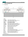
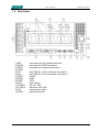

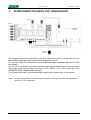
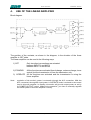


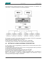


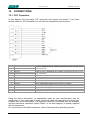
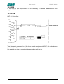
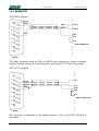


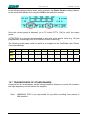


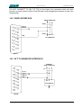


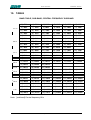


![TR4W User Manual [English Version]](http://vs1.manualzilla.com/store/data/005798737_1-5ae60a1fb1429eafa2ca68266ac47e3b-150x150.png)