1
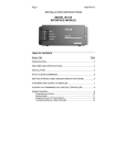
User Manual
User Manual Version 2.0
Revision Date: 2/28/2008
Copyright2008 Key Eleven, LLC
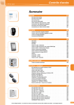
Table of Contents
Product Information............................................................................................... 3
WebIO Introduction ............................................................................................... 4
WebIO Networking ...................................................................................................................... 5
X10 Modules ............................................................................................................................... 5
WebIO Example Setup ................................................................................................................ 5
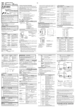
WebIO Hardware Setup ........................................................................................ 6
Ethernet Connection.................................................................................................................... 6
X10 Interface ............................................................................................................................... 6
Program Switch ........................................................................................................................... 7
1. Restoring Factory Default Settings .................................................................................... 7
2. Allowing Storage of User Configuration ............................................................................. 7
3. Display the Current IP Address ......................................................................................... 8
WebIO Network Setup .......................................................................................... 9
Setting a WebIO IP Address Using a DHCP Server ................................................................... 9
Getting an IP Address from a DHCP server ........................................................................... 9
Setting the WebIO IP Address Using the WebIO Setup Software ............................................ 10
Manually Setting the WebIO IP Address Using ARP and Ping ................................................. 11
Setting a Static IP Address (When no DHCP Server is Available) ....................................... 11
Routable Network Setup ..................................................................................... 12
Using WebIO ...................................................................................................... 15
WebIO Functions ....................................................................................................................... 15
Controlling X10 Labeled Devices .............................................................................................. 16
Send X10 Commands ............................................................................................................... 18
Toggle Commands................................................................................................................ 19
Timer ..................................................................................................................................... 20
Passcode .............................................................................................................................. 21
Setting IP Address..................................................................................................................... 24
Setting a User Passcode ........................................................................................................... 26
WebIO Security ..................................................................................................................... 27
Edit Device Labels..................................................................................................................... 28
Temperature Sensor ................................................................................................................. 30
Appendix A ......................................................................................................... 32
WebIO Detailed Manual Network Setup ................................................................................... 32
LAN setup with DHCP:.......................................................................................................... 32
LAN Setup without DHCP: .................................................................................................... 33
Appendix B ......................................................................................................... 34
Limited Warranty ....................................................................................................................... 34
Appendix C ......................................................................................................... 35
Technical Specification.............................................................................................................. 35
Product Information............................................................................................. 37
2
Product Information
For customers in the United States and Canada
This equipment had been tested and fount to comply with the limits for a Class B
digital device, pursuant to Part 15 of the FCC Rules.
These limits are designed to provide reasonable protection against harmful
interference in a residential installation. This equipment generates, uses and can
radiate radio frequency energy and, if not installed and used in accordance with
the instructions, may cause harmful interference to radio communications.
However, there is no guarantee that interference will not occur in a particular
installation. If this equipment does cause harmful interference to radio or
television reception, which can be determined by turning the equipment off and
on, the user is encouraged to try to correct the interference by one or more of the
following measures:
o Reorient or relocate the receiving antenna.
o Increase the separation between the equipment and receiver.
o Connect the equipment in to an outlet on a circuit different from that to
which the receiver is connected.
o Consult the dealer or an experienced radio/TV technician for help.
You are cautioned that any changes or modifications not expressly approved in
this manual could void your authority to operate this equipment
This device complies with Part 15 of the FCC Rules. Operation is subject to the
following two conditions: (1) This device may not cause harmful interference, and
(2) this device must accept any interference received, including interference that
may cause undesired operation.
Owner’s Record
The model number, serial number and MAC address is located on the bottom of
the device. Record the model number, serial number and MAC address in the
space provided below. These numbers are important for user use and
configuration of the Product. Refer to these numbers whenever you call upon
Key Eleven or authorizes service center regarding this product.
Model No. AFX1110
Serial No. ____________
MAC Address ________________
3
WebIO Introduction
WebIO is an Internet to power line control (PLC) network server and gateway,
providing both local Ethernet and remote Internet control of lamps, appliances
and other electrical devices in the home or office. Utilizing X10 PLC technology,
WebIO sends signals down existing power lines to control X10 compatible PLC
devices. By containing a built-in web server, WebIO allows remote users with
Internet access to connect to a WebIO via web browser, giving the remote user
control of installed X10 devices.
WebIO is built on the idea that an expensive and complex personal computer is
not needed to provide Internet access to an X10 power line control network.
Instead, WebIO is a low cost, small self-contained device that provides all the
functionality of an Ethernet to X10 gateway that is as easy to install as a home
Internet router.
WebIO communicates with X10 modules that support “On”, “Off”, “Query” and
other X10 functions. This includes appliance modules, lamp modules, AC
receptacles, light switches, dry contact modules, relays and many others readily
available devices from suppliers of X10 PLC devices.
WebIO TCP/IP Networking
WebIO provides an RJ45 interface for an Ethernet connection to a local area
network. An IP address may be assigned to a WebIO from a DHCP server or a
static IP address can be set using the WebIO Setup utility software.
For remote monitoring and control, WebIO requires a routable Internet
connection, allowing a user to connect to a WebIO from anywhere in the world
via the Internet.
WebIO network access security is provided via user assignable passcode.
WebIO configuration settings are protected from unauthorized web access via
“program mode” switch located on the WebIO back connection panel. Additional
security requires user supplied VPN device or other network security systems.
4
WebIO Networking
WebIO provides an RJ45 interface for an Ethernet connection to a LAN. An IP
address may be assigned from a DHCP server or a static IP can be set using the
WebIO Setup utility software.
For remote monitoring and control, WebIO requires a routable Internet
connection. This allows a user to connect to a WebIO from anywhere in the
world via the Internet.
X10 Modules
X10 modules plug into AC receptacles providing power to the module and
controlled devices.
The AC power line provides the path for modules to send and receive control
messages. Each X10 module on the AC power line network is addressed with a
House code and Unit code combination. There are 16 House codes assigned a
letter in the range of A-P. Unit codes are assigned numbers 1-16. X10 modules
support different Function codes, such as On, Off, Dim, and State Query.
WebIO Example Setup
The diagram below displays an example setup and operation of the WebIO:
5
WebIO Hardware Setup
Rear View of WebIO
Ethernet Connection
WebIO provides an RJ45 jack for Ethernet connection to your Local Area
Network. The left LED of the RJ45 jack will light when the WebIO is correctly
connected to an Ethernet LAN.
X10 Interface
WebIO provides an RJ12 6pin modular interface for connection to an X10
transceiver. When used with a Smart Home PowerLinc II™ X10 transceiver,
power for WebIO is provided by the PowerLinc II.
When used with the PSC05/TW523 X10 transceivers, which do not supply
power, the WebIO barrel connector is used with a 9-12volt dc (center pin
positive) power adapter. Also, an internal WebIO jumper (J6) must be moved
from the left to the right position (nearest barrel connector) to enable the barrel
connector for power. This also disables the RJ12 connector (X10 transceiver
connector) as the power source.
WebIO supports multiple X10 power line transceivers:
• The Smart Home PowerLinc II™ serial interface X10 transceiver (with
RJ12 6pin modular connector) in TW523 mode. With this transceiver the
WebIO also receives power, so no extra power supply is needed.
• The X10 Pro PSC05 (TW523) transceiver. An additional 9-12 Volt DC,
center pin positive, power supply is required to power the WebIO. Along
with a jumper changed within WebIO.
6
•
•
The PL513/PCS04 transmitter. With the PL513, WebIO can transmit X10
signals but not receive message replies from 2-way X10 modules. In
addition a separate power supply is required for WebIO.
The XM10 transceiver for 230VAC power in UK countries. In addition a
separate power supply is required for WebIO.
Program Switch
The Program Switch is located on the rear of a WebIO. This switch is used as a
security device to prevent unauthorized remote users from configuring the
WebIO. To prevent unauthorized or accidental configuration, it is important to
leave this switch in the Lock position.
The Program Switch performs the following functions:
1. Restore factory default settings.
2. Allow storage of user configuration.
3. Display current IP address
1. Restoring Factory Default Settings
To restore WebIO to factory default settings perform the following tasks:
a. Remove power.
b. Switch the Program Switch to the Program (Prg) position (away from
power barrel connector)
c. Reapply power. The WebIO boot process will display the message
"Factory Default".
d. Set the switch back to the Lock position.
Restoring to factory defaults performs three tasks:
1. Removes the user set static IP address. The factory default is to
accept an IP address from a DHCP server.
2. Clears user-set passcode, disabling the use of a passcode until a new
passcode is entered.
3. Clears all user defined X10 device labels.
2. Allowing Storage of User Configuration
Setting the Program Switch to the Prg position while the WebIO is powered
allows the user to perform three tasks:
1. Program a static IP address
2. Set a passcode as described later in this manual.
3. Define labels/names for X10 devices
WebIO will save these setting to non-volatile memory for recall even if power
is lost and restored.
The function of the Program Switch is also used for security. Remember to
set the Program Switch to the normal (Off/Lock) position after programming
to prevent unauthorized remote users from configuring WebIO.
7
3. Display the Current IP Address
The program switch is also used to display the current IP address of the
WebIO. Switching to any position will update the display with the WebIO
current IP address. This becomes useful during installation when a DHCP
server is used.
IMPORTANT:
The function of the Program Switch is also used for security.
Remember to set the Program Switch to the normal (Off/Lock)
position after setup programming to prevent unauthorized
remote users from configuring your WebIO.
The Lock position also prevents an accidental Restore to
Factory Defaults on unintentional power cycle of WebIO.
8
WebIO Network Setup
WebIO can operate with either an IP address obtained from a DHCP server, by
using the WebIO Setup utility software, or by using a computers operating
system’s ARP and Ping tools.
Setting a WebIO IP Address Using a DHCP Server
Getting an IP Address from a DHCP server
WebIO will accept an IP from a DHCP server.
Switch the WebIO program switch to display its current IP address on the
LCD.
If the WebIO shows an IP address of 0.0.0.0 then an IP address has not
been received. It can take many seconds to receive an IP from a DHCP
server.
When using DHCP with WebIO, Internet routing to the WebIO may not be
practical in the case where WebIO is power cycled (rebooted) and then
receives a different IP address then previously assigned. Also Routers may
not have the ability to forward to an IP address in the range of the DHCP
assigned address. To avoid this problem when using a router with DHCP
enabled it is best to us a static DHCP service (or Bootp service) where the
DHCP server assigns a defined IP address to the WebIO based on the
WebIO MAC address.
Note: In some rare cases depending on DHCP server used, WebIO may
prioritize DHCP over static, regardless of the WebIO Lock switch position.
Such that if you assign WebIO a static IP address on a network with a DHCP
server, WebIO may accept a new IP address received from the DHCP
server. In some rare cases, in using the WebIO static IP function, you may
need to not have a DHCP server (not so practical) or have the DHCP server
always assign the same IP dependent on MAC address. (Static
DHCP/bootp).
9
Setting the WebIO IP Address Using the WebIO Setup Software
The WebIO CD-ROM includes an installation program for the WebIO Setup utility
software. The installation program and the WebIO Setup utility will work with
Windows 9x, 2000, XP, and Vista. The WebIO Setup utility provides for an easy
IP address configuration tool.
For installation of the WebIO Setup utility, run “setup.exe” from the WebIO Setup
CD-ROM. After installation run the WebIO Setup utility from your Windows
Program menu.
The WebIO Setup utility contains the following form:
1. In the MAC Address field, enter your unique MAC address found on the
bottom of the WebIO.
2. In the WebIO IP Address field enter the desired IP address to be
assigned to the WebIO.
3. Click the Set IP Address button. After a few moments a message will
notify success or failure.
On success, WebIO Version field will display the WebIO firmware version.
Note: This Application uses ARP and Ping behind the scenes as described in
Appendix A.
For more information on WebIO Setup software, see manual WebIO Setup.
To instruct WebIO to store its IP address in Flash memory, see the section
“Using WebIO – Setting an IP address”.
10
Manually Setting the WebIO IP Address Using ARP and Ping
Setting a Static IP Address (When no DHCP Server is Available)
ARP and Ping can be used to set the WebIO IP address. There must not be
a DHCP or BOOTP server on the same network as WebIO when using this
method for setting the IP address.
Windows 9x example:
IP for WebIO: 192.168.1.25
MAC for WebIO: 00-03-75-1f-0c-9f
PC’s IP address: 192.168.1.150
1. Enter the desired IP address for the MAC address of the WebIO into
your PCs ARP table. From a Windows command prompt Enter:
arp –s 192.168.1.25 00-03-75-1f-0c-9f 192.168.1.150
2. Ping the IP address of the WebIO by entering the following command
at a Windows command prompt.
ping 192.168.1.25.
When received, the WebIO will accept this address.
To instruct WebIO to store its IP address in Flash memory, see the section
“Using WebIO – Setting an IP address”.
For more information on setting an IP address see Appendix A.
11
Routable Network Setup
To setup WebIO for remote Internet access, WebIO will need to be assigned
either an Internet IP address, or more commonly, placed behind a router (LAN
side) that has an Internet IP address and is configured to forward via IP port
forwarding to the IP address of the WebIO. This method is referred as “router
port forwarding” and “Network Address Translation” (NAT)
Router Setup (router port forwarding)
Most routers have a feature that allows a user-configuration for port forwarding.
Port forwarding is used to allow an outside request from the Wide Area Network
(WAN) side of the router to be routed to a specific IP address of a device or
computer existing on the inside router network, referred to as the Local Area
Network (LAN).
Message requests sent over a TCP/IP network (such as the Internet) use port
numbers as a way to specify a specific service on a server. For example, a Web
service will listen on port 80 where as an email service on the same server will
listen on port 25. This way a message directed to the server using an IP address
will specify a port number to direct the message to the appropriate service (web
service or e-mail service). As another example, when a web browser asks a web
server for a web page, the browser sends a message to the server, referring to
its IP address and referring to the web services port number on the server. By
default a web browser sends requests to port 80, the default port used by web
servers.
When setting up a router to forward a port to the WebIO, using the default of port
80 is suggested. However the WebIO will accept an HTTP connection on any
port, allowing for router setup in the case that an existing web server on the LAN
side of the router is already assigned to port 80. The WebIO would then need to
be assigned to a different port such as 81 or 8080.
When using a port other than 80, you will need to specify the port number on the
browsers URL using “:” {and port number}. For example to specify port 8081 at
IP address 24.119.179.20, enter: http://24.119.179.20:8081. Or when using a
domain name, enter: http://www.keyeleven.com:8081
12
Below is a network topology diagram that outlines router port forwarding:
13
Above is a screenshot of a NetGear router Port Forwarding configuration. Note
entry #3 for WebIO on Port 8087 forward to LAN IP address 192.168.1.77.
14
Using WebIO
WebIO Functions
WebIO includes an embedded web server, for providing a simple interface to the
user via web browser. This allows for simple operation with no additional
software required to be installed on the user’s PC. The simple web pages of
WebIO even allow for operation from a mobile Smartphone or similar devices
that provide a web browser.
When using a Smartphone with a web browser it become advantageous that
WebIO uses HTML frames allowing the small phone screen size to focus on a
single frame rather than the full web page.
The WebIO web interface provides for:
• Controlling X10 devices by label/name
• Sending specific X10 commands
• Query of an X10 device state
• Setting an LCD message
• Setting a Static IP address
• Setting a User Passcode
• Editing X10 device labels
• Reading WebIO temperature
The following sections describe the functions of WebIO.
15
Controlling X10 Labeled Devices
The WebIO web interface provides two methods for controlling X10 Devices.
The Control X10 Labeled Devices page (shown below) allows for easy control
of X10 On/Off commands for predefined X10 devices.
The Control X10 Labeled Devices page (above) shows a table of predefined
X10 Devices. The On and Off columns contain links for setting the On/Off state
of the device in the selected table row.
When a WebIO passcode is set/enabled, the On/Off links will not trigger X10
commands until the correct passcode is entered in to the Enter Passcode field
and the Unlock button is clicked. After the passcode has been submitted the
Clear passcode when finished link must be selected to re-lock the WebIO from
X10 operations.
16
The Set dim level of last device set on up and down arrow buttons are used to
adjust the dim level of a lamp module that supports X10 dim commands. Only the
last lamp module set on or off will be affected by the dim commands.
The Control X10 Labeled Devices web page interface is designed for
convenience to the user for operating several X10 commands with ease. This is
accomplished by using X10 labels, on/off links and a single passcode unlock
process.
It is important for the user to understand that the unlock process sets WebIO into
an unlocked state allowing anyone access to sending X10 commands. This is
due to WebIO not having a capability of tracking secure HTTPS sessions with
users as is common with full featured Internet web servers. So it becomes
important to clear the passcode when finished with using the Control X10
Labeled Devices interface to re-lock WebIO from X10 command use.
Also, WebIO will enter locked mode whenever an incorrect passcode is entered
and a passcode is set/enabled.
Also note that The Send X10 Commands web page interface does not set
WebIO into an unlocked state but instead requires the correct passcode to be
entered with every X10 command function when passcode is set/enabled.
IMPORTANT:
When using the Control X10 Labeled Devices interface and a WebIO
passcode is set/enabled. The Clear passcode when finished link must
be selected to re-lock WebIO from unauthorized use of X10 command
functions.
17
Send X10 Commands
Another method for controlling X10 devices is to use the Send X10 Codes web
page. This page allows for manually selecting X10 device House code, Unit
code, and the Command to be sent. In addition a timer can be set for when the
operation should occur.
To execute an X10 function, select House code, Unit code and Command from
the drop list boxes then set an optional timer and enter Passcode (if enabled)
and click the Execute button.
A table of labeled X10 devices is provided for convenience along with timer
status.
18
WebIO includes support for most of the X10 protocol commands.
WebIO supports sending the following X10 commands
• On – Used to turn on a device
• Off – Used to turn off a device
• Dim – Used to Dim a lamp module
• Bright – Used to Brighten a lamp module
• All Units Off – Used to turn all modules off of same House
Code
• All Lights On – Used to turn all lights on of same House
Code
• All Lights Off – Used to turn all lights off of same House
Code
• Status Request (Query 2-way device), including receiving
On/Off messages
The following X10 commands are not supported by WebIO.
WebIO does not support the following X10 commands:
• Pre-Set Dim High
• Pre-Set Dime Low
• Extended Data
WebIO adds additional non-X10-protocol commands.
WebIO adds the fallowing X10 functions
• On-Wait-Off – Where wait is 4 seconds
• Off-Wait-On – Where wait is 4 seconds
Toggle Commands
The WebIO Toggle action is: (on-wait-off) or (off-wait-on) with a 4 second wait
state.
This feature is particularly useful for remotely rebooting Network Routers and
other equipment where remote or local access to WebIO will be briefly
interrupted.
For Example; In case of remotely rebooting a TCP/IP Network Router of which
WebIO is connected, and the Router is connected to an X10 Appliance module:
A WebIO toggle “off/on” command sent to the Routers X10 module, will power off
the router, causing WebIO to be inaccessible via TCP/IP network. Then to
complete the toggle command, WebIO waits 4 seconds and sends an “on”
19
command providing power back to the Router and access to WebIO after the
Router has booted and become operational again.
The Toggle feature is new to WebIO version 1.0.30. WebIO version is displayed
on the LCD as it is powered up.
Note: X10 is not necessarily practical for controlling and maintaining a secure
and reliable environment for network equipment.
Timer
The WebIO X10 command timer is new to version 2.0. This feature allows a
command to be executed at a later time.
Time is configurable in minutes from 1-254. A value of 0 is used to execute a
command immediately. A value of 255 is used to cancel/clear an existing timer
configuration. When using timer value of 255 to clear the timer, the House, Unit
and Command values in the drop down boxes have no effect.
Only one timer exists such that only one X10 command can be configured to be
sent on the configured time.
When a timer is set, WebIO can still be used to execute other X10 commands
with a timer value of 0. If a timer value other then 0 is used, the current timer
configuration will be replaced by the new configuration.
The timer’s time is only accurate to better then +/-2% of set time, such that a
timer set for 60 minutes may occur up to 1 minute and 12 seconds early or late.
Time is effected by WebIO temperature and time can be delayed slightly when
used to execute other X10 commands or functions.
When a timer is set, its status can be viewed at the bottom of the Send X10
Codes page. To get an updated minutes remaining status, a page refresh is
required. A message of Not Set is displayed if the timer in not currently set or
has completed.
The timer status is reported as H:{House code} U:{Unit code} C:{Command}
T:{minutes remaining}.
Note: It is not recommended to use the timer function for critical applications, as
X10 is not guaranteed to be reliable such that a person is not in a position to
supervise the X10 action. Also the timer configuration can be lost due to WebIO
losing and regaining power (power cycle). WebIO does not store the timer
configuration in non-volatile memory as WebIO does not have a date-time clock
to know the amount of time passed on power outage. Also WebIO has a
watchdog feature that can cause auto reboot if a problem occurs, though this
should be a very rare event.
20
Passcode
When a WebIO passcode is set/enabled, the passcode must be entered into the
Enter Passcode field before clicking the Execute button. If no passcode or the
incorrect passcode is entered, the WebIO will not execute the selected X10
function. Unlike the Control X10 Labeled Devices page, the passcode must be
entered for each command sent.
When no passcode is set/enabled, then this field can be left blank.
WebIO does not report when the incorrect passcode has been entered. This
provides additional security, not allowing an unauthorized user to “discover” the
correct passcode using trial and error.
Also note that The Send X10 Commands web page interface does not set
WebIO into an unlocked state but instead requires the correct passcode to be
entered with every X10 command function when passcode is set/enabled.
21
Get X10 Device State
This feature provides for “asking” an X10 device for its state being “on” or “off” by
using the X10 Status Request command. This feature is useful for validating
that a device is in the expected state after sending an X10 command.
Get X10 device state feature is only supported by X10 devices that can reply to
the Status Request command (often referred to as 2-way X10 devices). This
feature also requires that WebIO be used with a “2-way” X10 Transceiver such
as the Powerlinc or PSC05/TW523.
Note: Some X10 2-way devices seem to be more reliable at receiving
commands then they are at replying to status requests.
WebIO will report a reply from a status request/query as either on or off. If no
status reply is received within 4 seconds. WebIO will report with a No Response
message.
Above is the Get X10 Device State interface
22
Set LCD Message
The Set LCD Message page provides an interface for displaying messages on
the WebIO LCD display. The LCD will display 2 lines of 16 characters.
To display a message, enter the message into the Line 1 and Line 2 text boxes,
then press the Execute button.
23
Setting IP Address
The WebIO, Change IP Address page provides an interface for saving an IP
address to the WebIO non-volatile memory.
WebIO can be configured to remember a static IP address, even when power is
cycled. This is useful when a DHCP server is not available to assign the WebIO
a dynamic IP address or specific static IP address, or you do not want to
manually assign an address each time the WebIO is power cycled. Another use
for assigning a static IP address is when a router or other software process
needs to know the WebIO assigned IP address for routing messages or
connecting to it.
To save an IP address:
1. Move the WebIO Program Switch to the program position.
2. From a browser go to the WebIO Change IP Address page, enter the IP
and submit the page. Note the LCD message displaying the new static IP.
3. Switch the Program Switch back to the Off position to prevent remote
programming and prevent the restoration to factory defaults on reboot.
Note: If you used ARP to set an IP address for the WebIO, the WebIO IP Admin
page may only accept the same IP as in your PC’s ARP table. To assign a
different IP address to WebIO, first clear your ARP table using arp –a. Then
display your ARP table use arp –d {IP address to delete}, to remove an IP
24
address before using the above procedure to save a different IP address in
WebIO.
25
Setting a User Passcode
A WebIO can be configured with a passcode for preventing unauthorized control
of X10 devices. When a passcode is set both the Control X10 Labeled Devices
and the Send X10 Code web pages will require the passcode field to contain
the correct passcode to send an X10 command. When the passcode is incorrect
WebIO gives no indication of invalid passcode and no indication that it did not
perform the X10 command. This provides additional security, not allowing an
unauthorized user to “discover” the correct passcode using trial and error. To
verify a device state, use the Get X10 Device State web page for supported X10
2-way devices.
The WebIO, Passcode Admin page provides an interface for saving a passcode
to the WebIO non-volatile memory.
Setting a WebIO Passcode:
1. Move the WebIO Program Switch to the program position (toward the
X10 transceiver connection)
2. From a browser go to the WebIO Passcode Admin page, enter a 4
character alphanumeric (case sensitive) (plus ASCII non-white-space
symbols) passcode and submit the page. Note the LCD message
displaying acceptance or failure of the new passcode.
WebIO will only use the first four characters when a passcode of more
than 4 characters are entered.
3. Switch the Program Switch back to the Off position to prevent remote
programming and prevent the restoration to factory defaults on reboot.
When a passcode is set, WebIO will display the passcode on the LCD for 2
seconds on its boot process (when power is applied).
Note that a combination of 4 alphanumeric characters plus symbols provides for
over 71 million combinations.
To remove a passcode WebIO must be restored to factory defaults. See the
section titled “Restoring Factory Default Settings”
26
Above: WebIO interface for setting a passcode
WebIO Security
The WebIO passcode provides a minimum amount of security. All WebIO
information including the passcode sent from a users web browser to the WebIO
web server is not encrypted, this means that it is possible for someone with the
right tools and knowledge could discover your passcode. For this reason it is not
suggested that a WebIO open to the Internet (Internet routable) be used for
critical applications such as controlling a thermostat.
Even though WebIO doesn’t provide high Internet security, there are methods for
adding high security that are beyond the scope of this manual.
Two examples of a secure WebIO setup:
1. A Virtual Private Network (VPN) can be setup that provides an encrypted
tunnel over the Internet between a remote user’s computer or LAN and a
local router of which the WebIO is hiding behind.
2. WebIO can be hidden behind a secure web server, which relays remote
messages to the WebIO.
27
Edit Device Labels
WebIO provides for the naming of X10 devices. Rather than memorizing devices
by X10 Address, a friendly name can be assigned to a House Code and Unit
Code and its associated On and Off functions. Eight X10 devices can be named
on the WebIO web interface.
The WebIO, Edit Labels web page interface provides for assigning names to
X10 address to be saved to the WebIO non-volatile memory. Just as with the IP
address and Passcode, X10 labels are protected using the WebIO program
switch.
Assigning Device Labels:
1. Move the WebIO Program Switch to the program position (toward the
X10 transceiver connection)
2. From a browser go to the WebIO Edit Labels page, for each label,
enter Label name and its associated House Code and Unit Code.
This same interface can also be used to edit existing labels.
3. When completed, click-select the Submit button
4. Verify Labels by navigating to the Control X10 Labeled Devices
page.
5. When satisfied, switch the Program Switch back to the Off position to
prevent remote programming and prevent the restoration to factory
defaults on reboot.
When WebIO is restored to factory defaults, all labels are returned to bank with
default House and Unit Codes. See the section titled “Restoring Factory
Default Settings”
WebIO device labels can also be configured using the WebIO Setup utility
software. See WebIO Setup software manual.
28
Shown above is the Edit Labels web page interface.
Edit Labels as a web page interface is new to WebIO version 2.0 (as displayed
on the WebIO LCD during power up).
29
Temperature Sensor
WebIO includes an internal temperature sensor and web page interface for
reading the temperature in degrees Celsius and Fahrenheit. This sensor
provides an approximate evaluation of the room ambient temperature of which
WebIO is installed. But due to the sensor being internal to WebIO, temperature
readings maybe slightly higher or lower then ambient temperature by up to 2
degrees Celsius or more.
The WebIO Temperature interface displays both Degrees Celsius and
Fahrenheit. Select the “Refresh Temperature” button to capture a new
temperature reading.
Temperature sensor range is from -20C to 50C. (Although WebIO operating
temperature range is 0C to 50C). Temperature accuracy is typically better then
+/- 5 degrees Celsius. Resolution is displayed in 0.1 degree increments
Note: When WebIO is powered up, allow 5 to 10 minutes for the temperature
reading to stabilize. This is due to the sensor being internal to the WebIO
enclosure and the temperature reading being compensated for internally
generated heat by the WebIO electronics. Once WebIO has “warmed up”
Temperature reading will fairly accurately represent ambient room temperature.
30
Temperature is new to WebIO version 1.3 (as displayed on the WebIO LCD
during power up).
31
Appendix A
WebIO Detailed Manual Network Setup
LAN setup with DHCP:
1. Connect WebIO to a 10/100BT hub or switch. The left green LED of the
WebIO RJ45 jack will light when correctly connected.
2. After about 5 seconds the WebIO will indicate its IP address. An IP
address of 0.0.0.0 indicates the WebIO had not yet received and IP
address for the DHCP server. It can take a minute or more for the WebIO
to receive and IP address.
3. Change the position of the Program Switch to update the display with the
current IP address. After receiving an IP address, the program switch
should be set in the normal (off) position to prevent reset to factory default
if rebooted and to lock out unauthorized remote programming.
4. Connect to the WebIO using a web browser. Connect to the URL of the
WebIO by manually typing its IP address: http://{IP address}
For example: http://192.168.1.100
5. A successful connection will display the main WebIO page.
6. At this time you may choose to set a Static IP (see instructions: Setting
Static IP Address). Without a Static IP, upon reboot of the WebIO it may
receive a different DHCP assigned IP address.
Note: In some rare cases depending on DHCP server used, WebIO may
prioritize DHCP over static, regardless of the WebIO Lock switch position.
Such that if you assign WebIO a static IP address on a network with a DHCP
server, WebIO may accept a new IP address received from the DHCP
server. In some rare cases, in using the WebIO static IP function, you may
need to not have a DHCP server (not so practical) or have the DHCP server
always assign the same IP dependent on MAC address. (Static
DHCP/bootp).
32
LAN Setup without DHCP:
1. This setup requires the use of ARP and Ping. A DHCP or BOOTP server
must not be present as these will interfere with an ARP command. If
either a DHCP or BOOTP server exists, connect the WebIO using a
crossover cable to a PC.
2. Connect WebIO to a 10/100BT hub or switch. The left green LED of the
WebIO RJ45 jack will light when correctly connected.
3. Use ARP and Ping to assign an IP address to the WebIO. From a PC
running Windows, open a command window.
a. Obtain your IP address:
i. Under Window9x, Enter: ipconfig
ii. Linux, Enter: ifconfig
b. Enter the IP address and MAC address of the WebIO into your
ARP table: arp –s {WebIO IP address} {WebIO MAC address}
{your PC IP address}.
i. Windows 9x Example:
arp –s 192.168.1.101 00-aa-00-62-c6-01 192.168.1.10
ii. Linux Example:
arp –s 192.168.1.101 00:aa:00:62:c6:01 192.168.1.10
c. Assign the IP address to the WebIO, Enter: ping {WebIO IP
address},
i. Example: ping 192.168.1.100
d. If the ping receives a reply, then the WebIO has received the IP
address. If no reply is received, see Troubleshooting - Assigning IP
address using ARP and Ping.
4. Verify that the WebIO has received the IP Address (ensure the reply is not
from another device). Change the position of the Program Switch to
update the display with the current IP address. The Assigned IP address
should be displayed.
5. Connect to the WebIO using a web browser. Connect to URL: http://{IP
address} for example: http://192.168.1.100
6. A successful connection will display the main WebIO page.
7. At this time you should assign a Static IP address (see instructions:
Setting Static IP Address). Without a Static IP, upon reboot of the WebIO
it will look for a DHCP server or default to IP 0.0.0.0.
8. If using a crossover cable, the WebIO can now be plugged into the LAN
with no need to power down.
33
Appendix B
Limited Warranty
Key Eleven, LLC. Warrants this Product (not including any accessories) against defects in
material or workmanship as follows:
Labor and Parts: For a period of 60 day from the date of purchase, if this Product is determined to
be defective, Key Eleven will repair or replace the Product, at its option, at no charge, or pay the
labor charges to any Key Eleven authorized service facility. After the Warranty Period, you must
pay for all labor charges.
To obtain warranty service, you must take the Product, or deliver the Product freight prepaid, in
either its original packaging or packaging affording an equal degree of protection, to Key Eleven
at your expense.
This warranty does not cover customer instruction, installation, set up adjustments or signal
reception problems.
This warranty does not cover cosmetic damage or damage due to acts or God, accident, misuse,
abuse, negligence, commercial use, or modification of, or to any part of the Product. This
warranty does not cover damage due to improper operation or maintenance, connection to
improper voltage supply, or attempted repair by anyone other than a facility authorized by Key
Eleven to service the Product. This warranty does not cover Products sold AS IS or WITH ALL
FAULTS, or consumables (such as fuses or batteries). This warranty is valid only in the United
States.
Proof of purchase in the form of a bill or sale or receipted invoice which is evidence that the unit is
within the Warranty period must be presented to obtain warranty service.
Repair or replacement as provided under this warranty is the exclusive remedy of the consumer.
Key Eleven shall not be liable for any incidental or consequential damages for breach of any
express or implied warranty on this product. Except to the extent prohibited by applicable law, any
implied warranty of merchantability or fitness for a particular purpose on this product is limited in
duration to the duration of this warranty.
In no event shall Key Eleven be liable for special, incidental, consequential or other damages
resulting from the possession or use of this product, including without limitation damage to
property and, to the extent permitted by law, personal injury, even if Key Eleven knew or should
have known of the possibility of such damages.
Some states do not allow the exclusion of limitation of incidental or consequential damages, or
allow limitations on how long an implied warranty lasts, so the above limitations or exclusions
may not apply to you. In addition, if you enter into a service contract with Key Eleven within 60
days of the date of sale, the limitation on how long an implied warranty lasts does not apply to
you. This warranty gives you specific legal rights, and you may have other rights which vary from
state to state.
34
Appendix C
Technical Specification
Technical Features
• Built in web interface for X10 power line control and WebIO configuration
• LCD display for indication of IP address, configuration messages and user
messages
• DHCP client for easy Ethernet network installation - Static IP address
settings when DHCP is not available
• Supports X10 power line “on”, “off” and “query” commands
• Supports popular X10 power line transceivers (Powerlinc and TW523)
• No computer required, WebIO is a total power line control system and web
server in a box
• Very low cost embedded systems design based on two 8-bit
microcontrollers
• No operating system, true micro code for reliable functionality and rapid
boot process
• WebIO configuration is secured via a physical “program mode” switch to
prevent unauthorized configuration via web interface
• Hardware watchdog for insured uptime
Specifications
Model Number
AFX1110
Ports
1 RJ45 10 Megabit Ethernet
1 serial ports for PLC transceiver
Storage
EEPROM for configuration storage of IP address and security key
Expansion ports
Internal GPIO lines
Indicators
LCD interface for power, IP address,
Communication activity and Gateway status
LED Ethernet status indicators
Power Line Controller
Supports the SmartHome X10 PowerLinc
Also supports the X10 TW523 (requires 9-12VDC power, center tap
positive (+) at the 2mm barrel connector)
Environmental
Dimensions
1-7/16" x5-1/4" x3" (HxWxD)
Unit Weight
6.0 oz.
Enclosure
Plastic enclosure with mounting holes
Power
Input 9-12VDC
Power consumption 64mA at 12VDC
Sleep mode as low as 34mA, 12VDC
35
Power Supply
(included)
Input: AC120V~
Output: DC12V 250mA
Certifications
WebIO is in compliance with the electromagnetic compatibility
requirements defined in FCC Part 15 Subpart B.
And Canada ICES-003, Issue 4:2004 Class B.
Operating Temp.
0° to +50°C, (limitations due to LCD display)
Storage Temp.
-10° to +60°C, (limitations due to LCD display)
RoHS
Not RoHS compliant
36
Product Information
For more information and software updates, visit the WebIO web site:
http://www.webio.us
http://www.keyeleven.com
or contact:
Key Eleven
1322 11th Street South
Moorhead, MN 56560 USA
Copyright2008 Key Eleven, LLC
Windows is a registered trademark of Microsoft Corporation
37