1
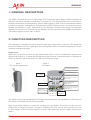
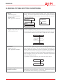
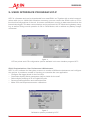
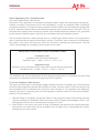
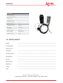
MANUAL
HANDHELD INSTRUMENT FOR CO2 MEASUREMENT
made to measure
SD021
MANUAL
CONTENT
HANDHELD INSTRUMENT FOR CO2 MEASUREMENT ..............................1
CONTENT ................................................................................................3
1. GENERAL DESCRIPTION .....................................................................4
2. FUNCTION DESCRIPTION....................................................................4
3. DEFAULT PUSH BUTTON FUNCTIONS .................................................5
4. INSTANTANEOUS CO 2 CONCENTRATION ............................................6
5. TEMPERATURE ....................................................................................6
6. CHARGING OF BATTERY .....................................................................6
7. SELF DIAGNOSTICS AND CALIBRATION .............................................7
8. LOGGING CO 2 AND TEMPERATURE .....................................................7
9. USER INTERFACE PROGRAM UIP-P ....................................................8
10. FILE HANDLING & APPLICATION FILES ........................................... 10
11. TECHNICAL SPECIFICATIONS ......................................................... 12
12. DATA SD021 .................................................................................... 13
3
MANUAL
1. GENERAL DESCRIPTION
The SD021 portable sensor is a light-weight CO2 instrument with a digital display designed to
measure the carbon dioxide concentration in ambient air. The display shows the current carbon
dioxide concentration and temperature. Built-in data logging for both CO2 and temperature makes
it perfect for worksite investigations. The gold-plated carbon dioxide sensor measures the carbon
dioxide concentration in ppm. State-of-the-art non-dispersive infrared technology and automatic
calibration functions have resulted in great reliability, accuracy and long-term stability of operation.
The battery capacity is more than 12 hours.
2. FUNCTION DESCRIPTION
The instrument is durable but can be extra secured by a safety strap on the top. The measuring
sensor is inside the unit. Two openings in the housing make the air circulate through the unit. These
openings must be kept open!
Please note!
Whenever you go from a cold to a warm environment there is a risk of condensation (anyone with
glasses has noticed it). To avoid that this influences the accuracy of the instrument it is important to
allow it to adjust to the environment for a few minutes before usage.
figure 1
The flow throught the unit
figure 2
Front panel
On/Off and Function button
CO2 concentration in ppm
status indicator
Temperature (in Celsius - can
be reconfigured from PC to
Fahrenheit)
Red Led: High Alarm
5000 ppm CO2
battery indicator
1st Green Led
Always activated in
On or Sleep Mode
2nd Yellow Led: Low Alarm
2000 ppm CO2
2nd Green Led
600 ppm CO2
1st Yellow Led
1000 ppm CO2
The display shows the instantaneous CO2 value and temperature. The instantaneous CO2 value is
also easily overviewed with the front panel LEDs.
Note: If the status indicator is shown the readings are not reliable! The actions to take are then
always first to charge the battery, second to recalibrate the CO2 sensor zero point (put the unit
in CALb Mode). If still the status indicator is shown after these two actions, please contact your
dealer!
4
MANUAL
3. DEFAULT PUSH BUTTON FUNCTIONS
On Mode
• measuring CO2
• measuring temperature
• logger active
• ABC algorithm disabled
Push te button until the display shows “tESt:, then release the
button. The unit will perform a full self-test sequence showing
the LEDs response for the alarm set points. After the test the
unit is in On Mode.
Explanation
Off Mode
Push Button
“tESt”
Release Button
On Mode
Power Off
From On Mode, push the button until all front panel LEDs are
• logger resets and the sample turned off. While pushing the button the unit will pass through
counter will be lost
the mode CALb. If you accidentally release the button too early, just push the button one to reach On Mode and try again.
On Mode
“CALb”
Off Mode
CALb Mode
• logger on hold
• ABC algorithm enabled
From On Mode, push the button until the display shows CALb,
then release the button. This will activate the Automatic Calibration ABS that requirers 5 hours to complete one calibration
cycle. The instrument continues to execute calibrations every
four hours as long as it is left in CALb Mode. Intended for overnight charging in fresh air, with minor calibration adjustment
automatically performed.
To get back to the On Mode, just push the button once.
On Mode
“CALb”
Back light & Application
Function Execution
Can be turned on temporarily by pushing the button. The
backlight is turned off after 8-16 seconds. Application function
for standard default setting is just backlight.
5
MANUAL
4. INSTANTANEOUS CO2 CONCENTRATION
The instantaneous CO2 concentration is shown in the upper part of the display. A rough picture of
the CO2 concentration is also given by the five LEDs found below the display.
LED indicator functions (factory settings):
Green 1
always lit when the unit is on
Green 2
> 600 ppm
Yellow 1
>1000 ppm
Yellow 2
>2000 ppm
Red 2
>5000 ppm
5. TEMPERATURE
Temperature is presented in Celsius, but can be reconfigured from PC to be in Fahrenheit. To measure an accurate reading in ambient air, the unit should be hanging in the safety strap. That orientation minimizes interference from internal heat sources. The sensor may take some half an hour to
reach thermal equilibrium and accurate readings.
Note: Charging the unit will result in a temperature rise inside the unit that disturbs the temperature
measurement!
6. CHARGING OF BATTERY
Charging of the battery can be done with the unit in Off-, CALb- or On Mode. The electronic circuitry
gets activated by charging also in Off Mode, but will return to initial state when disconnected. When
the DC- adapter is connected the charging of the battery is indicated by the rolling battery icon.
When the battery is fully charged the battery icon lits continuously. The SD021 unit automatically
stops charging when the battery is fully charged.
The charging time for a completely discharged battery is 4±1 hours and the battery capacity is
more than 12 hours.
figure 3
Connections
Calibration Gas Inlet
DC-Adapter
Communication Port
6
MANUAL
7. SELF DIAGNOSTICS AND CALIBRATION
The SD021 is basically maintenance free. The system contains complete self-diagnostics, executed
automatically every time the power is turned on. The unit will then perform a full self-test sequence
showing the LEDs response for the turn-on set points. SD021 is working with continuous self-diagnostics during operation (On Mode). If any error is detected, then the Status Indicator Segment will
be lit.
The sensor has an automatic calibration function to secure long-term accuracy. It’s called Automatic
Baseline Calibration (ABC), implemented to eliminate any zero point drift of the infrared sensor. ABC
calibration cycles are performed in 4 hours intervals. During some minutes of that time fresh air
(CO2 concentration between 380-420 ppm) has to be present. ABC function is only active in “CALb
Mode” (after one hour delay) and requires 1 to 5 hours to perform one calibration adjustment.
Each such adjustment is limited to a calibration tuning of about 130 ppm CO2. Several consecutive adjustments might be performed, if required, for each additional 4 hours period stay in “CALb
Mode”.
The CALb Mode is intended for overnight charging in an area with good ventilation, or close to the
fresh air inlet.
8. LOGGING CO2 AND TEMPERATURE
SD021 continuously logs the CO2 and temperature values. To use this feature a PC and a special
serial cable is required, together with the SD021 freeware UIP_P (available at www.SD021.com).
This is useful, for example, when you are investigating ventilation systems, or doing worksite investigations, over several days. Each of the two parameters can be logged up to 896 samples in a FIFO
memory (“first in first out”). The default sampling interval is 10 minutes, which results in more than
6 days and nights of recording time.
If the unit is turned on for a longer period old data gets eventually over-written, keeping the records
of the last recorded 896 data samples. Depending on selected sample interval you can make longer
or shorter investigations over time. The logger is always active in On Mode. To reset the logger, just
switch off the unit (without any battery charger connected) and turn it on again. That will force the
sample counter to start from zero.
In CALb, the logger function is kept on hold. This is useful when you want to take a pause in measuring, for example, if you are doing a worksite investigation and have to leave the area for some
period. When the unit is switched back into On Mode it will resume the started recording period.
Switching the unit into OFF Mode, with the battery charger connected until switched back into ON
Mode again, will also pause and resume the data logging.
It’s preferred to start a logging period with a fully loaded battery and avoid charging. Charging the
battery generates extra heat inside SD021 that will interfere with the temperature measurements.
Please, remember: Putting SD021 in Off Mode without any battery charger connected will reset to
zero the sample counter from the previous logged data. The data itself remains, however, until new
recordings eventually over write it.
7
MANUAL
9. USER INTERFACE PROGRAM UIP-P
UIP-P is a freeware and can be downloaded from www.SD021.se. Together with a serial communication cable (art. no. A232-0740 offered as accessory) you can connect the SD021 unit to a PC for
functional reconfigurations of the unit, for sensor maintenance, and to do data extractions from the
internal data logger. This data communication can be performed in OFF Mode during battery charging, as well as during normal operation in ON or CALb Modes, with or without any battery charger
connected.
figure 4
LED set points and LCD configuration options available in the user interface program UIP-P
SD021 Customizations, User Preferences & Maintenance
UIP-P is a PC software tool that gives access to a number of different maintenance and configuration options. It provides a number of functions to customize the user application:
• Configure the trigger levels for the five LEDs.
• Customize display. Which parameters shall be visible for the user?
• Select display readings in SI or English/US units
• Save and load application and customized files.
• Make CO2 and temperature sensor calibrations.
figure 5
Calibration options provided by UIP-P
8
MANUAL
SD021 internal data logger
The internal data logger is active in On Mode
and resets in Off Mode (resets only if battery
charger is not connected). All samples taken
during the turn-on time (max 896 samples)
can be viewed with the User Interface Program
UIP-P.
From UIP-P it is also possible to save all data in
a PC text file for storage or further data processing, for instance, in EXCEL or any other spread
sheet software.
figure 6
Figure 6 shows an example of a 46 hours recording extracted from the SD021 unit using UIP-P. Note
the influence on temperature readings from battery charging, as the charger was connected during
the first 22 hours! This graph also shows that the unit was fully functioning without any power connected over the last 24 hours, twice the rated portable operation time!
Selecting “Update” in the UIP-P “Logger history” map will only display data up to the time position of
the sample counter. If battery-operating time exceeds, the unit will automatically switch off and the
sample counter from the previous session of recorded data resets to zero (as is the case if manually
setting SD021 in Off Mode without battery charger connected). The old data still remains, however,
until new recordings eventually overwrite it. After a power up such “lost” data may be recovered
by selecting “Update” with the right mouse button.
figure 7
“Recovery” (memory dump) of yesterday’s recording (Figure 6) by using “Update” with right mouse
click. The arrow points at a data discontinuity indicating the memory position of the sample counter
just before the power was lost.
9
MANUAL
10. FILE HANDLING & APPLICATION FILES
Together with a communication cable (accessory) and the user interface program UIP-P it is possible to select from a directory and load different application files into SD021. An application file will
customize the unit for a certain professional application. Typically, the application file adds to the
default unit some mathematic algorithm that will be executed by the push-button when the unit is in
On Mode. Also, the display options will be enhanced and include the result of this extra function.
SD021 plans to build up with time a library of different such application files. These files are free
and are included in the UIP_P software package, which can be downloaded from SD021’s web
site www.SD021.com. You are welcome to suggest new and suitable applications for this library by
contacting your distributor!
To load an application file from the library into the unit, proceed as follows:
• Connect the cable and start the UIP_P software to establish the PC connection
• You might want to save the existing unit configuration for future restoration. If so, select main
menu “File” / “Save settings to file” and select some appropriate file name.
• Select the main menu “File” / “Load settings from file” and select the application file of interest
• When the file has been loaded onto the PC screen you might want to edit the default display
configuration and select SI or English/US units – this is the time to do it!
• When you have made your selections you must click on “Send to sensor”!!!
• Exit the software when finished and turn off the sensor power (with no battery charger connected).
After power up the unit has its new operation functionality! You are free to reconfigure back and
forth as much as you like, but to be sure of correct operation you must completely power down the
monitor before operating with a new application configuration!
“Save/Load backup file” are two other file options available from UIP_P. These options will store/recall exact copies of one and the same unit at a certain time, including calibration parameters in addition to the exact configuration. The unit serial number is used as a locking parameter preventing
the file to be loaded into any other monitor with a different serial number!
Current application file library
SD021 Application File: “standard”
File name: 00003 SD021 std.set
Description: The standard setting as described in this user manual. The push-button only triggers
the backlight.
10
MANUAL
SD021 Application File: “Ventilation Rate”
File name: 00256 SD021 Vent-rate.set
Description: This application is intended for building owners, health care and energy savings consultants, providing a convenient tool for the investigation of fresh air ventilation rates in buildings
occupied by humans. The extra function provided is that the SD021 unit calculates and displays the
fresh air Ventilation Rates based on the difference between indoor and outdoor CO2 levels. The unit
assumes that a steady state condition is present, with ventilation balance between CO2, generated
by the tenants inside the space, and fresh air, provided by the total ventilation system.
The unit further assumes a tenant activity level of 1,2 MET units, which equals to a CO generation
rate of 0,30 litres/minute (typical office labour activity). The SD021 user is advised to first measure
the outdoor CO2 value and store this value into the unit by pressing the push-button. The text
“rEAd” acknowledges the sampling of the outdoors CO2 value.
Steady state formula used for fresh air Ventilation Rates
SI (metric) units:
Ventilation rate in litres/second/person
Ventilation rate = ( 5000 / ( CO2Inside - CO2Outside ))
English/US units:
Ventilation rate in CFM per person (cubic-feet-of-air per-minute per-person)
Ventilation rate = ( 5000 / ( CO2Inside - CO2Outside )) x2,12
The ventilation rate can be displayed in SI units (litres/second/person) or in English/US units (CFM
per person) as selected from the LCD map in the UIP-P software.
To use the Ventilation Rate function
The upper and lower parts of the display toggles between two sets of readings; the current ambient
CO2 level and temperature during one half period of time, and the outdoor CO2 level sample and
the calculated fresh air ventilation rate during the next half period. The ventilation rate displayed,
however, will have no meaning until you have sampled a relevant outdoor CO level and entered a
building. The procedure is:
1. With the SD021 in On Mode, first put the SD021 in the reference media (CO2Outside) and wait
until the readings has stabilized. Press the button until the display acknowledges “rEAd”, indicating that the sensor has now sampled the outdoor CO level.
2. Place SD021 in the space you want to study (CO2Inside) and wait until the reading has stabilized before you make notes on the ventilation rate. Be aware not to contaminate the monitor
readings by your own exhale!
11
MANUAL
11. TECHNICAL SPECIFICATIONS
SPECIFICATIONS
CARBON DIOXIDE MEASUREMENT
Operating Principle
Non-dispersive infrared (NDIR) with gold plated optical cell
Gas Sampling Mode
Diffusion
Response Time (1/e)
2 min diffusion time & 15 sec at 0.2 litre/min gas flow
Measurement Range
0-6000 ppm
Extended Range
6000-10 000ppm (accuracy not specified)
Accuracy at NTP (+25° C)
3 % of reading or ± 20 ppm , whichever is greater
Pressure Dependence
+ 1.6 % reading increase per kPa deviation from normal pressure
Automatic Background Calibration
Automatic Background Calibration with fresh air
Can be done together with charging during the night.
LEDs
5 stages green-green-yellow-yellow-red LED bar graph displaying current CO2 concentration
Numerical Liquid Crystal Display
Simultaneous display of
* the current CO
* temperature
* ventilation rates (user configuration)
TEMPERATURE
Operating Principle
Thermistor
Measurement Range
0-50 °C
Accuracy
0.5 °C (provided that the battery charger is not connected and the unit
LOGGER AND SOFTWARE
Digital Interface
USB connector with sensor UART-RS232 COM driver
Internal Data Logger
Logging of CO2 and temperature by 896 samples. Logger resets in Off Mode
PC software
Windows 95/98/NT compatible software to
* define personal user preferences
* support sensor calibrations
* transfer and save logged data
* view trend curves of logged data
ELECTRICAL
Battery Charger Input
6VDC / 700 mAh, with NOKIA type miniature connector
Internal Battery
3,6 VDC / 1350 mAh Li-ion accumulator ( > 12 h. capacity)
Battery Current Consumption
< 55 mA in normal mode
GENERAL PERFORMANCE
Compliance with
EMC Directive 89/336/EEC
Storage Temperature Range
-20° to +70° C
Operating Temperature Range
0° to +50° C
Operating Humidity Range
0 to 95 % RH (non Condensing)
Sensor Life Expectancy
> 15 years
Battery Life Expectancy
> 3 years
Self-diagnostics
complete power/sensor/ internal checks
Status Indicator
LCD triangle icon = maintenance call
Power-up Time
< 30 sec. (full specs < 15 minutes)
Housing Material
ABS/PC blend
Dimensions (L x W x D)
125 x 52 x 32 mm
Total Weight
135 g
12
MANUAL
ACCESSORIES
Accessories (includes)
monitor with internal battery
protective casing
communication cable
wall-plug battery charger
Optional accessories
art.no.
PC communication cable
A232-0740
Battery charger
for car use(12V)
A-0741-charger
Extra battery charger
A-0740-charger
Replacement battery
1PSC340848-1350
Extra protection case
0741-bag
12. DATA SD021
model
.....................................................................................................................
serialnumber
.....................................................................................................................
delivered to:
company
.....................................................................................................................
contact person
.....................................................................................................................
department
.....................................................................................................................
adress
.....................................................................................................................
zipcode/city
.....................................................................................................................
telephone
.....................................................................................................................
e-mail
.....................................................................................................................
date
.....................................................................................................................
Return adress for maintenance:
De Bruyn Kopsstraat 5 2288 EC Rijswijk The Netherlands
13
MANUAL
14
made to measure
MANUAL
acin instrumenten bv
handelskade 76
2280 cc rijswijk
the netherlands
p.o.box 1111
2288 bg rijswijk
the netherlands
tel. +31 70 3070703
fax. +31 70 3070938
[email protected]
www.acin.nl
instrumenten bv