1
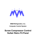
CONTENTS
SAFETY INFORMATION . . . . . . . . . . . . . . . . 2
FOR YOUR SAFETY . . . . . . . . . . . . . . . . . . . . . . 2
SYSTEM OPERATION. . . . . . . . . . . . . . . . . . 2
THERMOSTATS . . . . . . . . . . . . . . . . . . . . . . . . . . 2
INTERMITTENT IGNITION DEVICE . . . . . . . . . . 2
OPERATING INSTRUCTIONS . . . . . . . . . . . . . . . 3
EXPLAIN UNIT FUNCTION . . . . . . . . . . . . . . 4
GENERAL MAINTENANCE. . . . . . . . . . . . . . 4
HEATING SYSTEM INSPECTION . . . . . . . . . . . . 4
AIR FILTERS . . . . . . . . . . . . . . . . . . . . . . . . . . . . 5
BLOWER ASSEMBLY . . . . . . . . . . . . . . . . . . . . . 5
MOTORS . . . . . . . . . . . . . . . . . . . . . . . . . . . . . . . 6
CONDENSER COIL . . . . . . . . . . . . . . . . . . . . . . . 6
REGISTERS . . . . . . . . . . . . . . . . . . . . . . . . . . . . . 6
USER’S, MAINTENANCE
and
SERVICE INFORMATION
MANUAL
3 THRU 12.5 TO N
SINGLE PACKAGE
AIR CONDITIONER
GA S/E L EC T R IC
& ELECTRIC/ELECTRIC
TROUBLESHOOTING . . . . . . . . . . . . . . . . . . 6
BEFORE CALLING A SERVICE TECHNICIAN: . . 6
The “User” must read all sections of this manual and keep the manual for future reference.
FIRE OR EXPLOSION HAZARD
Failure to follow safety warnings exactly could
result in serious injury, death, or property damage.
- Do not store or use gasoline or other flammable
vapors and liquids in the vicinity of this or any
other appliance.
- WHAT TO DO IF YOU SMELL GAS:
•
•
Do not try to light any appliance.
Do not touch any electrical switch; do not use
any phone in your building.
•
Leave the building immediately.
•
Immediately call your gas supplier from a
neighbor’s phone. Follow the gas supplier’s
instructions.
•
If you cannot reach your gas supplier, call the
fire department.
- Installation and service must be performed by a
qualified installer, service agency or the gas
supplier.
1046287-UUM-A-1013
1046287-UUM-A-1013
SAFETY INFORMATION
SYSTEM OPERATION
FOR YOUR SAFETY
THERMOSTATS
•
Make sure that the furnace area is clear and free of
combustible materials, gasoline and other flammable vapors and liquids.
•
Be sure the furnace is clear and free of insulating
material. Examine the furnace area after installation of the furnace or the installation of additional
insulation. Some types of insulation maybe combustible.
•
For proper and safe operation, the furnace needs
air for combustion and ventilation. Do not block or
obstruct air openings on the furnace or the space
around the furnace. Maintain the required unit
clearances.
•
For lighting or shutting down this furnace, refer to
the lighting instructions provided adjacent to the
burners in the unit and also located in this manual
on Pages 7 and 8.
•
A blocked vent roll-out switch is provided in the
burner compartment. This switch is a manual reset.
If the furnace fails to operate, contact a qualified
service technician.
•
Should the gas supply fail to shut off or if overheating occurs, shut off the gas valve to the furnace
before shutting off the electrical supply. Then call a
qualified service technician.
•
Do not use this furnace if any part has been under
water. A flood-damaged furnace is extremely dangerous. Attempts to use the furnace can result in
fire or explosion. A qualified service technician
should be contacted to inspect the furnace and to
replace all gas controls, control system parts, electrical parts that have been wet or the furnace if
deemed necessary.
•
2
Determine the integrity of the installation regarding
the flue gas vent, the return and supply air duct. All
flue gas carrying areas external to the furnace must
be clear and free of obstructions. The external vent
should be attached and physically sound without
holes or excessive corrosion. The return-air duct
connection(s) should be physically sound and
sealed to the furnace casing. The physical support
of the furnace should be sound without sagging,
cracks, gaps with no obvious signs of deterioration.
The burner flames in operation should appear as
detailed in figure 3. The manufacturer recommends
that main burner, ignition device and controls are
inspected by a qualified service technician before
each heating season.
Set your thermostat for either heating or cooling then set it for
the desired temperature. DO NOT ADJUST THE THERMOSTAT RAPIDLY ON AND OFF, OR BACK AND FORTH
FROM HEAT TO COOL. THIS COULD DAMAGE YOUR
EQUIPMENT.
Always allow at least 5 minutes between changes. Find the
temperature that is most comfortable to you and then LEAVE
YOUR THERMOSTAT ALONE. (Exception is for night or
vacation “set back” to conserve energy).
Manually moving the thermostat up or down will not speed up
temperature changes in your rooms. This only causes the
thermostat switch to function at your command rather than
responding to room temperature.
Heat generated by devices other than the furnace may interfere with thermostat performance. Therefore, lamps, radios,
television sets, etc. should not be placed near the thermostat.
FIGURE 1- TYPICAL THERMOSTAT
INTERMITTENT IGNITION DEVICE
This furnace is equipped with an intermittent automatic ignition system. Do Not attempt to manually
relight the burners. Personal injury could result.
When the thermostat calls for heat, gas is supplied and at the
same time, sparking occurs to light the burner. With the
burner lit, the flame sensor rod closes a circuit to the igniter
control which allows the burner to continue to fire.
When the room thermostat is satisfied, the electrical circuit to
the gas valve is opened, closing main burner gas. If the
burner should fail to light, contact your heating contractor or
gas utility for service to insure that proper operating conditions are restored.
Johnson Controls Unitary Products
1046287-UUM-A-1013
INPUT
VENT SAFETY SYSTEM:
The correct heat capacity of the furnace is regulated by the
burner orifices and the gas pressure. The proper orifices are
furnished but the gas pressure regulator must be adjusted by
the installer or gas utility service technician.
This gas furnace is equipped with a manual reset high temperature sensor or rollout switch which in the unlikely event of
a sustained main burner flame rollout will shut off the flow of
gas by closing the main gas valve. The ignition modules will
also be disabled, preventing the flow of gas to the valve. The
switch is located inside the gas heat access panel above the
burner inlet. Flame rollout can be caused by blockage of the
power vent system, improper gas pressure or adjustment. If
this event occurs the furnace will not operate properly. The
gas supply to the furnace should be shut off and no attempt
should be made to place the furnace in operation. The system should be inspected by a qualified service technician.
Refer to Figure 2 for a typical installation.
OPERATING INSTRUCTIONS
TO SHUT DOWN THE FURNACE:
1.
Close the main gas shutoff valve(s).
2.
Turn off the electric power supply.
TO LIGHT THE FURNACE:
100% SHUT OFF:
FIRE OR EXPLOSION HAZARD
The ignition modules are designed for 100% shut-off. If the
furnace fails to ignite after three ignition attempts, the flow of
gas will be shut off and the ignition module will lock out. The
module can be reset by:
Failure to follow safety warnings exactly could
result in serious injury, death, or property damage.
A.
Turning the system switch on the room thermostat to the
“OFF” position and back to the “HEAT” position.
- Do not store or use gasoline or other flammable
vapors and liquids in the vicinity of this or any
other appliance.
B.
Decreasing the set point of the room thermostat below
the temperature in the conditioned space and returning it
to its original setting.
- WHAT TO DO IF YOU SMELL GAS:
C. Opening and closing the unit's main disconnect switch.
•
•
Do not try to light any appliance.
Do not touch any electrical switch; do not use
any phone in your building.
•
Leave the building immediately.
•
Immediately call your gas supplier from a
neighbor’s phone. Follow the gas supplier’s
instructions.
•
If you cannot reach your gas supplier, call the
fire department.
- Installation and service must be per formed by a
qualified installer, service agency or the gas
supplier.
1.
Do not attempt to light manually.
2.
Open the main gas shutoff valve(s).
3.
Adjust the set point of the room thermostat above the
temperature in the space.
4.
Turn on the electric power supply.
5.
The draft fan will operate. After an adequate purge time,
the electric spark igniter will light the burners.
6.
The burners will extinguish and relight automatically
upon the demand of the room thermostat.
FIGURE 2-
Johnson Controls Unitary Products
TYPICAL INSTALLATION
3
1046287-UUM-A-1013
If the furnace continues to lock out, a qualified service technician should be called to determine the cause of the problem.
ELECTRICAL SHOCK, FIRE OR EXPLOSION HAZARD
Failure to follow safety warnings exactly could result
in dangerous operation, serious injury, death or property damage.
Improper servicing could result in dangerous operation, serious injury, death or property damage.
•
•
•
Before servicing, disconnect all electrical power
to furnace.
When servicing controls, label all wires prior to
disconnecting. Reconnect wires correctly.
Verify proper operation after servicing.
In addition, at least once during the heating season, the
owner shall make a visual inspection of the flue outlet for evidence of black soot or blockage of flue outlet by leaves or
other debris. If any soot is found, it is recommended a qualified service technician be called immediately. If any blockage
is found, it must be cleared immediately. After removing the
debris, check the manual reset rollout switch located above
the burner shield and reset as needed. (See Figure 3.)
Check for obvious signs of deterioration of the unit. Check
that the return and supply ducts attached to the unit are
sound and air tight. Check that the unit's physical support,
concrete slab or roof curb, is sound and not in need of repair.
Make sure there are no gaps between the roof curb and the
unit where rain could leak into the building.
Start the furnace. The vent motor should start, the igniter will
start to spark and ignite the burner. If it does not, contact a
qualified service technician for assistance. Check the appearance of the main burner flame. The flame should have a blue
appearance. (See Figure 3.)
ROLL OUT SWITCH
Prior to any of the following maintenance procedures,
shut off all power to the unit to avoid personal injury.
IGNITOR
HEAT EXCHANGER TUBE
EXPLAIN UNIT FUNCTION
When the system is functioning properly, show the owner the
location of all disconnect switches and the thermostat.
Explain how to start and stop the unit and how to adjust temperature settings within the limitations of the system. Advise
that the flue exhaust hood surface and the immediate area
will experience high temperatures during the heating cycle,
and that all unauthorized personnel and debris must be kept
away from this area.
GENERAL MAINTENANCE
In order to insure long and trouble free service from your system, we recommend periodic inspection, cleaning, lubrication
and adjustment by your installing Dealer/Contractor. Be sure
to ask about this service. For those who prefer to do-it-yourself, please follow the instructions listed below to care for
your system.
Snow or debris should not be allowed to accumulate in or
around the unit. Do not permit overhanging structures or
shrubs to obstruct outdoor air discharge, combustion air
inlets or vent outlets on your unit. These provide air for combustion and ventilation. Adequate air is important to the safe
and proper operation of the unit.
GAS
SUPPLY
PIPE
FIGURE 3-
4
BURNER BRACKET
TYPICAL FLAME
BURNER CHECK
Periodically (at least annually at the beginning of each heating season) make a visual check of the main burner flame to
determine if the burners need cleaning.
CLEANING BURNERS
Remove them from the furnace as explained the in BURNER/
ORIFICE INSTRUCTIONS section in the Unit Installation
Instructions. Clean burners with wire brush and vacuum as
needed.
CLEANING FLUE PASSAGES & HEATING ELEMENTS
With proper combustion adjustment, the heat exchanger
tubes of a gas-fired furnace will seldom need cleaning. If the
tubes should become sooted, they can be cleaned as follows:
1.
Remove the burner assembly as outlined in “BURNER/
ORIFICES INSTRUCTIONS” of the unit Installation
Instructions.
2.
Remove the screws holding the flue collector box. Carefully remove the flue collector box.
3.
Remove the flue baffles from the tube interiors.
4.
Using a wire brush on a flexible wand, brush out the
inside of each heat exchanger from the burner inlet and
flue outlet ends.
HEATING SYSTEM INSPECTION
It is the owner's responsibility to insure that an annual inspection of the entire heating portion of the unit is made by a qualified service technician. This should include inspection of the
burner, heating element and flue for any corrosion or soot
accumulation which may require cleaning and also checking
of burner and controls for proper operation.
BURNER FLAME
(BLUE ONLY)
BURNER
Johnson Controls Unitary Products
1046287-UUM-A-1013
5.
Brush out the inside of the flue collector box and the flue
baffles.
6.
Run the wire brush into the flue exhaust tube from the
flue collector end. Do not damage the flue exhaust
screen, remove if necessary.
7.
If soot build-up is particularly bad, remove the draft motor
and clean the wheel and housing.
8.
After brushing is complete, blow away all brushed areas
with air or nitrogen. Vacuum as needed.
9.
Replace parts in the reverse order that they were
removed in Steps 1 through 3.
10. Assure that all seams on the vent side of the combustion
system are airtight. Apply a high temperature (500°F+)
sealing compound where needed.
AIR FILTERS
receive either 1" or 2" filters. Filters can also be installed in
the building at a suitable return air location if an economizer
or outside air accessory is not used. Filters must always be
used. They should be inspected once a month and thoroughly cleaned or replaced if it appears they are beginning to
accumulate excessive dirt.
To install the filters, remove the filter access panel as shown
in Figure 4.
NOTE: Filters must be installed with “Air Flow” arrows pointing inward -- toward the indoor coil. In the event the
spacers in the filter section are removed, they must
be reinstalled in their original position.
Slide filters all the way into the filter racks provided. When
more than one filter in a filter rack is required, they must butt
each other when sliding into position. Replace the filter
access panel.
ZX 3, 4, 5 ton and ZY 3 ton units require 2 filters. All other
units contain four filters. The filter racks on these units will
FIGURE 4-
FILTER ACCESS
BLOWER ASSEMBLY
Even with good filters properly in place, blower wheels and
motors will become dust laden after many months of operation. The entire blower assembly should be inspected annually. If the motor and wheel are heavily coated with dust, they
can be brushed and cleaned with a vacuum cleaner.
These units are supplied with blower shaft bearings that do
not require maintenance but may be lubricated if desired.
Every three years, using a low pressure grease gun, pump
Johnson Controls Unitary Products
grease into the bearing grease fitting until grease just begins
to show at the seals. Do not over lubricate. Use any lithium
base grease recommended for ball bearing service.
Perform all maintenance operations on the blower assembly and motor with electric power disconnected from the
unit. Do not attempt to lubricate bearings with the unit in
operation.
5
1046287-UUM-A-1013
MOTORS
Outdoor fan motors are permanently lubricated and do not
require maintenance.
Ventor motor is factory lubricated for an estimated 10 year
life.
The indoor blower motor features ball bearings that do not
require periodic lubrication. However, if the motor has grease
fittings, periodic lubrication of the motor bearings can extend
the life of components but is optional.
Perform all maintenance operations on the blower motor
with electric power disconnected from the unit. Do not
attempt to lubricate bearings with the unit in operation.
If desired, every three years, using a low pressure grease
gun, pump grease into the bearing grease fitting until grease
just begins to show at the seals. Do not over lubricate. Use
any lithium base grease recommended for ball bearing service.
6
Damage can occur if the bearings are overlubricated. Use
grease sparingly.
CONDENSER COIL
An annual check and cleaning, if necessary, of the outdoor
coil should be done. Cleaning should be as often as necessary to keep the coil clean. Clean any debris and dirt from the
outside coil face with a brush being careful not to damage the
fins. If extremely dirty, a hose can be used to wash the coil
from the inside out while brushing a soapy solution on the
outside.
REGISTERS
Supply and return air registers must be open when the unit is
in operation. Obstructions must not be allowed to block airflow in or out of the registers.
TROUBLESHOOTING
BEFORE CALLING A SERVICE TECHNICIAN:
A.
Check thermostat setting and insure thermostat is calling
for heat or cooling.
B.
Check thermostat for lint, etc.
C.
Check fuses or circuit breakers.
D.
Check filters for excessive dust accumulation.
Johnson Controls Unitary Products
1046287-UUM-A-1013
FIGURE 5-
LIGHTING INSTRUCTIONS FOR ZX04 THRU 07 AND ZY04 THRU 06
Johnson Controls Unitary Products
7
1046287-UUM-A-1013
FIGURE 6-
8
LIGHTING INSTRUCTIONS FOR ZX08 THRU 14 AND ZY07 THRU 12
Johnson Controls Unitary Products
OWNER please have your installer fill in the following information immediately after unit has been installed
and is properly operating.
Installed by __________________________________________________________________________________
Installer’s Address ____________________________________________________________________________
Installation Date ______________________________________________________________________________
Owner’s Name _______________________________________________________________________________
Owner’s Address _____________________________________________________________________________
Equipment installed at (address) _________________________________________________________________
Model Number ____________________________________
Serial Number _____________________________
Distributor from whom the equipment was purchased _________________________________________________
The owner should keep this information in a place where it can be found if needed for warranty purposes.
Subject to change without notice. Printed in U.S.A.
Copyright © 2011 by Johnson Controls, Inc. All rights reserved.
York International Corporation
5005 York Drive
Norman, OK 73069
1046287-UUM-A-1013
Supersedes: Nothing
1046287-UUM-A-1013
10
Johnson Controls Unitary Products