1
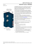
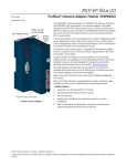
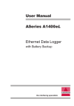
LTX
RF LEVEL SENSOR
Instruction Manual
FOR MODELS
LTX01, LTX02, LTX05
Intempco
LTX01 RF LEVEL SENSOR
USER MANUAL
1
Document No:
LTX - M01 Rev. 1
Issue Date:
April 2005
Software Rev :
Rev. Date :
June 2004
TABLE OF CONTENTS
1.0
PRODUCT OVERVIEW
1.1
1.2
1.3
2.0
INSTALLATION
2.1
2.2
2.3
3.0
Product Features
Description
Specifications
1.3.1 Electrical Specifications
1.3.2 Mechanical Specifications
Probes
Probe Installation
Electrical Installation
2.3.1 Head Mounted Transmitter Connections
2.3.2 DIN RAIL Remote Transmitter Connections
CALIBRATION
3.1
3.2
3.3
3.4
3.5
Current Meter
Reset and Offset functions
Damping Adjust
Two Point Calibration
3.4.1 Calibration L-H
3.4.2 Calibration L-H1
3.4.3 Calibration L1-H1
How to transfer calibration parameters
2
1.0
1.1
Product Features
•
•
•
•
•
•
•
•
1.2
PRODUCT OVERVIEW
Heavy duty industrial design for metallic level tanks
Can be used in all other tanks, metallic or non-metallic, with conductive or nonconductive liquids, by use of a concentric pipe
Continuous loop powered 4-20mA operation
Installed Hockey-puck or Remote DIN Rail mounted transmitters available
Standard ¾” NPT thread connection, others available
Available with non-metallic, stainless or aluminum explosion proof heads
Teflon PFA clad or bare Stainless 316 probe
Accuracy 1% of span for same dielectric
Description
The INTEMPCO series LTX RF Remote Level Sensors are of compact heavy-duty design
with connection head and installed electronics. Two types of electronics are available. Headmounted hockey-puck type microprocessor based 4-20 mA output transmitter is standard.
Also available is head-mounted remote module with DIN Rail transmitter, which can be
installed up to 1000 feet away from the process, where the calibration can be performed.
LTX RF Remote Level Sensors comprise of enclosure with installed or remote electronics,
compression fitting and PFA clad or bare stainless probe The microprocessor-based
electronics convert frequency change, detected by the probe, into a linear, highly accurate 420mA signal. This compact design makes installation and setup a simple task. The advanced
signal conditioning circuitry greatly minimizes the adverse affects of poor dielectric and
material coating on the probe.
LTX-1 RF level transmitters can be used in metallic and non-metallic tanks (with concentric
pipe), stationary or mobile equipment. Ideal for compact tanks of all types, they can be used
in virtually any liquid, conductive or non-conductive. Compact and rugged, LTX Series
sensors cannot be beat in performance. Some level applications include: fuel and oil tanks in
mobile equipment and tanks, water based liquids in most tanks, acids compatible with
Stainless 316 and PFA Teflon, MEK and other solvents, chemical holding tanks.
1.3
Specifications
1.3.1
Electrical Specifications
Supply Voltage:
Output:
Max. Loop Res.:
Calibration:
Accuracy:
Repeatability:
Damping adjust:
12VDC – 36 VDC
4-20mA, loop powered
(Vs-10)/0.02 (i.e. 700Ω at 24VDC)
Via 4 push-button switches non-interactive
Zero & Span
± 1% of full span (Constant dielectric)
± 1% of span
0-30 sec
3
1.3.2
Mechanical Specifications
Enclosure:
Mounting Thread:
Processes Temperature:
Pressure Limits:
Probe Material:
Ambient Temperature:
Alum. Ex. Proof and Stainless (all NEMA 4), PVC
¾” NPT standard. other available
2000C max (3920F)-PFA probe
2000C + Stainless 316 probe
100 psi (7 bar) @ 250C (750F)
50 psi (3.5 bar) @ 1500C (3000F)
14.5 psi (1 bar) @ 2000C (3920F)
PFA Teflon jacketed or bare SS316
-40 to 700C (-40 to 1580C)
2.0
INSTALLATION
Note: Unpack the instrument carefully. Inspect all components for damage. If any damage is
found, please notify a INTEMPCO representative as soon as possible prior to installation.
The INTEMPCO series LTX RF level sensor should be located for easy access for service
and monitoring. Sensor installed transmitter or remote electronics and DIN rail should not be
exposed to temperature below -400C (-400F) or above 700C (1580F). This is very important
when process temperatures are high and heat can conducted up to the enclosure and to the
remote electronics. Special precaution should be made to prevent exposure to corrosive
atmospheres, excessive vibration, shock or physical damage. It is preferable that the LTX is
not installed in proximity to high voltage wires or other sources of high electrical noise.
2.1
Probes
For conductive liquids, such as water and acids PFA Teflon coated probes are always used.
For non-conductive liquids, such as oils, diesel fuel and MEK solvents PFA Teflon coated
probes can also be used. Bare stainless probes are used for high temperature applications.
The probe length is customer specified for the height of material desired to be measured.
2.2
Probe Installation
Standard probe entry in to a tank is via a 3/4" NPT opening. Other fitting sizes are available
as options.
TO SCREW IN PROBE (THREADED ENTRY) USE WRENCH ON LOWER HEX ONLY. DO
NOT USE A PIPE WRENCH. Use pipe sealent as required.
LTX installation considerations depend on the type of application. The following are the main
points to consider while installing the probe.
(a) Reference ground: This is VERY IMPORTANT and is typically the metal walls of the
tank. For non-metallic tanks, a concentrically shielded probe is required in which case the
shield provides its own ground. IMPORTANT: For standard threaded entry and flange entry
probes (without concentric shield), mare sure the fittings are clean to ensure (by use of OHM
meter) a GOOD ELECTRICAL CONNECTION BETWEEN THE PROBE HEAD
ENCLOSURE AND THE TANK (reference GND on the remote transmitter, GREEN WIRE).
4
(b) The distance between the probe and the ground reference: This only applies to
standard probes without concentric shields. The closer the distance to the tank wall, the
greater the sensitivity of measurement.
(c) Parallelism between the probe and the reference ground: This only applies to
standard probes without concentric shields. The probe should be installed parallel to the tank
wall to insure a linear output.
(d) Location: Avoid installing LTX type probes in nozzles or recesses where material can
accumulate and give false readings.
(e) The measurement accuracy: The accuracy is affected by the temperature change of the
material in the tank. The percentage of error is depends on the material used in the tank. If
the temperature change is excessive, temperature correction will be required. Contact
INTEMPCO representative for more information.
(f) Mobile objects in the tank: Moving objects in the tank close to the non-shielded probe
such as agitator blades, moving baffles etc. appear as moving ground references to a
capacitance probe and could cause measurement errors. In applications where these objects
are present, a concentrically shielded probe, must be used.
5
2.3
Electrical Installation
2.3.1
Head Mounted Transmitter Connections (Refer Figure 1.)
Note: All wiring between the power supply and the head mounted hockey-puck transmitter should be
done with 18 AWG to 22 AWG wiring. A shielded twisted pair cable may be used.
CAUTION: Units are designed to operate on 12 to 36 VDC power only. Application of 110 VAC
will destroy the instrument.
1.
2.
3.
4.
5.
6.
7.
Make sure the power source is turned OFF
Remove the head cover and pull supply wires through the conduit connection.
Verify that the positive side of the probe (Blue wire) is connected to the “P” terminal of the
transmitter and that the probe reference ground (Green Wire) is connected to the “G” terminal of
the transmitter.
Replace the transmitter enclosure (head) cover until time to calibrate.
Connect the positive side of the loop to the “+” terminal of the transmitter.
Connect the loop current meter in series with the negative supply wire as follows:
a)
Negative “-“ transmitter wire to the positive meter terminal.
b)
Negative “-“ meter terminal to negative “-“ power source terminal.
Turn ON the power. The meter may read anywhere on the scale at either end. This is normal
until calibration has been completed. Proceed to the calibration instructions.
Note: Leave the shield unattached at the transmitter and the power supply. If the output signal is
noisy connect the shield to ground of the power source.
Figure 1. Head Mounted Transmitter
6
2.3.2
DIN RAIL Remote Transmitter Connections (Refer Figure 2.)
Note: All wiring between the power supply and the DIN rail transmitter should be done with 18 AWG to
22 AWG wiring. A shielded twisted pair cable may be used. Between DIN RAIL transmitter and the
remote electronic module installed in the head, use a shielded twisted cable with 3 or 4 conductors,
18AWG to 22 AWG. Cable runs of up to 300 M (1000 ft) are permitted.
CAUTION: Units are designed to operate on 12 to 36 VDC power only. Application of
110 VAC will destroy the instrument.
Figure 2. DIN-RAIL Transmitter with Head-Mounted Remote Module
The Remote Module (RM) is normally installed inside the enclosure or head of the LTX level sensor.
The “Blue Wire” (Probe +) and “Green Wire” (Probe Ref. Ground) are factory connected. Verify that
they are connected and do not connect any other wires to these two terminals.
1. Make sure the power source is turned OFF.
2. Connect the “D ” terminal of RM (Red Wire, power Vr) to the terminal “D ” of the DIN-RAIL
Transmitter.
3. Connect the “E ” terminal of RM (Black Wire, ground Gr) to the terminal “E ” of the DIN-RAIL
Transmitter.
4. Connect the “F ” terminal of RM (White Wire, signal S) to the terminal “F ” of the DIN-RAIL
Transmitter.
5. Connect the “G ” terminal (“+ ” loop) of the DIN RAIL to the positive side of the power supply.
6. Connect the “J ” terminal (“- ” loop) of the DIN RAIL to the positive side of the meter.
7. Connect the negative of the power supply to the negative of the meter.
Note:
Leave the shield unattached at the transmitter and the power supply. If the output signal
is noisy connect the shield to ground of the power source.
7
3.0
CALIBRATION
Install the LTX RF Level Sensor as per installation instructions in section 2.0. In order
to perform the calibration it is very important to be able to vary the level in the tank
(empty or fill). If this cannot be done, proper calibration is not possible.
Decrease the level in the tank until only about 1 to 2 inches of the probe are covered
or to the minimum level possible.
3.1
Current Meter
In order to calibrate the transmitter, you must use the loop current meter (as shown in Figure
1 or 2). It should read in the range of 1.00 to 25.00 mA, with a resolution of 0.01mA. Using a
current meter with less resolution will somewhat reduce the calibration accuracy. To calibrate
the instrument:
1. Remove cover of the enclosure head (in case of Head Mounted version).
2. Connect the loop current meter as per instructions in wiring section meter (as
shown in Figure 1 or 2).
3. Turn the power ON. The loop current should now be in the range of 1.5 mA to 38
mA, which is normal at this point.
If the tank is nearly empty or somewhat below the mid-level and the output reads between
1.5 to 12 mA, press Z UP or Z DW push buttons. If the output varies accordingly, the Reset
and Offset functions, as in section 3.2, needs not be performed. If pressing Z UP and Z DW
push buttons does not vary the output, go to section 3.2.
3.2
Reset and Offset functions
OFFSET and RESET functions (or values) are factory set. They may have to be changed by
the customer in special cases only. Follow the procedure below.
There may seem to be a malfunction with the transmitter when the 4-20 mA power loop is
activated for the first time. The mA reading may be below 4 mA or above 20 mA and
pressing the Z and S push buttons does not change the output.
Note : Push button may have to be depressed for up to a minute before the value may
change.
The OFFSET function may have to be performed. To re-OFFSET the transmitter, lower the
level in the tank to below the probe (material is not in contact with the probe, this is very
important). Press Z UP and S UP push buttons at the same time, then release in 2 to 3
seconds. The transmitter should not show a default value close to 4 mA.
In very rare cases, a problem still may persist. This is because the values of the minimum
and maximum are not properly distributed. The RESET function may have to be performed.
To RESET the transmitter, simply press Z DW and S DW push buttons at the same time,
then release the two push buttons after 2 to 3 seconds. Then re-OFFSET the transmitter as
per instructions above. The transmitter should now show a default value close to 4 mA.
8
Important Notes:
(a) The OFFSET function has to be performed with the tank empty.
(b) If a RESET function is to be performed by the customer, then the factory OFFSET
value is automatically cancelled. So, the OFFSET function should always be
applied after a RESET function.
3.3
Damping Adjust
This feature, primarily designed for agitated tanks is factory set at 0 sec. (max. CW, neg.
direction) via a single turn pot. This sets a time delay on the output signal. The time delay
range is 0-10 sec. approx. For non-agitated tanks a zero setting is fine. For agitated
tanks, increase the time delay setting by turning the pot CCW. The Damping adjust can
also be used as an output filter. In certain applications, such as, poorly grounded tanks in
electrically noisy environments and/or tanks containing a low dielectric (non-conductive
/oil based media), the 4-20mA output, may oscillate. In that case, increase the DAMP
ADJ by turning the pot in CCW direction, and observe the output; it should stabilize.
NOTE: The DAMP ADJ pot must be turned back to minimum time delay, max. CW
(neg.) direction, when performing the calibration (by pressing Z or S buttons).
3.4
Two Point Calibration – Level Increase
Three calibration procedures are described here. Follow the one, which best suits your
application. Note the following definitions used in the calibration procedures, referring to
Figure 3.
L=
L1 =
H1 =
H=
the level of material which corresponds
to 4.00 mA of loop current, i.e., the 0%.
a material level higher than L.
a material level higher than L1, but less than H.
the level of material in the vessel which
corresponds to 20.00 mA of loop current, i.e.,
the 100% level.
Note: To avoid the possibility of a “dead zone”, L
must be at least one inch above the end of the
probe for conductive media and two inches above
for non-conductive media.
Figure 3.
3.4.1 CALIBRATION L - H = when material in tank can be set to L (0%) and H (100%).
3.4.2 CALIBRATION L - H1 = when material in tank can be set to L (0%) and H1 less
than 100%).
3.4.3 CALIBRATION L1 - H1 = when material in tank can be set to L1 (greater than 0%) and
H1 (less than 100%).
9
NOTE: Calibration procedure L-H gives the most accurate results and is the recommended
procedure in all cases.
The following are the important points for all calibration procedures:
(a) Set the “Damping” to the minimum value, CW direction.
(b) If there is no change in output when performing “Zero” adjustment first, perform a
“Reset” and “Offset”, with the tank empty or at L (Figure 3.) level, before starting
calibration.
(c) Perform the “Zero” adjustment first.
(d) During the first calibration, even if the “Zero” value is correct always press Z-UP or ZDWN at least one or two times and re-adjust to the correct value. That will allow the
transmitter to record that value as its “Zero ” reference for the non-interactive
calibration feature.
(e) Never press Z-UP or Z-DWN push buttons when the tank is full or more than 50% full.
That will cause the transmitter to record that value as its “Zero” reference and will
affect the calibration.
(f) When calibration is finished, be sure there is nothing that can interfere physically with
the calibration push buttons.
(g) When calibration is completed, avoid moving or touching the probe wire (Blue). That
may cause an offset on the output reading.
(h) After the first calibration, if a small re-adjustment is necessary, use Z-UP or Z-DWN if
the tank is at less then 50% full and S-UP or S-DWN if higher than 50% full.
(i) When calibration is completed, apply silicone over all the connectors to prevent
corrosion where applicable.
3.4.1
Calibration procedure L-H
THE ZERO, TANK IN L (LOW) STATE, MUST ALWAYS BE CALIBRATED FIRST.
Turn the DAMP ADJ pot to max CW (neg.) direction
1. Fill the tank to its L (0%) level (with probe covered).
2. Depress UP or DW buttons on Z until meter reads 4.00 mA. Do not change the zero
controls from now on. If changed, the material will have to be returned to the L (0%)
level.
Note: If a 4.00 mA value cannot be reached, then perform RESET and OFFSET
functions as explained in section 3.2.
3. Fill the tank to the desired H (100%) level.
Note: The loop current may not rise in proportion to the rising material level in tank.
Instead it may rise more rapidly or more slowly than the material level. The span, S, UP
or DW buttons may be used occasionally to maintain the loop current approximately
proportional to the tank filling or just below the 20.00 mA reading.
4. After the tank has been filled to H (100%), depress SPAN UP or DW buttons as
required to obtain a meter reading of 20.00 mA. If 20.00 mA reading has been
obtained, the calibration is complete.
10
Note: If a 20.00 mA value cannot be reached, then perform RESET and OFFSET
functions as explained in section 3.2 and re-start the calibration.
3.4.2
Calibration procedure L-H1
THE ZERO, TANK IN L (LOW) STATE, MUST ALWAYS BE CALIBRATED FIRST.
Turn the DAMP ADJ pot to max CW (neg.) direction
1. Fill the tank to its L (0%) level (with probe covered).
2. Depress UP or DW buttons on Z until meter reads 4.00 mA. Do not change the zero
controls from now on. If changed, the material will have to be returned to the L (0%)
level.
Note: If a 4.00 mA value cannot be reached, then perform RESET and OFFSET
functions.
3. Fill the tank to the highest point possible (under 100%), and record this level as H1.
The most accurate calibration will be obtained with the greatest separation between L
and H1.
Note: The loop current may not rise in proportion to the rising material level in tank.
Instead it may rise more rapidly or more slowly than the material level. The SPAN, S- UP
or S-DW buttons may be used occasionally to maintain the loop current approximately
proportional to the tank filling or just below the 20.00mA reading.
4. To determine the loop current at H1 level use the following formula :
mA =
( H1 − L)
x16 + 4
( H − L)
Example:
L = 12 ” (30.5 cm) from the bottom of the tank
H1 = 72” (183 cm) from the bottom of the tank
H = 96 ” (244 cm) from the bottom of the tank
mA =
(72 − 12)
x16 + 4 = 15.43
(96 − 12)
The correct loop current is 15.43mA. Depress SPAN S-UP or S-DW buttons as
required to obtain a meter reading of 15.43 mA. If 15.43mA reading has been
obtained, the calibration is complete.
Note: If a 15.43mA value cannot be reached, then perform RESET and OFFSET
functions and re-start the calibration.
3.4.3
Calibration procedure L1-H1
THE ZERO, TANK IN L1 (LOW) STATE, MUST ALWAYS BE CALIBRATED FIRST.
Turn the DAMP ADJ pot to max CW (neg.) direction
11
1. Fill the tank to L1, some point above 0% level and record this level as L1 (Refer
Figure 3.). To determine the loop current at L1 level use the following formula:
mA =
( L1 − L)
x16 + 4
( H − L)
Example:
L = 12” (30.5 cm) from the bottom of the tank
L1 = 24” (61 cm) from the bottom of the tank
H = 96” (244 cm) from the bottom of the tank
mA =
( 24 − 12)
x16 + 4 = 6.28
(96 − 12)
The correct loop current is 6.28mA.
2. Depress Z-UP or Z-DW buttons on ZERO until meter reads 6.28mA. Do not change
the ZERO controls from now on. If changed, the material will have to be returned to
the L (0%) level.
Note: If a 6.28 mA value cannot be reached, then perform RESET and OFFSET
functions.
3. Fill the tank to the highest point possible (under 100%), and record this level as H1.
The most accurate calibration will be obtained with the greatest separation between L
and H1.
Note: The loop current may not rise in proportion to the rising material level in tank.
Instead it may rise more rapidly or more slowly than the material level. The SPAN, S-UP
or S-DW buttons may be used occasionally to maintain the loop current approximately
proportional to the tank filling or just below the 20.00mA reading.
4. To determine the loop current at H1 level use the following formula :
mA =
( H1 − L)
x16 + 4
( H − L)
Example:
L = 12” (30 cm) from the bottom of the tank
H1 = 72” (183 cm) from the bottom of the tank
H = 96” (244 cm) from the bottom of the tank
mA =
(72 − 12)
x16 + 4 = 15.43
(96 − 12)
The correct loop current is 15.43mA.
5. Depress SPAN S-UP or S-DW buttons as required to obtain a meter reading of 15.43
mA. If 15.43mA reading has been obtained, the calibration is complete.
Note: If a 15.43 mA value cannot be reached, then perform RESET and OFFSET
functions and re-start the calibration.
12