1
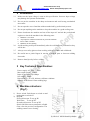
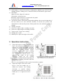
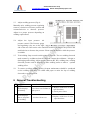
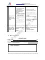
AA Portable Power Corp
www.batteryspace.com, Email: [email protected]
MSK 320A
User Manual
1
AA Portable Power Corp
www.batteryspace.com, Email: [email protected]
Table of content
1
Overview: ............................................................................................................ 3
2
Precaution ........................................................................................................... 4
3
Key Technical Specification: .......................................................................... 4
4
Machine structure: (Fig.1)............................................................................... 4
5
Operation instruction:...................................................................................... 5
6
General Troubleshooting ................................................................................ 6
7
Warranty Card .................................................................................................... 7
8
Instructions for Warranty:............................................................................... 8
9
Tips for Warranty: ............................................................................................. 8
2
AA Portable Power Corp
www.batteryspace.com, Email: [email protected]
1 Overview:
MSK-320A Microcomputer Control Capacitive Discharge Spot Welder (CD Welder),
a capacitive resistance spot welders, is the most popular capacitive discharge spot
welder driven by compressed air, which is designed for the production of the world’s
high-class battery manufacturer (NiMH, NiCd, Li-Ion,LiMnNi,LifePO4, NMC) with
more reliable and consistent welding than AC pulse. It can be used for AA / AAA / C /
D / F / M / 10440 / 14430 /14500 / 14650 / 17500 / 18650 / 26650 / 38120 / 40160 sizes
of batteries. Key characteristics include:
1.1
Excellent choice when the welding application require a rapid rise time and high
energy discharge
1.2
Digital LCD control panel.
1.3
Compact and attractive dimension.
1.4
Most cost-effective welding solutions for fine-spot resistance welding.
1.5
Quick energy release for welding highly conductive metals such as copper
1.6
Small heat affected weld zones
1.7
Repeatable energy release independent of line voltage fluctuations
1.8
Capable of extremely fine energy adjustment
1.9
Homogeneous welding spot, small spark, no black spots and stable welding
current.
1.10 Fully eliminates the phenomenon of low voltage or condensation occurred to
lithium batteries after welding and serves as ideal equipment for you to produce
assembled batteries.
1.11 Microcomputer single chip control, the welder may achieve single-pulse,
double-pulse or multi-pulse welding.
1.12 All parameters are set via microcomputer. Adopts LCD display and keypad
adjustment, resulting in accuracy, visualization and easy of operation.
1.13 Independently adjust for the pressure of two welding probes, ensuring stable and
reliable welding pressure.
1.14 Optoelectronic welding switch, which can eliminate the need of changing
switches for similar welding machines.
1.15 Quick and immediate for machine learning and use
1.16 Suitable for 0.03mm ~ 0.2mm welding lugs
3
AA Portable Power Corp
www.batteryspace.com, Email: [email protected]
2 Precaution
2.1
Make sure the input voltage is same as this specification. Incorrect input voltage
may damage the operator and machine.
2.2
Do not put the machine in the damp environment and avoid strong mechanical
movement.
2.3
Do not open the case of machine without authorized by professional persons..
2.4
Do not put anything on the machine to keep the machine in a good cooling state.
2.5
Please shut down the machine and cut off the input AC and ask the professional
engineer to check the machine in the following state:
a.
b.
c.
d.
Machine is over heat.
Any liquid or conductor materials are put in the machine.
Power cable is broken
Machine can not running.
2.6
Avoid touching weld spots immediately after the weld has been performed as they
will be hot.
2.7
Always wear safety glasses when working with spot welders and weld heads.
2.8
Be careful not to pinch fingers in moving weld head parts or between welding
electrodes.
2.9
Remove hand jewelry before welding.
3 Key Technical Specification:
Power supply: AC 220V 50Hz
Max output power: l0KVA
Input air pressure: 0.1-0.8Mpa
Net weight: 45KG
Dimension (L x W x H): 600mm x 450mm x 600mm
Suitable for 0.03mm-0.5mm welding lugs
4 Machine structure:
(Fig.1)
1) Power switch: Push down to switch on and
push again to switch off.
2) Keypad:
First weld current: To set up BI
Weld Time: To set up WT
Second weld current: To set up WI
Switch: Shift the state to pneumatic or Pedal.
Clear: clear the previous configuration. The
welding counters zero clearing.
4
AA Portable Power Corp
www.batteryspace.com, Email: [email protected]
3) LCD display: It shows the previous configuration. Machine type, BI, WT, WI;
Welding counters, welding curve, Connection state (left: Pneumatic; right: Pedal).
4) Rear Panel:
Input AC socket: Input AC connector.
Fuse holder: A 10A fuses in it.
Pneumatic switch connector: To connect the foot pedal.
Air pressure inlet: Air pressure input.
5) Air pressure control: The Pressure gauge and regulating valve are on the right side of
the case. Pull out the valve and turn clockwise to increase the pressure and
anticlockwise to decrease the pressure. Please push in the valve while the pressure is
suitable.
6) Welding electrode
7) Setscrew to adjust width of welding electrode.
8) Setscrew to adjust height of welding electrode.
9) Touch switch: Used to start welding.
10) Welding device table.
11) Handle pin to adjust the height of the table.
5 Operation instruction:
5.1
5.2
Adjust the height of welding electrodes (See
Fig.2): Use a wrench to unscrew Screw 8 for
adjusting the height of welding electrode.
Adjust (or replace) the length protruding
under the electrode (usually 20mm,
excessive length may cause welding
electrode to distort) and retighten the screw.
Use a wrench to unscrew Screw 7 for
adjusting the width of the welding
electrodes. Adjust the two welding
electrodes to optimal distance depending on
the width of welding electrodes and then
retighten the screw.
Note: It is very important to make sure the electrodes are separate.
Adjust the height of the device table
(Fig.3): Twist the handle pin 11.
Adjust the batteries and welding
electrodes to optimal distance
(normally 4mm) and reverse twist the
handle pin 11 to tighten the device
table.
5
AA Portable Power Corp
www.batteryspace.com, Email: [email protected]
5.3
Adjust welding pressure (Fig.4):
Manually twist welding pressure regulating
setscrew, clockwise to increase pressure and
counterclockwise to decrease pressure.
Adjust it to proper pressure depending on
welding requirements.
5.4
Adjust the input pressure: Air
pressure control: The Pressure gauge
and regulating valve are on the right
side of the case. Pull out the valve and turn clockwise to increase the pressure and
anticlockwise to decrease the pressure. Please push in the valve while the pressure
is suitable.
5.5
Trial welding: Step on touch switch to lower electrode. The two welding electrode
make contact by weldment when the electrode contact the weldment . It begin to
discharging and welding, Adjust welding current (BI, WI), welding time, welding
electrode pressure and air pressure to make welding status to achieve optimal
welding effect.
5.6
To ensure excellent welding quality, frequent maintenance should be conducted
on the welding electrodes. Use small sand paper to make the tips of welding
electrodes even and smooth.
6 General Troubleshooting
No
Symptom
Possible cause
Solution
1
LCD displays
at startup.
Fuse blown out. Failure in
input power.
1. Replace with fuses of same
specifications.
2. Check power lines.
1.10A fuse blown out.
2
LCD displays
but no response
in welding.
1. Replace with fuses of same
specifications.
6
AA Portable Power Corp
www.batteryspace.com, Email: [email protected]
3
Power indicator
lights up and
display is good
but no welding
spark.
1. Air pressure too low.
2. Parameters for
welding current set too
low.
3. Excessive gap
between
lower surface of welding
electrode and batteries.
4. Wires connecting
welding switch broken.
5. Optoelectronic switch
damaged.
6. If working indicator
does not light up or
flicker, it may be caused
by power interference.
1. Pressure for w elding
1. Increase air pressure.
2. Increase welding current.
3. Adjust the gap between
batteries and the surface of
welding electrode to about
3-4mm.
4. Connect wires in compliance
with Fig.1
6. Switch power off and switch
it on again.
1. Increase welding pressure.
electrode too low.
2. File the surface of welding
2. Foreign matter on the
electrode even and smooth with
lower side of welding
a small file.
electrode.
4
3. User proper welding
3. Incorrect welding
material.
material.
Note: In case failure remains unsolved please contact manufacturer for maintenance.
In welding, it is
easy to ignite
and even burn
battery casing.
7 Warranty Card
Warranty card
Customer Name:
Tel:
Address:
ProductName:
_:Model & Specifications:
Date of Delivery:
Product No:
Failure descriptions:
Please stamp your purchase invoice on this page and send a copy to our After-sale
7
AA Portable Power Corp
www.batteryspace.com, Email: [email protected]
Dept to establish information file. Keep the original for yourself. We promise a
one-year warranty period for our product commencing on the date of delivery. In
case any mechanical failure occurs during this period, please complete the copy with
such detailed information as your company name, address and failure symptoms and
fax a copy to our company or call us to describe detailed situations, and we will
provide onsite services immediately. In case of mechanical failure, it is
recommended to first refer to the User Manual as well as the instructions and Tips
on the following pages.
Stamp Invoice Here
8 Instructions for Warranty:
1. Please refer to this User Manual before using this product and/or when
encountering any failure (See "General Troubleshooting").
2. In case of enquiry or normal maintenance, please present the Warranty Card and
invoice, and contact our corresponding technicians for inquiry and maintenance.
3. For warranted maintenance, please fax your Warranty Card to our company and call
us describing your company name, address, phone number, product model, number
and date of delivery as well as failure symptom.
9 Tips for Warranty:
1. We provide free maintenance for our equipment for one year commencing on the
date of delivery. Our warranty covers failure arising from normal use within such
period.
2. We shall not be held responsible for failure arising from improper operation or
intentional damage. However, we may provide paid services in this case.
8
AA Portable Power Corp
www.batteryspace.com, Email: [email protected]
3. In case of maintenance for equipment after our one-year warranty period (or for
equipment provided by other companies), we will charge normally for such
maintenance.
In this case,
we will provide three-month warranty for such
replaced parts.
4. Welding electrodes are quick-wear parts and their service life 1s
associated with welding material, its shape and size, operating methods
and some other factors. Our warranty does not cover any damage to the welding
electrodes.
5. Our warranty does not cover any of the following circumstances:
a) No Warranty Card and/or invoice are available.
b) The Warranty Card and/or invoice are obliterated and are not in line with the
product code.
c) Damage arising from improper use, erroneous operation or unauthorized
retrofitting.
d) Damage caused due to use of components made by other manufacturers.
e) Damage caused by unexpected factors.
f) Expiration of the Warranty Period.
g) Failure to make full payment as scheduled by the contract.
9