1
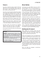
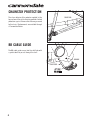
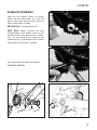
127398
READ THIS SUPPLEMENT AND YOUR CANNONDALE BICYCLE OWNER’S MANUAL.
Both contain important safety information. Keep both for future reference.
SUPERX OWNER’S MANUAL SUPPLEMENT
WARNING
CANNONDALE USA
CANNONDALE EUROPE
CANNONDALE UK
Cycling Sports Group, Inc.
172 Friendship Road,
Bedford, Pennsylvania, 15522-6600, USA
(Voice): 1-800-BIKE-USA
(Fax): 814-623-6173
[email protected]
Cycling Sports Group Europe, B.V.
mail: Postbus 5100
visits: Hanzepoort 27
7570 GC, Oldenzaal, Netherlands
(Voice): +41 61.4879380
(Fax): 31-5415-14240
[email protected]
Cycling Sports Group
Vantage Way, The Fulcrum,
Poole, Dorset, BH12 4NU
(Voice): +44 (0)1202 732288
(Fax): +44 (0)1202 723366
[email protected]
CANNONDALE AUSTRALIA
CANNONDALE JAPAN
WWW.CANNONDALE.COM
Cycling Sports Group
Unit 8, 31-41 Bridge Road
Stanmore NSW 2048
Phone: +61 (0)2 8595 4444
Fax: +61 (0) 8595 4499
[email protected]
Namba Sumiso Building 9F,
4-19, Minami Horie 1-chome,
Nishi-ku, Osaka 550-0015, Japan
(Voice): 06-6110-9390
(Fax): 06-6110-9361
[email protected]
© 2011 Cycling Sports Group
127398 (08/11)
010_OMS_SUPERX_Cover_RZ.indd 2
SUPERX.
OWNER’S MANUAL SUPPLEMENT.
18.08.11 11:48
127398.PDF
SAFETY INFORMATION
Important Composites Message
About This Supplement
Cannondale Owner’s Manual Supplements provide
important model specific safety, maintenance, and
technical information. They are not replacements for
your Cannondale Bicycle Owner’s Manual.
This supplement may be one of several for your bike.
Be sure to obtain and read all of them.
If you need a manual or supplement, or have a question
about your bike, please contact your Cannondale
Dealer immediately, or call us at one of the telephone
numbers listed on the back cover of this manual.
You can download Adobe Acrobat PDF versions of any
Cannondale Owner’s Manuals or Supplements from our
website: http://www.cannondale.com/.
■ This manual is not a comprehensive safety or
service manual for your bike.
■ This manual does not include assembly
instructions for your bike.
■ All Cannondale bikes must be completely
assembled and inspected for proper operation by
a Cannondale Dealer before delivery to the owner.
WARNING
This supplement may include procedures beyond
the scope of general mechanical aptitude.
Special tools, skills, and knowledge may be
required. Improper mechanical work increases the
risk of an accident. Any bicycle accident has risk
of serious injury, paralysis or death. To minimize
risk we strongly recommend that owners always
have mechanical work done by an authorized
Cannondale retailer.
08/11
WARNING
Your bike (frame and components) is made from
composite materials also known as “carbon fiber.”
All riders must understand a fundamental reality
of composites. Composite materials constructed of
carbon fibers are strong and light, but when crashed or
overloaded, carbon fibers do not bend, they break.
For your safety, as you own and use the bike, you must
follow proper service, maintenance, and inspection of all
the composites (frame, stem, fork, handlebar, seat post,
etc.) Ask your Cannondale Dealer for help.
We urge you to read PART II, Section D. “Inspect For
Safety” in your Cannondale Bicycle Owner’s Manual
BEFORE you ride.
YOU CAN BE SEVERELY INJURED, PARALYZED OR KILLED
IN AN ACCIDENT IF YOU IGNORE THIS MESSAGE.
Intended Use
ASTM F2043
For off-road
riding and
jumps less than
12” (30cm)
The intended use of all models
is ASTM CONDITION 2, GENERAl
purpose riding.
WARNING
UNDERSTAND YOUR BIKE AND ITS INTENDED USE.
USING YOUR BIKE THE WRONG WAY IS DANGEROUS.
Please read your Cannondale Bicycle Owner’s
Manual for more information about Intended Use
and Conditions 1-5.
1
Inspection & Crash Damage Of
Carbon Frames/Forks
Bicycle Repair / Work Stands
The clamping jaws of a bike stand can generate a
crushing force strong enough to seriously damage your
frame.
WARNING
NOTICE
AFTER A CRASH OR IMPACT:
Inspect frame carefully for damage (See PART II, Section
D. Inspect For Safety in your Cannondale Bicycle Owner’s
Manual. )
Do not ride your bike if you see any sign of damage, such
as broken, splintered, or delaminated carbon fiber.
ANY OF THE FOLLOWING
DELAMINATION OR DAMAGE:
■
■
■
■
MAY
INDICATE
A
An unusual or strange feel to the frame
Carbon which has a soft feel or altered shape
Creaking or other unexplained noises,
Visible cracks, a white or milky color present in
carbon fiber section
Continuing to ride a damaged frame increases the
chances of frame failure, with the possibility of injury
or death of the rider.
Repainting Or Refinishing
WARNING
Repainting, painting over, retouching, or refinishing
your frame or fork can result in severe damage
leading to an accident. You can be severely injured,
paralyzed or killed.
Refinishing chemicals : Solvents, and strippers can
attack, weaken, or destroy the important composite
chemical bonds holding your frame together.
Using abrasives or sanding the frame/fork
structure, original paint, decals, or coatings
through the use of mechanical actions such as
plastic or glass bead blasting or other abrasive
methods such as sanding or scraping can remove
frame material or weaken it.
2
Never place your bike in a bike stand by clamping the
frame.
Place your bike in a stand by extending the seat post and
positioning the stand clamp on the extended seat post.
Don’t extend beyond the MINIMUM INSERT line marked on
the seat post.
Since your carbon seat post can also be damaged by
clamping force, adjust the stand clamp for the minimum
clamping force needed to secure the bike.
Also, before clamping, clean the post and protect the seat
post finish with a rag.
If you have an old un-used seat post, use it instead of
your regular post to mount your bike in a stand.
Tightening Torques
Correct tightening torque for the fasteners (bolts, screws,
nuts) on your bicycle is very important to your safety. Correct
tightening torque for the fasteners is also important for the
durability and performance of your bicycle. We urge you to
have your Dealer correctly torque all fasteners using a torque
wrench. If you decide to torque fasteners yourself always use
a torque wrench.
Find Tightening Torque Information
The wide range of bicycle models and components used means that
a listing of tightening torque would be out of date by the time it was
published. Many fasteners should be installed with a thread locking
adhesive such as Loctite®.
To determine correct tightening torque and any adhesive application for
a fastener we ask you to check:
• Markings on the component. Many components are
marked. On-product marking is becoming common.
•
Torque specs in the component
instructions shipped with your bicycle.
manufacturers
•
Torque specs listed on the websites of component
manufacturers.
•
With your Dealer. Dealers have access to current data and
have experience with correct torque for most fasteners.
127398.PDF
Trainers
Water Bottles
If you ride a trainer that requires removal of the front
wheel and clamps the fork dropouts: Be sure your fork
quick release is tight! Relative movement will wear
parts, weaken and damage your bike.
Side impacts to a water bottle or cage can result in
damage threaded inserts due to the leverage on a
very small area. In a crash, certainly the last thing
you should be worried about is saving the threaded
inserts in your frame. However, when you are storing or
transporting your bike, take steps to prevent situations
where a water bottle may be hit or bumped by a strong
force that would cause damage. Remove bottle and
cage when you are packing your bike for travel.
If you ride a trainer that holds the bike up by clamping
the rear quick release between two cones: Take off the
nice, lightweight quick release that came with your
bike. Substitute a heavy, classic all steel quick release
and clamp it tight! Relative movement will wear parts,
weaken and damage your bike. Note that many modern
quick releases will not fit the clamping cones in this
kind of trainer because their shapes are incompatible.
If you ride a trainer a lot, consider using an old bike:
Corrosion from sweat will take it’s toll. Weight is
irrelevant. Save wear on your expensive components.
Periodically check the attachment of the bottle cage;
tighten the cage bolts if necessary. Don’t ride with a
loose bottle cage. Riding with loose cage bolts can
produce a rocking motion or vibration of the attached
cage. A loose cage will damage the insert and possibly
lead to the inserts to pull out. It may be possible to
repair a loose insert, or install another insert only if the
frame is undamaged. Replacement requires the use
of a special tool. If you notice damage to the threaded
insert, please ask your Cannondale Dealer for help.
Ask you dealer for help with trainers, the right one and
the correct way to use it.
Building Up A Frameset
Be particularly cautious with a carbon frame or fork.
Carbon is relatively soft, not abrasion resistant. If there
is any relative movement, carbon will wear quickly.
NOTICE
TRAINERS - Improperly mounting a bike in a trainer,
or using one that is not compatible with your
particular bike frame can cause serious damage.
WATER BOTTLES - An impact, crash, or loose bottle
cage can result in damage to your frame.
This kind of damage is not covered by the
Cannondale Limited Warranty.
Before building up a frameset, consult with your
Cannondale Dealer and the component manufacturers,
and discuss your riding style, ability, weight, and
interest in and patience for maintenance.
Make sure the components chosen are compatible with
your bike and intended for your weight and riding style.
Generally speaking, lighter weight components have
shorter lives. In selecting lightweight components, you
are making a trade-off, favoring the higher performance
that comes with less weight over longevity. If you
choose more lightweight components, you must inspect
them more frequently. If you are a heavier rider or have
a rough, abusive or “go for it” riding style, buy heavy
duty components.
Read and follow the component manufacturers
warnings and instructions.
3
SERIAL NUMBER
The serial number locatded on the bottom
bracket. It is a 7-character barcode. Use this
serial number to registration your bike. See your
Cannondale Bicycle Owner’s Manual for more
information on warranty registration.
Other codes on the BB shell are related to
production including model year , frame type,
frame size, and color coding. The same product
code may appear on many bikes and does not
uniquely identify your frame.
SERIAL NO.
PRODUCT CODE
SEAT POST
SEAT BINDER
KP217/
Use a high-quality carbon gel to install and
maintain the seat post. Cannondale kit KF115/
is a small quantity, enough for two or three
applications.
1. Clean the inside of the seat tube. Wipe it out
with a dry clean towel.
2. Apply a generous amount carbon gel to the
inside of the clean seat tube and to the
seat post. A small nylon brush works well for
spreading inside the seat tube.
3. Apply small amount of bicycle bearing grease
to the area under the binder on the seat tube
and reinstall the seat binder.
4. Insert the seat post, set saddle height,
and tighten the binder bolt to the specified
torque.
TIP: When tightening the seat binder, also check
the specified tightening torques of the saddle to
seat post clamp bolts.
TIP: Its a good idea to periodically remove the
binder bolt, from the binder, clean it threads and
lightly grease the threads.
4
5 Nm, 44 InLbs
KF115/
CARBON GEL
Light grease
127398.PDF
REAR DERAILLEUR
HANGER
To replace:
Remove the mounting screws and remove the old
hanger from the dropout. Clean the area around
the dropout and inspect the frame carefully for any
cracks or damage. If you find damage have the
frame inspected by your Cannondale Dealer .
If the dropout is un-damaged, apply a light film
of bike grease to both sides of the dropout. This
will help minimize any noise or “creaking” that
might result from very slight movement between
the dropout and hanger during movement of the
derailleur.
Slide the new hanger KP158/ onto the dropout.
Apply Loctite to the screw threads and tighten to
the specified torque.
NOTICE
Do not use a derailleur hanger alignment
tool. If bending adjustment is necessary,
remove the hanger from the frame first!
DROPOUT
KP158/
RD HANGER
1.1 Nm, 10 InLbs
Loctite 242 (blue)
5
CHAINSTAY PROTECTION
The clear adhesive film protector applied to the
top surface of the right chainstay provides limited
protection against frame or finish damage caused
by the chain. Replacements are available through
a Cannondale Dealer.
CLEAR FILM
BB Cable Guide
The BB cable guide snaps into the shell hole with
a guide tube that passes through the shell.
BB HOLE
GUIDE TUBE
KP195/
BB GUIDE
6
127398.PDF
HOLLOWGRAM SL
Crankarm Removal
The following procedure applies to left or right
crankarms:
1. Insert a 10mm hex into the fixing bolt.
2. Hold crankarm with your hand and turn
fixing bolt counter-clockwise to remove it
from the crankarm.
SPINDLE
3. Remove the thin steel washer under the bolt
head. Or, it may be still in the crankarm.
WASHER
CRANKARM
FIXING BOLT
CRANKARM
4. Apply bearing grease to both parts of the
crankarm Cannondale tool KT013/.
SPINDLE
KT013/
Thread tool part 2 into the crankarm
completely and tighten it snug with a 15mm
open end wrench.
10mm
Thread tool part 1 into spindle until it is flush
with the top of the spindle.
2
1
7
7. Insert a 8mm Allen key through part 2 and
into part 1.
Hold the crankarm with your hand and turn
the the 8 mm hex counter-clockwise until the
crankarm can be removed from the spindle
end.
8. Hold the crankarm with your hand and turn
the the 8 mm hex counter-clockwise until the
crankarm can be removed from the spindle
end.
8
8mm
127398.PDF
Crankarm Installation
Make sure the crankarm sockets, the spindle
splines and fixing bolt threads are clean and
ppply a high-quality bicycle bearing grease to
these surfaces before assembly.
NON-DRIVE (Left) - See bottom page, left
DRIVE (Right) -Before attaching the right
crankarm/spider to the spindle, make sure the
part order (shield, shims, wave washer) is correct.
Also, use only enough 0.5mm spacers on the
spindle to result in slight compression of the wave
washer. when the fixing bolt is tightened
Use a torque wrench to tighten fixing bolts to:
25-30 FtLbs, 34-41 Nm
HIELD
NG S
es
splin
ds
threa
ER
WASH
WAVE
I
BEAR
DLE
SPIN
KARM
RAN
LH C
ER
SPID
t
socke
R
E
WASH
IMS IELD
H
m SH
0.5m EARING S
B
LT
G BO
FIXIN
ARM
RANK
RH C
9
SI Compression Assembly KP017/ Instructions
INSTALLED CORRECTLY
KP017/
48 mm
Do not grease.
Expander at
lower stem bolt
2 - 3 mm
STEERER TUBE
Top cap at
upper stem bolt
STEM
55mm
HEADSET SPACERS
HEADSET TOP CAP
EXPLODED VIEW
6 mm
TOP CAP
HEADTUBE
MAXIMUM STACK HEIGHT
Measure from the top edge of the
headtube to the bottom edge
of the stem.
5 mm
EXPANDER BOLT
6.8N•m, 5 Ft•Lbs
EXPANDER
The following procedure should only be completed by a professional bike mechanic.
1. Assemble the fork, headset, spacers, and stem without tightening the stem bolts onto the head tube. When
the system is assembled, the carbon steerer tube should be 2-3 mm below the top stem. All spacers must be
located below the stem and within the maximum stack height as shown. No spacers may be used above the stem.
2. Set-up the compression assembly before inserting it. Adjust the length so that the expander is located at
lower stem bolt. The top cap and the expander end provides critical support to the carbon steerer when
tightening the stem bolts. Adjust the length by threading the top cap on the expander parts.
3. When the assembly is the correct length, insert it into the steerer tube. It is designed to fit snugly inside
the steerer. Insert a 5 mm Allen key through the access hole in the TOP CAP and into the EXPANDER BOLT.
Tighten the expanding parts by turning clockwise to 6.8Nm, 5 ftLbs.
4. Now, to set bearing preload, insert a 6mm allen key into the hex shape in the TOP CAP itself. Turn the entire
top cap clockwise to increase preload. Turning it counter-clockwise will decrease the preload. When the
headset preload feels correct, turn the stem to align the handlebar and tighten the stem fork clamp bolts
to the torque specified for the stem. Consult the stem manufacturer’s instructions. The torque values for
components are often marked on the part.
10
127398.PDF
REPLACEMENT PARTS
The following replacement part kits are available through a Cannondale Dealer:
KP017/
KF217/
KF115/
KP216/
KF103/
KP156/
KT013/
KP158/
CALL
QC612/
KP021/ QC617/
KP022/
B
QC618/
C
KB6180/
KP018/
QC616/
KP009/
KF363/
A
NO. (QTY)
CODE
KP216/
KP017/
KP156/
KF363/
KP158/
KF055/
KP217/
KP009/
KF365/
KF366/
KF115/
KF103/
QC693/
110 BCD
KT012/
DESCRIPTION
KIT,HEADSET, SUPER X
KIT,COMP ASSY,23.6ID,EXPANDER
KIT,CROWN RACE, CAAD10
KIT,BB, CABLEGUIDE, SYNAPSE(1)
KIT,DER HANGER,RD CAAD10/EVO
KIT,ADJUSTER-INLINE SHIFTER-2
KIT, SEATBINDER, SUPER X
KIT,ADAPTER,SIBB TO 68MM TAP
KIT, TOOL,SIBB/68 ADP. INSTALL
KIT, TOOL, SIBB ADAPTER EXTRACT
KIT,GEL,DYNAMIC,CARBN SEATPOST
KIT,SCUFFGUARD 8-PK
NO. (QTY)
A
B
C
CODE
KP020/170L
KP020/172L
KP020/175L
KP020/170R
KP020/172R
KP020/175R
QC693/
QC694/
KP021/
KT012/
KT013/
QC617/
QC618/
KP022/
QC612/
QC694/
130 BCD
DESCRIPTION
KIT,CRANKARM-SL BLK,170 LFT
KIT,CRANKARM-SL BLK,172 LFT
KIT,CRANKARM-SL BLK,175 LFT
KIT,CRANKARM-SL BLK,170 RHT
KIT,CRANKARM-SL BLK,172 RHT
KIT,CRANKARM-SL BLK,175 RHT
KIT,SPIDER,H-GRAM SI,110MM BCD
KIT,SPIDER,H-GRAM SI,130MM BCD
KIT,LOCKRING-SL --REQUIRES KT012/
KIT,TOOL-LOCK RING-SI
KIT,TOOL-CRANK EXTRACT - SI
KIT, SHIMS-PLASTIC, BB-SI; 5 SHIMS
KIT,WASHER-WAVE, BB-SI
KIT,CRANK BOLTS,H-GRAM SL,(2)
KIT,SPINDLE-SI ROAD
11
GEOMETRY & SPECIFICATIONS
A
O
M
N
C
B
D
K
F
J
E
G
L
H
A
B
C
D
E
F
G
H
I
J
K
L
M
N
O
Sizes (cm)
Horizontal Top Tube Length (cm)
Measured Size (cm)*
Seat Tube Angle (degrees)
Head Tube Angle (degrees)
Chain Stay Length (cm)
Fork Rake (cm)
Bottom Bracket Height (cm)
Wheelbase (cm)
Trail (cm)
Standover at Top Tube Midpoint (cm)
Bottom Bracket Drop (cm)
Front Center Distance (cm)
Head Tube Length (cm)
Stack (cm)**
Reach (cm)
Intended Use
Bottom Bracket
Headset
Headset Compression Assembly
Seatpost Diameter
Seat Binder
Dropout Spacing
Front Derailleur
Maximum Weight Limit
I
44
48
52
54
56
58
51
52
54
55
57
59
44
48
52
54
56
58
75 °
74 °
73.5 °
73.5 °
73 °
73 °
69°
69.5 °
71.5 °
73.5 °
73 °
73 °
H
H
H
H
H
43
H
H
H
H
H
4.5
H
H
H
H
H
28.1
101.7
101.4
101.1
101.7
102.6
104.7
8.5
8.4
7.0
6.7
6.4
6.4
74.9
77.0
80.4
82.2
83.6
85.5
H
H
H
H
H
6.7
59.6
59.3
59.0
59.6
60.5
62.6
10
11
13.5
15
16
18
51.8
52.9
56.0
57.6
58.8
60.7
37.1
36.8
37.4
37.9
39.0
40.5
ASTM Condition 2, General Purpose Riding
BB30, 68mm w/Adapter
Cannondale - KP216/
Cannondale SI - KP017/
27.2mm
Cannondale - KF217/, 5.0 Nm, 144.0 In Lbs
Front 100 mm, Rear 130 mm
Bolt On
Rider (300lbs/136kg), Luggage1 (30lbs/13.6kg), Total(330/150kg)
If you ride a size 56cm Cannondale road bike, you should choose a 54cm Cyclocross frame. This will give you a similar top tube length but more standover height.
** Stack is measured vertically from the center of the BB to the top of the head tube, reach is measured horizontally from the center of the BB to the top of the head tube.
1. Seat Bag /Handlebar Bag Only
12
127398
READ THIS SUPPLEMENT AND YOUR CANNONDALE BICYCLE OWNER’S MANUAL.
Both contain important safety information. Keep both for future reference.
SUPERX OWNER’S MANUAL SUPPLEMENT
WARNING
CANNONDALE USA
CANNONDALE EUROPE
CANNONDALE UK
Cycling Sports Group, Inc.
172 Friendship Road,
Bedford, Pennsylvania, 15522-6600, USA
(Voice): 1-800-BIKE-USA
(Fax): 814-623-6173
[email protected]
Cycling Sports Group Europe, B.V.
mail: Postbus 5100
visits: Hanzepoort 27
7570 GC, Oldenzaal, Netherlands
(Voice): +41 61.4879380
(Fax): 31-5415-14240
[email protected]
Cycling Sports Group
Vantage Way, The Fulcrum,
Poole, Dorset, BH12 4NU
(Voice): +44 (0)1202 732288
(Fax): +44 (0)1202 723366
[email protected]
CANNONDALE AUSTRALIA
CANNONDALE JAPAN
WWW.CANNONDALE.COM
Cycling Sports Group
Unit 8, 31-41 Bridge Road
Stanmore NSW 2048
Phone: +61 (0)2 8595 4444
Fax: +61 (0) 8595 4499
[email protected]
Namba Sumiso Building 9F,
4-19, Minami Horie 1-chome,
Nishi-ku, Osaka 550-0015, Japan
(Voice): 06-6110-9390
(Fax): 06-6110-9361
[email protected]
© 2011 Cycling Sports Group
127398 (08/11)
010_OMS_SUPERX_Cover_RZ.indd 2
SUPERX.
OWNER’S MANUAL SUPPLEMENT.
18.08.11 11:48