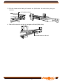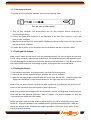
1
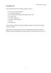
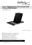
Kwik draw- B Series 1U 19” RACK MOUNTABLE LCD/Keyboard Drawer with KVM USER MANUAL Issue A DISCLAIMER This instruction manual is supplied to provide the user with sufficient information to utilise the purchased product in a proper and efficient manner. The information contained has been reviewed and is believed to be accurate and reliable, however Amplicon Liveline Limited accepts no responsibility for any problems caused by errors and omissions. Specifications and instructions are subject to change without notice. PACKING LIST Complete Kwikdraw-B 151/171/191 package consists of: z One 1U 19” rackmount console z Two cabinet mounting kits z One 1.8M cable( PS/2 mouse, PS/2 keyboard, DB15 VGA) z One power cord z One user manual CD z A pair of keys z Six flat screws Check to make sure that the unit was not damaged during shipping. Please read this manual thoroughly and follow the installation and operation procedures carefully to prevent any damage to the product, and/or any of the devices connected to it. SAFETY INSTRUCTIONS 1. Please read these safety instructions carefully. 2. Please keep this User Manual for later reference. 3. Please disconnect this equipment from AC outlet before cleaning. Do not use liquid or sprayed detergent for cleaning. Use moist sheet or cloth for cleaning. 4. For pluggable equipment, the socket-outlet should be installed near the equipment and should be easily accessible. 5. Please keep this equipment away from humidity. 6. Lay this equipment on a reliable surface before installation. A drop or fall could cause injury. 7. Do not leave this equipment in an environment with temperature above 600C, since it may damage the equipment. 8. The opening on the enclosure is for air flow to keep the equipment from overheating. DO NOT COVER THE OPENING. 9. Please keep the power cord tied up in such a way to keep people from stepping or tripping on it. Do not place anything on top of power cord. The power cord must be rated for the voltage and current marked on the product’s electrical ratings label. The voltage and current rating of the cord should be greater than the voltage and the current rating marked on the product. 10. Pay attention to all cautions and warnings listed in this manual. 11. If the equipment is not in use for long time, disconnect the equipment from mains to avoid being damaged by transient over-voltage. 12. Never pour any liquid into ventilation openings; this could cause fire or electrical shock. 13. Never open the equipment. For safety reasons the equipment can only be opened by qualified service personnel. 14. If one of the following situations arises, get the equipment checked by service personnel. z The power cord or plug is damaged. z The equipment has been exposed to moisture. z The equipment does not work well or you can not get it work according to User Manual. z The equipment has dropped and damaged. z If the equipment has obvious sign of breakage. 2 INDEX OF CONTENTS PACKING LIST ................................................................................................ 1 SAFETY INSTRUCTIONS .................................................................................... 2 INDEX OF CONTENTS ........................................................................................ 3 CHAPTER 1 GENERAL INFORMATION .................................................................... 5 1.1 Overview...............................................................................................5 1.2 Product Specification ................................................................................6 1.2.1 Kwikdraw-B 151 Specifications ............................................................6 1.2.2 Kwikdraw-B 171 Specifications ............................................................8 1.2.3 Kwikdraw-B 191 Specifications.............................................................10 CHAPTER 2 PANEL CONTROLS AND OSD FUNCTIONS ................................................ 12 2.1 Auto tune ......................................................................................... 12 2.2 Input Source ....................................................................................... 12 2.3 Brightness.......................................................................................... 13 2.4 Contrast............................................................................................ 13 2.5 Color................................................................................................ 13 2.6 Position ............................................................................................ 13 2.7 Language........................................................................................... 15 2.8 Recall............................................................................................... 15 2.9 Exit ................................................................................................. 16 2.10 Power Indicator ................................................................................... 16 CHAPTER 3 HARDWARE INSTALLATION ................................................................. 17 3.1 Install Console to Cabinet......................................................................... 17 3.1.1 Notes ............................................................................................ 17 3.1.2 Hardware Kits Contents ...................................................................... 17 3.1.3 Installation Step ............................................................................... 17 3.1.4 Replace Longer Bracket Step................................................................ 19 3.1.5 Unload Step .................................................................................... 20 3.2 Installing the Video Card and Video Driver..................................................... 22 3.2.1 Configuring the Display Settings .......................................................... 22 3.2.2 Connecting the Drawer ................................................................... 23 3.3 Turning on the Drawer ............................................................................ 23 3.4 Testing the Drawer ................................................................................ 23 CHAPTER 4 KVM SWITCH .................................................................................. 24 4.1 Introduction......................................................................................... 24 4.2 Features ............................................................................................. 24 4.3 Technical Specifications .......................................................................... 25 4.4 System Requirements ............................................................................. 25 4.5 Cable Diagram ...................................................................................... 25 3 4.6 Product Details ..................................................................................... 26 4.7 Hardware Installation ............................................................................. 26 4.8 Usage ................................................................................................ 27 4.9 Daisy Chain Connection Diagram ................................................................ 30 4.10 HotPlug............................................................................................. 31 4.11 OnScreenDisplay Operations .................................................................... 32 4.12 Trouble Shooting ................................................................................. 35 4 CHAPTER 1 GENERAL INFORMATION 1.1 Overview The Kwikdraw-B Series KVM Console is an ideal solution for multiple servers / platforms administration. Its 15-inch/17-inch/19-inch large size TFT LCD color display and ultra-low-profile compact industrial keyboard / touchpad provide the user-friendliest and most reliable environment for network administrators. All these functions are integrated in a 19-inch 1U space with rugged construction design to achieve ultra space saving and high reliability for high quality industrial network applications. The Kwikdraw-B Series KVM Console drawer provides superior picture quality and state-of-the-art features mounted in an industrial grade, rack mount drawer. The drawer forms a rugged enclosure that protects the monitor from industrial hazards and permits easy access to monitor controls. The Kwikdraw-B Series KVM Console monitor provides flicker-free color images at optimal resolutions. The monitor’s 0.264mm pixel pitch ensures crisp images with clear definition, even at high resolutions. The Kwikdraw-B Series KVM Console monitor is intelligent, microprocessor-based, and have an ergonomically designed display. The Kwikdraw-B Series KVM Console monitor employs the latest in active matrix thin film transistor (TFT) technology, providing crisp screen images and wide viewing angles. Unlike CRT monitors, LCD monitors are inherently immune to the magnetic fields commonly found on the plant floor or communications centers. LCDs are also typically brighter than conventional CRT technology, making them ideal for the high ambient lighting conditions found in many of today's factory environments. On-screen menus allow for display adjustments. In addition, the monitors' Plug-n-Play+ features support Windows 95/98,NT and XP, while a universal power supply ensures global applicability. The Kwikdraw-B Series KVM Console monitors are compatible with most analog RGB (red, green, blue) display standards, including PS/2, optional for Sun Micro System, Apple Macintosh Centris, Quadra, and Macintosh II family signals. The LCD monitor is capable of displaying crisp and vibrant color graphics with VGA, S2GA, XGA (non-interlaced), and most Macintosh compatible color video cards. 5 1.2 Product Specifications 1.2.1 Kwikdraw-B 151 Specifications Display Size 15" Panel Type Active Matrix TFT LCD Resolution Capabilities Maximum Resolution up to 1024X768 (XGA) Pixel Pitch Supports 0.297mm x0.297mm Viewing Angle (CR>10) Right-Left view 130 (Typ) Up-Down View 100 (Typ) Contrast Ratio 400:1 Brightness White 250cd/m2 (Center 1 point Typ) Back Light Dual Lamps for Back Light Supported Colors 16M Colors (6-bit with FRC) Response Time Rising Time 5ms, Decay Time 11ms Operating System Dos, Windows (3.1, 9x, 2000, NT4, ME, XP, 2003 Server) Linux, Novell 3.12-6, HP UX, SUN Multi Platform Support PS/2, SUN and USB System Cables VGA+2xPS/2 cable Keyboard Mouse 106 key PS/2 keyboard with touch pad Sync 45~80KHZ Power Source 100-240 VAC input Power Consumption 16W, 10.41W for Panel Temperature Operate 0°~ 50° C / 32° ~ 122°F Storage-20° ~ 60° C / -4° ~ 140°F Humidity 10%~90%RH Dimension 447.5x482x44mm / 17.6x19.0x1.7in Package Dimension 565x660x210mm / 22.2x26.0x8.3in Net Weight 11.8Kg / 26.0Lb Gross Weight 15.8Kg / 34.8Lb Chassis Construction Heavy duty steel materials Keyboard Language USA, UK, German, French, Spanish, Italian, Portuguese, Dutch, Swiss. Belgium, Swedish, Norwegian, Danish, Japan, Taiwan. Certification CE/FCC UL 6 7 1.2.2 Kwikdraw-B 171 Specifications Display Size 17" Panel Type Active Matrix TFT LCD Resolution Capabilities Maximum Resolution up to 1280X1024 (SXGA) Pixel Pitch Supports 0.264mm x0.264mm Viewing Angle (CR>10) Right-Left view 60~70 (Typ) Up-Down View 45~ 60(Typ) Contrast Ratio 450:1 Brightness White 250cd/m2 (Center 1 point Typ) Back Light Four Lamps for Back Light Supported Colors 16.2M Colors (6-bit with FRC) Response Time Rising Time 2ms, Decay Time 14ms Operating System Dos, Windows (3.1, 9x, 2000, NT4, ME, XP, 2003 Server) Linux, Novell 3.12-6, HP UX, SUN Multi Platform Support PS/2, SUN and USB System Cables VGA+2xPS/2 cable Keyboard Mouse 106 key PS/2 keyboard with touch pad Sync 45~80KHZ Power Source 100-240 VAC input Power Consumption 25W, 19.05W for Panel Temperature Operate 0°~ 50° C / 32° ~ 122°F Storage-20° ~ 60° C / -4° ~ 140°F Humidity 10%~90%RH Dimension 447.5x482x44mm / 17.6x19.0x1.7in Package Dimension 565x660x210mm / 22.2x26.0x8.3in Net Weight 13.0Kg / 28.66Lb Gross Weight 17.0Kg / 37.47Lb Chassis Construction Heavy duty steel materials Keyboard Language USA, UK, German, French, Spanish, Italian, Portuguese, Dutch, Swiss. Belgium, Swedish, Norwegian, Danish, Japan, Taiwan Certification CE/FCC UL 8 9 1.2.3 Kwikdraw-B 191 Specifications Display Size 19" Panel Type Active Matrix TFT LCD Resolution Capabilities Maximum Resolution up to 1280X1024 (SXGA) Pixel Pitch Supports 0.098mm x0.294mm Viewing Angle (CR>10) Right-Left view 140 (Typ) Up-Down View 140(Typ) Contrast Ratio 500:1 Brightness White 250cd/m2 (Center 1 point Typ) Back Light Four Lamps for Back Light Supported Colors 16.2M Colors (6-bit with FRC) Response Time Rising Time 2ms, Decay Time 10ms Operating System Dos, Windows (3.1, 9x, 2000, NT4, ME, XP, 2003 Server) Linux, Novell 3.12-6, HP UX, SUN Multi Platform Support PS/2, SUN and USB System Cables VGA+2xPS/2 cable Keyboard Mouse 106 key PS/2 keyboard with touch pad Sync 45~80KHZ Power Source 100-240 VAC input Power Consumption 25W, 21.05W for Panel Temperature Operate 0°~ 50° C / 32° ~ 122°F Storage-20° ~ 60° C / -4° ~ 140°F Humidity 10%~90%RH Dimension 447.5x532x44mm / 17.6x20.9x1.7in Package Dimension 565x660x210mm / 22.2x26.0x8.3in Net Weight 15.0Kg / 33.06Lb Gross Weight 19.0Kg / 41.88Lb Chassis Construction Heavy duty steel materials Keyboard Language USA, UK, German, French, Spanish, Italian, Portuguese, Dutch, Swiss. Belgium, Swedish, Norwegian, Danish, Japan, Taiwan Certification CE/FCC UL 10 11 CHAPTER 2 PANEL CONTROLS AND OSD FUNCTIONS Controls Description Soft power on/off button. Adjacent LED is lit when on. Auto Auto-synchronize and scale down display to any valid factory preset timings. Up Press to scroll the function you want to adjust. Down Press to scroll the function you want to adjust. Menu To access the main menu. This bottom also acts as the “Enter” bottom. 2.1 Auto tune Press the “Auto” button. The panel will adjust the display size automatically and also tunes itself to its best display condition. 2.2 Input Source 1. Press “Menu” button. 2. Use “Up” and “Down” button to highlight ‘Input Source’. Auto tune. Input Source Brightness Contrast Color Position Language Recall Exit 3. Press “Menu” button again to access the selection and you will see: VGA/DVI 4. Use “Up” and “Down” button to select the input source of signal. 5. Press “Menu” button to confirm selection. 12 2.3 Brightness 1. Press “Menu” button. 2. Use “Up” and “Down” button to highlight ‘Brightness’. Auto tune. Input Source Brightness Contrast Color Position Language Recall Exit 3. Press “Menu” button again to access the selection. 4. Use “Up” and “Down” button to adjust the desired brightness of the display. 5. Press “Menu” button to confirm selection. 2.4 Contrast 1. Press “Menu” button. 2. Use “Up” and “Down” button to highlight ‘Contrast’. Auto tune. Input Source Brightness Contrast Color Position Language Recall Exit 3. Press “Menu” button again to access the selection. 4. Use “Up” and “Down” button to adjust the desired contrast of the display. 5. Press “Menu” button to confirm selection. 2.5 Color Quality 1. Press “Menu” button. 2. Use “Up” and “Down” button to highlight ‘Color’. Auto tune. Input Source Brightness Contrast Color 13 Position Language Recall Exit 3. Press “Menu” button again to access the selection and you will see: Icon Description 9300°K To set CIE coordinates at 9300°K color 7500°K To set CIE coordinates at 7500°K color 6500°K To set CIE coordinates at 6500°K color User To set user defined CIE Auto color To auto adjust color Return To exit and return to the previous page 4. Use “Up” and “Down” button to select the desired color quality of the display. 5. Press “Menu” button to confirm selection. 2.6 Position 1. Press “Menu” button. 2. Use “Up” and “Down” button to highlight ‘Position’. Auto tune. Input Source Brightness Contrast Color Position Language Recall Exit 3. Press “Menu” button again to access the selection and you will see: Icon Description Image Pos To adjust the position of the image. OSD Pos To adjust the position of the OSD. Return To exit and return to the previous page 4. Use “Up” and “Down” button to select the desired position of the image or OSD display. 5. Press “Menu” button to confirm selection. 14 2.7 Language 1. Press “Menu” button. 2. Use “Up” and “Down” button to highlight ‘Language’. Auto tune. Input Source Brightness Contrast Color Position Language Recall Exit 3. Press “Menu” button again to access the selection and you will see: English German French Italian Spanish 4. Use “Up” and “Down” button to select the desired language of the OSD display 5. Press “Menu” button to confirm selection. 2.8 Recall 1. Press “Menu” button. 2. Use “Up” and “Down” button to highlight ‘Recall’. Auto tune. Input Source Brightness Contrast Color Position Language Recall Exit 3. Press “Menu” button again to access the selection and you will see: Yes/ No 4. Select “Yes” button then ‘Menu” to recover the factory setting or select “No “ to return to the previous page. 15 2.9 Exit Press “Exit” button to quit OSD menu. 2.10 Power Indicator GREEN ON RED STANDBY RED SUSPEND RED OFF Note: OSD – On Screen Display 16 CHAPTER 3 HARDWARE INSTALLATION 3.1 To Install Console to Cabinet 3.1.1 Notes 1. Please check all peripherals according the list before installation to make sure the unit was not damaged or the accessories were lost during shipping process. If you encounter any problem, please contact your dealer. 2. Before installation, make sure all peripherals and computers have been turned off. 3. The standard brackets are for 504~1000mm (distance between front bracket and rear bracket) cabinet, contact your dealer if you need brackets for deeper cabinet. VERY IMPORTANT CAUTION Kwikdraw-B Series consoles consist of 2 separable parts connected by an arm. During transportation, these parts are attached together by 4 gold color buttons. Please make sure that before and during installation, the console is held in HORIZONTAL position. Holding it in other than horizontal position will risk the parts to be detached from each other. The impact between any of the detached part with the floor or any hard object may cause the damage to the unit which is not the responsibility of Amplicon. 3.1.2 Hardware Kits Contents 1. Rail with front and rear bracket x 2. (Please identify the brackets. Right and left sides are different. For rack depth 504~828mm) 2. Long bracket x 2. (Needed for rack depth 828~1000mm) 3. Flat screw x 6 (To fix rails to console body) 17 4. Screw x 6 5. Key x 2 3.1.3 Installation Step 1. Loosen (Not release) four rear screws then adjust rear bracket to fit your cabinet. 2. Install front and rear bracket on cabinet. 3. Tight-up four rear screws. 4. Repeat step 1~3 for the other side. 18 5. Push console into left and right rails. 6. Unlock and pull rail–lock switch (left and right at the same time) then push console to the end. 7. Install and tighten three screws at the rear of the console. (Both sides) rail-lock switch 8. Finish installation as below. 3.1.4 Replace longer bracket Step (For rack depth 828~1000mm) 1. Release six screws. 19 2. Take rear bracket out. Original bracket 3. Input rear long bracket to rear of the rail then adjust rear bracket to fit your cabinet. Tighten-up 2~3 screws at the length you need. Leave the last one unscrewed. Rear long bracket 4. Repeat step 1~3 for the other side. 5. Repeat 3.1.3 step to install console to cabinet. 3.1.5 Unload Step 1. Make sure the console is locked. 2. Release three screws at the rear of the console. (Both sides) 3. Unlock. 4. Pull console out until console lock. 20 5. Pull rail-release switch and pull console out.(Both sides. Be careful when pulling out console.) rail-release switch 6. Push rail-lock switch on the rail and push rail back.(Both sides) rail-lock switch on the rail 21 3.2 Installing the Video Card and Video Driver Before connecting the LCD console, make sure your computer has a video card already installed for the monitor. After you connect the drawer, install the video software driver. The video driver is supplied by the video card manufacturer and may be found on the CDROM that came with your computer. If you need information to install a video card or video driver, refer to the manual that came with your video card. 3.2.1 Configuring the Display Settings After connecting the drawer and turning on your computer, you may need to configure one or more of the following display settings: z Display mode (also called desktop area or video resolution) z Refresh rate (also called vertical scan rate or vertical sync) z Color depth (also called color palette or number of colors) Each video card has several controls that let you adjust the display settings. However, the software and driver for each video card is unique. In most cases, you adjust these settings by using a program or utility provided by the manufacturer of the video card. Most video cards use the Windows Display Properties control panel to configure the display. To open the Windows Display Properties, click the right mouse button in a blank area of the Windows desktop and then select Properties. The Settings tab usually lets you change the Color Palette and the Desktop Area (x by y pixel resolution). Some video cards integrate additional features into the Windows Display Properties control panel to give you an exceptional setup that is flexible and easy to use. For example, the control panel may include an Advanced Properties button, an Adjustment tab, or a Refresh tab for changing other settings. Other video cards have a separate utility for setting display properties. Whenever you change the resolution, color, or refresh rate, the image size, position, or shape may change. This behavior is normal. You can readjust the image using the monitor on-screen controls. For more information on the monitor on-screen controls, refer to Chapter 2. For more information on configuring the display settings, refer to the manual that came with your video card. 22 3.2.2 Connecting the Drawer To connect an LCD console to a computer, perform the following steps AC INPUT DVI VGA USB MOUSE 100~240VAC 50~60Hz KEYBOARD The rear view of LCD console 1. Turn off your computer. You should always turn off your computer before connecting or disconnecting a device. 2. Connect the video (VGA) connector of the KVM cable to the video card connector on the rear panel of your computer. 3. Identify and connect the PS/2 mouse and PS/2 keyboard connector to the correct PS/2 ports on the rear panel of your computer. 4. Connect the AC power cord to the power inlet on the drawer and then to a power outlet. 3.3 Turning on the Drawer Make sure all cables and the power cord are connected properly. Be sure to tighten all connector screws. Using two hands, grasp the rear of the drawer, lift the tab and pull the panel up and forward. This will disengage the momentary on/off switch and the unit should power on. The LED on the left of the monitor panel should turn from orange to green, verifying that the unit is operational. 3.4 Testing the Drawer To test whether the drawer is working properly, perform the following steps: 1. Power up the monitor/keyboard drawer, and then turn on your computer. 2. Make sure the video image is centered within the screen area. Use the OSD controls to adjust the image (see note below) or press the Auto button on the right hand side of the monitor. Note: If the unit does not power up when the panel is pulled up, try pushing the soft power on/off button on the left side of the monitor panel to power up the unit. Note: You can adjust the horizontal and vertical position, contrast, and brightness to better suit your video card and your personal preference. Refer to Chapter 2 for more information on using the on-screen menu to adjust the video display Before you begin, make sure that powers to all the devices you will be connecting up have been turned off. To prevent damage to your installation due to ground potential difference, make sure that all the devices on the installation are properly grounded. Consult your direct vendor for any technical issues if necessary. 23 CHAPTER 4 KVM SWITCH 4.1 Introduction Controlling multiple computers from One Keyboard, Mouse and VGA Monitor. Rackmount Console is loaded with features such as 19” rackmount size, Daisy Chain up to Eight units, On Screen Display Menu, Password security, Searching PC server name, Hotkey Control (Include Auto Scan Control function). It has complete keyboard and mouse emulation for simultaneous PCs boot-up process. 4.2 Features z With 8/16 port PS/2 KVM switch inside of 19” rack mount size design z Support Microsoft Intellimouse, Microsoft Intellimouse Explorer, Logitech Net Mouse or the other fully compatible MS mouse. z Support Win98/98SE/ME/2000/XP, WinNT, HP Unix, Linux, Sun Solaris, MAC O.S 8.6 or later version z Manage multiple PCs, G3/G4 MACs, iMACs, SUN Microsystems with USB port from one USB keyboard, USB Mouse and Monitor. z Hot Plug - Add PCs or Remove Connected PCs for Maintenance without Powering Down the KVM switch or PCs. z Very High Video Quality - Up To 1920X1440, Bandwidth: 200MHz z Support eight characters password protection and search PC server name z Scan Intervals Mode for monitoring PCs and flexible Scan time from 5~99 seconds z Keyboard status restored when switching PCs z Buzzer sound for switching port confirmation. z Built-in one extra daisy chain port and no waste any PC port 24 4.3 Technical Specifications Model No. 8 port Rackmount USB KVM 16 port Rackmount USB KVM Switch Switch 8 16 VGA HDDB 15pin ( shared with USB port ) PC Port PC Port Connector (All Female Types) Daisy Chain Port Connector (All Female Types) On Screen Display Control 1 x VGA HDDB 15pin and 2 x Mini Din 6Pin special cable (3 to 3 cable) Yes Scan Intervals Keyboard Emulation Mouse Emulation VGA Resolution Bandwidth Daisy Chain MAX Level 5~99 Sec. PS/2 PS/2 1920X1440 200MHz 8 levels 4.4 System Requirements Model No. Computer side 8 port Rackmount Console 8 HDDB 15 pin male to one HDDB 15 pin male and Mini Din 6 pin special cables Model No. Computer side 16 port Rackmount Console 16 HDDB 15 pin male to one HDDB 15 pin male and Mini Din 6 pin special cables 4.5 Cable Diagrams PC Port Special Cable: HDB15 pin male to one HDDB 15 Pin male and Mini Din 6 Pin special cables 25 Daisy Chain Cable: PS/2 Cable: Mini Din 6 pin Male to Male VGA Cable: HDB 15 pin Male to Male 4.6 Product Details Rear Panel of 8 port Rackmount KVM Console: Rear Panel of 16 port Rackmount KVM Console: 4.7 Hardware Installation Before installation, please make sure all of peripherals and computers have been turned off. This example of installation is based on 8 port console and the 1 port or 16 port console have the same installation procedures Step 1: Each PC port connector is HDDB-15 pin type. Locate your input cable (It has a HDDB-15 Pin male connector at one end). Plug it into any computer port on the rear of console unit. The other end of input cable will have three connector; a HDDB-15 pin male type for PC video, a Mini Din 6 pin female type for keyboard and Mini Din 6 pin female type for mouse. Connect these three 26 connectors into the respective ports of computer. Repeat the same procedure to all of PCs. The rear side of PC Step 2: Double-check all of the connections. You can check the color of keyboard and mouse connector to make sure the keyboard and mouse cables go to the correct ports. Step 3: Attach the power supply to the Console unit and plug the other end into an electrical receptacle. Now you will see the LED for connected port light up, and you will hear a beep. Switch on your monitor. Note: Please be reminded to plug in power adapter. Although the PCs connected to KVM Switch are able to support enough power to the stand alone switch, KVM Switch still needs power to daisy chain more banks. 4.8 Usage The power on state of 8/16 port KVM switch: When you power on KVM switch, it will ask you the password, the default password value is eight zero –“ 00000000 “. Please key in eight zero and enter the same value at retype field. Note: Before you are familiar with the operation of OSD menu, you are strongly recommended not to change the password but keep the default eight zero (00000000) value instead, in case you forget the newly set password. 27 Keyboard HotKey Commands: You can also conveniently command Console by switching ports through simple key sequences. To send commands to Console, the “SCROLL LOCK” key must be pressed twice within 2 seconds. You will hear a beep for confirmation and the keyboard is in hotkey mode. If you have not pressed any key in hotkey mode within 2 seconds (It means to key in any key follows up “Scroll Lock” “Scroll Lock” key ), the keyboard will back to under Operation System control state. Below are the different hotkey commands: within 2 seconds Scroll Lock + Scroll Lock + ↑ = Previous Power On Channel (PC is Power On) Scroll Lock + Scroll Lock + ↓ = Next Power On Channel (PC is Power On) (Note: You also could press “up arrow key” or “down arrow key” longer time to speed up selecting the destination port) Scroll Lock + Scroll Lock + Page Up = Previous Bank (PC is power on) Scroll Lock + Scroll Lock + Page Down = Next Bank (PC is power on) 28 To select PC port: Scroll Lock Scroll Lock + Scroll Lock + Bank 1~8 + Scroll Lock + B Port No. 1~8 (8 port) 1~16 (16 port) Port No 0 or 1 = Beeper (Note: The default Beeper function is ON and beeper control is only for available for Scan Mode ) Scroll Lock + Scroll Lock S + = Auto Scan (Note: This function is just for power on PC PORT ) To get out of Auto Scan Mode, Press any key or SPACE bar. Scroll Lock + Scroll Lock R + OSD setting back to factory default value = (Note: Not including password) ROM Scroll Lock + Scroll Lock F + REFLASH Search the same PC name = (Note: Search PC name starting from 1st PC port) FIND: Scroll Lock + Scroll Lock Space Bar + = On Screen Display Menu Example: A. To access a computer attached to Port 4 of the console with hotkey: Scroll lock + Scroll lock + 1 + 04 B. To access a computer attached from Bank 3 to Bank 4, You can press through hotkey as 29 below: Scroll lock + Scroll lock + Page Down Note: Bank no. and Port no. selection must be made using the numeric keys on the keyboard. Numeric keys on the keypad are not available as a hotkey command 4.9 Daisy Chain Connection Diagram Please use the provided 1.8m 3-in-one daisy chain Cable Kit to daisy chain the KVM Switch. A. Use one end of 3-in-one Cable Kit to connect the daisy chain port on the Console and the other end for the console port (silver color block) of bank 2 KVM switch. B. Please repeat item A to daisy chain more bank as you want. But, the maximum daisy chain bank is eight levels. (Note: If you would like to daisy chain 8 port and 16 port PS/2 or USB KVM Switch together, the master bank must be 16 port PS/2 or USB Console.) LCD console Bank1 KVM switch Bank2 KVM switch Bank3 . . . . KVM switch Bank8 Maximum 8 Levels 30 4.10 Hot Plug The Console supports “Hot Plug“ function for easy addition or removal of PCs. The user can arrange or maintain PCs as follows: a. A PC can be disconnected and reconnected to the same or different port of the KVM unit without having to power it off as long as it is not the Daisy-chain port or pass through port. b. The pass through port PC (i.e. The pass through port means the console port is connected to PC directly) is powered on. Before you go hot plug function, please switch to this pass through port to next port (or say emulation port) and then switch back to the pass through port. c. You may unplug the mouse or the keyboard from the console port and plug it back in at any time. Note: Some O.S. (Operation Systems) like SCOUnix are unable to support “ Hot Plug ” function. If you apply “Hot Plug” to this kind of O.S., it will cause unpredictable behavior or shut down of the PC. Before attempting to use “Hot Plug” , please make sure your O.S. and mouse software driver supports the “Hot Plug” function. 31 4.11 On Screen Display Operation 1. OSD menu can be popped up in powered on PC port or non-powered on PC port or empty PC port. The resolution of OSD menu is fixed to 1024X768 for non-powered on PC port or empty PC port. 2. When you pop up the OSD menu window through the hotkey, you will see the following small window on your monitor. BANK : 1 01 SYSTEM 01 02 ☼SYSTEM 02 03 ☼SYSTEM 03 04 ☼SYSTEM 04 05 ☼SYSTEM 05 06 SYSTEM 06 07 SYSTEM 07 08 ☼SYSTEM 08 09 SYSTEM 09 10 SYSTEM 10 11 ☼SYSTEM 11 12 ☼SYSTEM 12 13 SYSTEM 13 14 ☼SYSTEM 14 15 ☼SYSTEM 15 16 SYSTEM 16 OSD : 10 SEC. SCAN : 10 SEC. CHANGE PASSWORD CONSOLE ON/OFF ESC : QUIT ENTER : COMPLETE TAB : NEXT INSERT : EDIT © / ª : PORT SELECT PgDn/PgUp : BANK SELECT a. b. The 1 st line bar is Bank no. st The 2 block is your PC system name list. You will find the system number list from 01 to 04 (if the current box is 4 ports) or from 01 to 8 (if the current box no. is 8 ports) or from 01 to 16 (if the current box no. is 16 ports). You can define your PC name in maximum 8 characters. The factory default of 16 port Console PC name is from “SYSTEM 01”, SYSTEM 02”,…,”SYSTEM 16” and 8 port Console is from “SYSTEM 01”, “SYSTEM 02”,…,”SYSTEM 08”. Besides, the sun symbol “☼“near to the PC system is powered on. Use arrow key “©” or down arrow key “ª” to select port for destination PC name, press ENTER key after you highlight the selected PC port. 32 Use “ PgUp” key or “PgDn” key to select previous or next Bank no.(or Box No.) BANK : 1 01 SYSTEM 01 02 ☼SYSTEM 02 Press “INS” key to edit PC name and press “ENTER” key for saving information. To use “TAB” key to select items like Bank, OSD, SCAN, CHANGE PASSWORD, CONSOLE ON /OFF, etc… 15 ☼SYSTEM 15 OSD : 10 SEC. SCAN : 10 SEC. 16 SYSTEM 16 CHANGE PASSWORD CONSOLE ON/OFF ESC : QUIT ENTER : COMPLETE TAB : NEXT INSERT : EDIT 甲、 The “OSD: 10 SEC” means the OSD shows as long as 10 sec on your display. You can modify it from 05 sec to 99 sec. The factory default value is 10 sec… 乙、 The “SCANTIME” is the scan interval from one PC port to next PC port. The default SCAN time is 10 sec and the maximum scan time is 99 sec. 丙、 The “CHANGE PASSWORD” function can be used to avoid unauthorized personnel to access any computer connected. The default password is 8 digits “00000000 “. ENTER ESC : QUIT PASSWORD : ENTER : COMPLETE There is an ‘Enter Password’ window pop-up when you select this item. Type in the password then press ‘Enter’ key to confirm. The maximum password is eight digits. After you key in the password already and press the Enter key, there is another window for confirming your typed password. ENTER NEW ESC : QUIT RETYPE NEW ESC : QUIT PASSWORD : ENTER : COMPLETE PASSWORD : ENTER 33 33 : COMPLETE You need to retype the password to check whether the previous keyed-in password is matched or not. NEW PASSWORD ESC : QUIT COMPLETE ENTER : COMPLETE 丁、 “CONSOLE ON/OFF“ manages the accessibility to the console. “CONSOLE ON “ means any user can use the console. “CONSOLE OFF “(factory default OFF state) means only user authorized with password is allowed to use the console. After the correct password is entered and passed KVM switch authentication, the CONSOLE will be set to ON. After you finish using KVM switch, please don’t forget to set up CONSOLE ON state to OFF state. if the CONSOLE is in ON state and you reset KVM switch, the CONSOLE will be set up back to OFF state. 戊、 When you finish setting up PC name and get out of OSD setting mode, you will find the PC name showed at the upper-left corner of the display. You can use ESC key to clear the message right away if you don’t need it. 102 ☼SYSTEM 02 己、 If you want OSD to return back to factory default value, you can execute “SCROLL LOCK”, “SCROLL LOCK”, “R” keys in order. The bank seven segments LED on the front panel will be flashed during the refresh process. ROM REFLASH When the OSD value back to default setting, the bank seven segments LED on the front panel will stop flashing. 34 4.12 Troubleshooting 1. Ensure that all cables are well seated. Label all of cables with the number for each respective computer to avoid confusion. 2. The recommended VGA cable distance is 5 meters maximum without ghosting and degradation. Normally, the cable length is based on driver capacity of your VGA card. If you need longer VGA cable, please use VGA extender to accomplish your applications. 3. The recommended PS/2 cable distance is 5 meters maximum. Normally, the cable length is based on driver capacity of your motherboard PS/2 port. If you need longer PS/2 cable, please use PS/2 extender to accomplish your applications. 4. Don’t press any keys on the keyboard while the selected computer is booting up. Otherwise, it might cause the keyboard error or keyboard is not detected at PC side. 5. The computer boot up fine, but keyboard doesn’t work z Make sure the keyboard works when directly plugged into the computer. z Try a different keyboard, but use only 101, 102 or 104-key keyboard. 6. The Mouse is not detected during PC boot up. z Make sure the mouse works when directly plugged into the computer z Make sure the mouse is a true PS/2 mouse. A combo mouse will work just as long as it is set for PS/2 mode with the correct adapter. Try a different mouse. z Avoiding moving the mouse or pressing the mouse buttons when switching ports. z Avoiding switching ports during shutting down the PC process. When you switch one PC port to another PC port, the best scan time setting needed to be set to 5 sec. or more. Normally, the VGA monitor change one resolution mode to another will take one or two seconds. So, the scan time is not recommended to be below 5seconds KwikDraw-B Series Manual Part No 85070156 Issue A 35