1
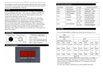
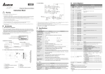
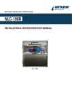
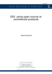
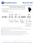
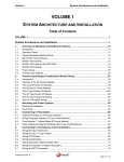
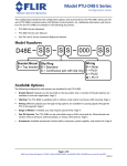
Last Updated: 15-March-2010 TB-020501C Technical Bulletin, Communicating with Daniel Ultrasonic Gas Flowmeter Model 3400, SeniorSonic OMNI FLOW COMPUTERS, INC. 12620 West Airport Boulevard, Suite 100 Sugar Land, Texas 77478 United States of America Phone-281.240.6161 Fax: 281.240.6162 www.omniflow.com 52-0004-0003/Rev C Page 1 of 18 TB-020501C Communicating with Daniel Ultrasonic Gas Flowmeter Model 3400, SeniorSonic NOTE: User Manual Reference - This Technical Bulletin complements the information contained in the User Manual, applicable to Revision 23.74/27.74+. The Daniel SeniorSonic ultrasonic flowmeter measures gas flow by using the Time Travel method of acoustic pulses. This service communicates with OMNI Flow Computers via OMNI’s ‘SV’ process I/O combo module using a proprietary protocol. To use the scaled pulse output of the Daniel Senior Sonic Metering, the flow computer must at least either have an ‘A”, ‘B’ or ‘E’ combo module installed. Table of Contents Scope ............................................................................................................................................3 Abstract .........................................................................................................................................3 SeniorSonic Ultrasonic Flowmeter Theory of Operation ...............................................................3 OMNI Flow Computer Logic ..........................................................................................................3 Modbus Communication................................................................................................................5 Wiring Installation ..........................................................................................................................5 OMNI Combo Module Terminal Assignments ...........................................................................5 SeniorSonic 3400 Terminal Assignments .................................................................................7 Other SeniorSonic 3400 Terminal Assignments .......................................................................7 Forward & Reverse Flow Signals ..............................................................................................9 Forward Flow Only with (Dual) Pulse Fidelity & Integrity Checking ........................................10 Forward & Reverse Flow with (Dual) Pulse Fidelity & Integrity Checking ...............................11 OMNI Flow Computer Configuration ...........................................................................................12 Miscellaneous Configuration Meter Run Settings ...................................................................12 Meter Run Setup Entries .........................................................................................................12 OMNI Flow Computer Database Addresses & Index Numbers ..................................................13 OMNI Flow Computer User Displays ..........................................................................................16 SV Module Serial Communications Port .................................................................................16 Meter Run Data .......................................................................................................................17 Figures Figure 1. Figure 2. Figure 3. Figure 4. Figure 5. Figure 6. Daniel SeniorSonic 3400 Ultrasonic Gas Flowmeter ....................................................4 Daniel Senior Sonic 3400..............................................................................................9 Daniel SeniorSonic 3400.............................................................................................10 Daniel SeniorSonic 3400.............................................................................................11 Display Mode ..............................................................................................................16 Meter Run Data Display Mode ....................................................................................17 52-0004-0003/Rev C Page 2 of 18 TB-020501C Communicating with Daniel Ultrasonic Gas Flowmeter Model 3400, SeniorSonic Scope This Technical Bulletin applies to firmware revisions 23.74+ and 27.74+ of OMNI 6000/OMNI 3000 Flow Computers, for gas flow metering systems. Abstract The Daniel SeniorSonic ultrasonic flowmeter determines the linear gas velocity through the meter tube by using multiple acoustic pulse paths. The flowmeter analyzes these paths employing the delta time travel measurement method. The OMNI Flow Computer either totalizes the flowmeter pulse input signal or determines the flowrate from the data received serial from the flowmeter. SeniorSonic Ultrasonic Flowmeter Theory of Operation Daniel's ultrasonic gas flow-metering technology incorporates multiple pairs of transducers into a smart digital inferential instrumentation device. This device is installed into a gas pipeline system to measure gas flow. Each pair of transducers emits ultrasonic (acoustic) pulses that travel bi-directionally, to and from each transducer in the pair. Four (4) pairs of transducers are positioned across the meter so that the path between each transducer has an axial component; i.e., one (1) transducer is upstream relative to the other. Pulses emitted by the downstream transducer are slowed down by the velocity of the fluid, with flow the pulse takes longer to travel to the upstream transducer than with no flow. Pulses emitted by the upstream transducer are aided by the velocity of the fluid, with flow the pulse takes less time to travel to the downstream transducer. Ultrasonic flowmeters such as the SeniorSonic 3400, that apply delta time methodology, measure these two travel times to determine both the linear fluid velocity and the speed of sound in the fluid. The flowmeter can measure fluid velocity for bi-directional (forward/reverse) fluid flow. OMNI Flow Computer Logic The OMNI Flow Computer can determine the actual flow rate from data received either serially from the SeniorSonic flowmeter, or from a live pulse frequency signal input if one has been connected, assigned, and configured. In this application, Modbus serial communication can be configured as the primary measurement source with the pulse frequency configured as the backup measurement source or vice versa to determine the actual flow rate. The OMNI Flow Computer can also be configured to use only the Modbus serial communication link with no pulse frequency input. When Modbus communications are available the flow computer transmits flowing temperature and pressure to the flowmeter to enable it to correct spool dimensions. The flowmeter serially transmits the accumulated volume to the OMNI. The flow computer obtains a calculated volume increment by subtracting the new accumulated volume from the last accumulated volume it received. The flowmeter updates its totalizers on a regular interval depending upon flowing conditions and configuration settings. Updating the OMNI totalizers on this same period would result in somewhat erratic totalizers and sampler pulse outputs, which could upset other equipment connected to the flow computer. The OMNI provides a smooth totalizer update by monitoring the time interval between SeniorSonic totalizer updates, and distributing the volume increment over a matching time-period (Figure 1). 52-0004-0003/Rev C Page 3 of 18 TB-020501C Communicating with Daniel Ultrasonic Gas Flowmeter Model 3400, SeniorSonic Start Are SV Serial Communications OK ? Set SeniorSonic Communication Failed Alarm No Yes Is Pulse I/O Assigned ? Clear SeniorSonic Communication Failed Alarm Yes No Is Transmitter Flowrate in Correct Direction ? Disable Totalizing No Yes Is Pulse I/O Assigned ? No Clear Pulse Signal Suspect Alarm Set Meter Run Not Active Yes Is SV Communications Primary ? No Calculate Flow Based on Pulses Yes Calculate Flow Based on SV Link Compare Flow Based on Pulses to Serial Data Flow Compare Flow Based on Pulses to Serial Data Flow No Is Flow Comparison within Limits ? No Set Pulse Signal Suspect Alarm Is Flow Comparison within Limits ? Yes Clear Pulse Signal Suspect Alarm Yes Clear Pulse Signal Suspect Alarm Totalize Flow Based on Pulse Input Signal Totalize Flow Based on Transmitted Serial Data End Figure 1. Daniel SeniorSonic 3400 Ultrasonic Gas Flowmeter In the event of a communication failure between the two (2) devices, the OMNI will not receive serial data. However, the SeniorSonic may be fully operational and continue to accumulate volume. In this case, if a pulse signal is available from the flowmeter and the OMNI Flow Computer is configured to receive the flow pulse signal as a backup, the flow computer will automatically continue to accumulate flow based on this flow pulse train. When normal communications resume, the flow computer will validate and adjust its internal totalizers if necessary to match the SeniorSonic internal totalizer. The flow computer automatically adjusts its totalizers to account for the small amount of flow that takes place before it detects that a communication failure has occurred (i.e., the OMNI does not immediately start totalizing using the SeniorSonic pulse train). If a pulse signal from the SeniorSonic is not available, and the communication link fails, the flow computer immediately stops totalizing. Once communication is reestablished, the OMNI will adjust its internal totalizers to match the SeniorSonic totalizer. In this case, the OMNI may have to add a significant amount of flow to its totalizers, depending upon how much time the communication link was inoperative. 52-0004-0003/Rev C Page 4 of 18 TB-020501C Communicating with Daniel Ultrasonic Gas Flowmeter Model 3400, SeniorSonic In some instances, adjusting the flow computer’s totalizers may not be desirable; e.g.: if a flowmeter has been disconnected for a long period of time, or the SeniorSonic electronics package has been replaced. For these cases, there are flow computer configuration settings that specify the maximum time that a SeniorSonic serial communication failure can exist, and still be compensated for by adjusting the flow computer totalizers. By default, this maximum time is fifteen (15) minutes. Modbus Communication NOTE: The serial interface between these devices is 2-wire RS-485 mode utilizing a modified Modbus protocol. The SeniorSonic connects to an external system using the Modbus ASCII protocol via a serial line. This connection is typically a 2-wire RS-485 serial link. Communications parameters are fixed in the OMNI (Table 1): Table 1. Fixed Communications Parameters Setting Value Baud Rate 9600 Data Bits 7 Stop Bits 1 Parity Even Protocol Modbus ASCII NOTE: In order to communicate with Daniel Senior Sonic ultrasonic flowmeters, the OMNI Flow Computer must be equipped with at least one (1) SV combo module (Model 68-6203). For instructions on jumper settings and other process I/O combination module setup information, refer to Volume 1, Chapter 2 of the OMNI User Manual. Wiring Installation There are several options for wiring a SeniorSonic ultrasonic meter to an OMNI Flow Computer. The option to implement depends upon requirements of the flow metering system. Always interconnect these devices via a 2-wire RS-485 serial interface from the SeniorSonic to an OMNI SV combo module serial port. This connection uses the Modbus protocol to transmit to the OMNI the volumetric flow data that the SeniorSonic accumulates. The OMNI also transmits the fluid temperature and pressure to the flowmeter to allow the flowmeter to correct for dimensional changes of the measurement Spool. In addition to serial data, the OMNI can also receive live forward and/or reverse flow pulse signals from the SeniorSonic. The SeniorSonic transmits pulse frequencies through wires typically connected to an OMNI E combo module. Connecting two (2) SeniorSonic pulse output channels to the OMNI can provide pulse fidelity and integrity checking. To perform pulse fidelity checking, the OMNI must have one (1) E combo module for each flow direction requiring totalization. OMNI Combo Module Terminal Assignments Depending upon the implemented wiring option, the OMNI requires SV, E, and/or A combo modules. Tables 2 thru 4 specify the terminal assignments for each module type. This information is necessary when connecting wires to the OMNI. The terminal block number (TBn) on the OMNI back panel for each combo module corresponds to the slot on the motherboard into which the module is plugged. For more information, refer to “Volume 1: System Architecture and Installation” of the OMNI User Manual. 52-0004-0003/Rev C Page 5 of 18 TB-020501C Communicating with Daniel Ultrasonic Gas Flowmeter Model 3400, SeniorSonic Table 2. OMNI SV Combo Module Back Panel Terminal Assignments (TBn) Terminal 1 2 3 4 5 6 7 8 9 10 11 12 Note: Signal Description Port # 1 (3): RS-485 B Wire Port # 1 (3): RS-485 A Wire Port # 2 (4): RS-485 B Wire Port # 2 (4): RS-485 A Wire Signal Return for 4-20mA Analog Outputs Signal Return for 4-20mA Analog Outputs Analog Output # 5: 4-20mA Analog Output # 6: 4-20mA Analog Output # 3: 4-20mA Analog Output # 4: 4-20mA Analog Output # 1: 4-20mA Analog Output # 2: 4-20mA Numbers in parenthesis “( )” refer to SV module 2 if installed. Table 3. OMNI E Combo Module Back Panel Terminal Assignments (TBn) Terminal 1 2 3 4 5 6 7 8 9 10 11 12 Signal Description Input Channel # 1: 1-5v, 4-20mA, RTD Input Channel # 1: Isolated Signal Return Input Channel # 2: 1-5v, 4-20mA, RTD Input Channel # 2: Isolated Signal Return Input Channel # 3: Flowmeter Pulses Input Channel # 4: Flowmeter Pulses Double Chronometry Detector Switch Input (Active Low) RTD Excitation Current Source Output #2 RTD Excitation Current Source Output #1 Signal Return for Terminals 5, 6, 7, 8, 9, 11 & 12 (Internally connected to DC power return Analog Output # 1: 4-20mA Analog Output # 2: 4-20mA Table 4. OMNI A Combo Module Back Panel Terminal Assignments (TBn) Terminal 1 2 3 4 5 6 7 8 9 10 11 12 Signal Description Input Channel # 1: 1-5v, 4-20mA, RTD Input Channel # 1: Isolated Signal Return Input Channel # 2: 1-5v, 4-20mA, RTD Input Channel # 2: Isolated Signal Return Input Channel # 3: Flowmeter Pulses Input Channel # 3: Isolated Signal Return Input Channel # 4: Flowmeter Pulses Input Channel # 4: Isolated Signal Return RTD Excitation Current Source Output #1 Signal Return for Terminals 9, 11 & 12 (Internally connected to DC power return Analog Output # 1: 4-20mA Analog Output # 2: 4-20mA or RTD Excitation Current Source Output #2 (See JP12 Setting) 52-0004-0003/Rev C Page 6 of 18 TB-020501C Communicating with Daniel Ultrasonic Gas Flowmeter Model 3400, SeniorSonic SeniorSonic 3400 Terminal Assignments Using the two (2) P2 terminal blocks # 3-3400-017 in the Senior Sonic to connect to the OMNI, Tables 5 and 6 specify the terminal assignments for each of these terminal blocks. This information is necessary when connecting wires to the Senior Sonic. NOTE: Users of this Meter Model MUST verify the revision level of the installed meter and refer to that revision’s Operations and Installation Manual supplied with the meter for the correct terminals required for meter frequency and serial wiring. The wiring terminals will vary for each revision level. Table 5. SeniorSonic 3400 Electronics Board Terminal Block P2 Assignments Board # 3-3400-017 Terminal 1 2 3 4 5 6 7 8 9 10 11 12 Signal Description DIG GND (Negative) DIG GND (Negative) FREQ1A Fwd Flow Pulses (Positive) FREQ1B Fwd Flow Fidelity Pulses (Positive) FREQ2A Rev Flow Pulses (Positive) FREQ2B Rev Flow Fidelity Pulses (Positive) N/A N/A N/A N/A N/A N/A Table 6. SeniorSonic Peripherals Terminal Block P2 Assignments Terminal 12 11 10 *9 *8 *7 Signal Description Signal Ground RS-485- (Negative) RS-485+ (Positive) Signal Ground RS-485- (Negative) RS-485+ (Positive) Note * 12, 11, and 10 are internally connected to 9, 8, and 7 Other SeniorSonic 3400 Terminal Assignments Tables 7 and 8 specify the terminal assignments for the terminal block # 2-3-3400-421. NOTE: Users of this Meter Model MUST verify the Revision level of the installed Meter and refer to that revision’s Operations and Installation Manual supplied with the meter, for the correct terminals required for meter frequency and serial wiring. The wiring terminals will vary for each revision level. 52-0004-0003/Rev C Page 7 of 18 TB-020501C Communicating with Daniel Ultrasonic Gas Flowmeter Model 3400, SeniorSonic Table 7 SeniorSonic 3400 Electronics Board Terminal Block J4 and J5 Assignments Board # 2-33400-421 Terminal J4-1 J4-2 J4-3 J4-4 J4-5 J4-6 J5-1 J5-2 J5-3 J5-4 J5-5 J5-6 Signal Description DOUT1B DOUT1A DOUT1A GND1 GND1 FOUT1B DOUT2B DOUT2A GND2 GND2 FOUT2B DOUT2A } } To Flow Computer To Flow Computer Table 8. SeniorSonic Peripherals Terminal Block J6 Port A or J7 Port B Assignments Terminal RS232 Signal Description RS485 1 RX RX + 2 3 4 TX COMM GND RTS RX COMM GND RTS 5 CTS CTS 52-0004-0003/Rev C Page 8 of 18 TB-020501C Communicating with Daniel Ultrasonic Gas Flowmeter Model 3400, SeniorSonic Forward & Reverse Flow Signals Figure 2 is a typical wiring installation between the Daniel SeniorSonic with P2 of the connection board # 3-3400-017 and an OMNI 6000 for serial data and both forward and reverse flow signals. Figure 2, assume that the OMNI 6000 has an A module plugged into slot TB5, and an SV module in slot TB6. DANIEL SENIOR SONIC ULTRASONIC FLOWMETER P2 Electronics Peripheral Field Connection Board DIG-GND 1 DIG-GND FREQ1A 2 3 FREQ1B 4 FREQ2A 5 FREQ2B 6 OMNI FLOW COMPUTER BACK PANEL TERMINAL BLOCKS A Combo Module Terminals (TB5) 1 2 (FWD) (REV) 3 Pulse In Return Pulse In 7 Return 4 5 6 7 8 3rd Input Channel 4th Input Channel 9 10 11 12 16 Electronics Terminal Board SV Combo Module Terminals (TB6) RS485C 12 RS-485- 11 1 RS-485 - (B) 2 RS-485 +(A) RS-485+ 10 3 RS-485 - (B) RS-485C 9 4 RS-485 +(A) 8 7 6 5 5 8 4 3 9 10 2 11 1 12 RS-485RS-485+ Port #1 Port #2 6 7 Figure 2. Daniel Senior Sonic 3400 Example of wiring a Daniel SeniorSonic 3400 ultrasonic flowmeter (Figure 2) to an OMNI 6000 Flow Computer with connections for serial data and live forward and reverse flow signals (without pulse fidelity and integrity checking). 52-0004-0003/Rev C Page 9 of 18 TB-020501C Communicating with Daniel Ultrasonic Gas Flowmeter Model 3400, SeniorSonic Forward Flow Only with (Dual) Pulse Fidelity & Integrity Checking Figure 3 is a typical wiring installation between the Daniel SeniorSonic with P2 of the connection board # 3-3400-017 and an OMNI 6000 for serial data and forward flow signals, with connections for pulse fidelity and integrity checking. In Figure 3, assume that the OMNI 6000 has an E module plugged into slot TB5, and an SV module in slot TB6. DANIEL SENIOR SONIC ULTRASONIC FLOWMETER P2 Electronics Peripheral Field Connection Board DIG-GND DIG-GND FREQ1A E Combo Module Terminals (TB5) 1 1 2 3 FREQ2A 4 5 FREQ2B 6 FREQ1B OMNI FLOW COMPUTER BACK PANEL TERMINAL BLOCKS 2 3 FWD (A) FWD (B) 4 Pulse In Pulse In 5 3rd Input Channel 6 4th Input Channel 7 8 7 Signal Return 9 10 11 16 12 Electronics Terminal Board SV Combo Module Terminals (TB6) RS-485C 12 RS-485- 11 10 RS-485+ RS-485C RS-485RS-485+ 1 RS-485- (B) 2 RS-485+(A) 3 RS-485- (B) Port#1 Port#2 4 RS-485+(A) 9 8 5 6 7 6 5 7 8 4 3 9 10 2 11 1 12 Figure 3. Daniel SeniorSonic 3400 Example of wiring a Daniel SeniorSonic 3400 ultrasonic flowmeter (Figure 3) to an OMNI 6000 Flow Computer with connections for serial data, live forward flow signal, and pulse fidelity and integrity checking. 52-0004-0003/Rev C Page 10 of 18 TB-020501C Communicating with Daniel Ultrasonic Gas Flowmeter Model 3400, SeniorSonic Forward & Reverse Flow with (Dual) Pulse Fidelity & Integrity Checking Figure 4 is a typical wiring installation between the SeniorSonic with P2 of the connection board # 3-3400017 and an OMNI 6000 for serial data and both forward and reverse flow signals, with connections for pulse fidelity and integrity checking. Figure 4 assumes that the OMNI 6000 has two (2) E modules in slots TB5 and TB6, and an SV module in slot TB7. DANIEL SENIOR SONIC ULTRASONIC FLOWMETER P2 Electronic Peripherial Field Connection Board DIG-GND DIG-GND FWD FREQ1A FREQ1B REV FREQ2A FREQ2B OMNI FLOW COMPUTER BACK PANEL TERMINAL BLOCKS E Combo Module Terminals (TB5) 1 2 1 2 3 4 3 4 Pulse In 5 6 Pulse In 7 8 5 3rd Input Channel 6 4th Input Channel 7 8 9 10 Signal Return 9 10 11 12 11 12 13 14 E Combo Module Terminals (TB6) 15 16 1 2 3 4 Pulse In Pulse In 5 3rd Input Channel 6 4th Input Channel 7 8 Signal Return 9 10 11 12 Electronics Termnial Board RS-485C RS-485RS-485+ RS-485C RS-485RS-485+ SV Combo Module Terminals (TB7) 12 11 1 RS-485- (B) 2 RS-485+(A) Port#1 10 9 3 RS-485- (B) 4 RS-485+(A) Port#2 8 7 6 5 5 6 4 3 9 10 2 1 11 12 7 8 Figure 4. Daniel SeniorSonic 3400 Example of wiring a Daniel SeniorSonic 3400 ultrasonic flowmeter (Figure 4) to an OMNI 6000 Flow Computer with connections for serial data, live forward reverse flow signals, pulse fidelity, and integrity checking. 52-0004-0003/Rev C Page 11 of 18 TB-020501C Communicating with Daniel Ultrasonic Gas Flowmeter Model 3400, SeniorSonic OMNI Flow Computer Configuration Use the flow computer’s front panel keypad to enter configuration settings unique to the SeniorSonic Flowmeter. The configuration settings that are specific to the SeniorSonic flowmeter are under Miscellaneous Setup, Configure Meter Run menu and the Meter Run Setup menu. Enter the miscellaneous configuration meter run settings first and then proceed to the meter run setup entries (Review Chapter 2 Flow Computer Configuration in Volume 3 of the OMNI User Manual, and the Technical Bulletin 960701 (52-0000-0001) Overview of OMNICOM Configuration PC Software). Miscellaneous Configuration Meter Run Settings The following miscellaneous configuration meter run settings correspond to the SeniorSonic ultrasonic gas flowmeter: Select Flowmeter Device Type – For each meter run, enter [8] to select the Daniel Ultrasonic flowmeter as the device type. Select SV Module Port – The OMNI Flow Computer can accept two (2) SV combo modules. With one (1) SV module, two (2) SV ports are available, and with two (2) SV modules, four (4) ports are available. For each ultrasonic meter run, enter the SV port number (1 to 4) to which the SV module’s RS-485 serial interface input from the SeniorSonic flowmeter is wired to the OMNI. DFI Address – This is the address ID of the Daniel ultrasonic flowmeter communications port. DFI Retry – This is the number of SV serial port communications retries the OMNI will attempt with the flowmeter after a communications failure before actually raising a communications fail alarm. Flow I/O Point – Enter the input channel number that is used to input the ultrasonic flowmeter pulse signal. Assign flowmeter pulse signals only to Input Channels #3 and #4 of A or E combo modules, or input channel #3 of a B combo module. Select Flow Direction (F/R) – SeniorSonic flowmeters allow for bi-directional fluid flow measurement. For pulse frequency signals, setup the flow computer to totalize either forward or reverse flow on any meter run with an ultrasonic flowmeter. Primary Flow – This setting instructs the OMNI Flow Computer to use either the pulse input channel or the SV serial communications data as the primary means of calculating flow. Options are: 0 = Select Serial Data as primary flow. This means that the SV serial communications data will be the primary and the pulse input channel, if assigned, will be used as a backup means of flow calculations by the flow computer. 1 = Select Pulse Input as primary flow. This means that the flow pulses received from the flowmeter will be the primary and the SV serial communications data will be used as a backup means of flow calculations by the flow computer. Meter Run Setup Entries NOTE: Difference Between ‘Gas Velocity’ and ‘Velocity of Sound’ – The ‘velocity of sound’ (VOS) refers to the amount of time it takes an acoustic pulse to travel along the gas ultrasonic paths. The VOS will vary depending upon gas type and line conditions The following meter run setup entries are available for the SeniorSonic ultrasonic flowmeter when using pulse frequency signals: Velocity of Sound (VOS) in Gas, Deviation Percent from Average – In some configurations, the flow computer can verify that the average VOS calculated for all paths conforms to the VOS of each individual path. This entry is the maximum percent that any one path VOS varies from the average VOS of all the paths. Flow Minutes – The time interval can be set for comparing the flow pulses input flow with the SV communications serial link flow. If the flow deviation exceeds the Flow Deviation Percent setting (see next setting) when this comparison is made, the OMNI will switch from the primary (flow pulses or SV serial link) to the backup source (SV serial link or flow pulses) for calculating flow. NOTE: Daniel Industries recommends a minimum of sixty (60) minutes for this setting due to the fluctuating flow pulse frequency output by the flowmeter. 52-0004-0003/Rev C Page 12 of 18 TB-020501C Communicating with Daniel Ultrasonic Gas Flowmeter Model 3400, SeniorSonic Maximum Flow Deviation Percent Only valid if a flow pulse’s I/O point is assigned. This is the allowable percent of deviation between the calculated flow from the pulse input channel compared to the SeniorSonic flow data received via the OMNI SV serial port. The OMNI raises the pulse suspect alarm if the flow deviation percentage exceeds this limit. NOTE: Refer to the Flow Minutes setting previous. Maximum Meter Downtime Enter the maximum allowable flowmeter downtime in minutes. If communication downtime between the OMNI and the SeniorSonic is greater than this value, the OMNI will not adjust its internal totalizers to match the most recent SeniorSonic totalizer value. Depending upon how much time the communication link and pulses were inoperative and the amount of flow that occurred during this downtime, when communications is reestablished within the time specified in this setting, the OMNI may have to add a significant amount of flow to its totalizers. (Default = 15) OMNI Flow Computer Database Addresses & Index Numbers Tables 9 thru 17 list the Modbus database addresses assigned within OMNI firmware to the SeniorSonic ultrasonic metering feature. These tables categorize data type. Table 9. Meter Run Alarm Status Points – Real Time Data Database Address Description Loss of communication For Meter Run Number 1 2 3 4 2154 2254 2354 2454 Loss of pulse input 2155 2255 2355 2455 Flow rate deviation alarm 2156 2256 2356 2456 Path 0 – Gas VOS alarm 2181 2281 2381 2481 Path 1 – Gas VOS alarm 2182 2282 2382 2482 Path 2 – Gas VOS alarm 2183 2283 2383 2483 Path 3 – Gas VOS alarm 2184 2284 2384 2484 Table 10. 16-Bit Integer Register – Real Time Data Description Database Address for Meter Run Number 1 Flow direction (0=frwd,1=rvrs) 3155 2 3 4 3255 3355 3455 Table 11. 32-Bit Integer Register – Real Time Data Description Database Address for Meter Run Number 1 2 3 4 Volume From UFM (FWD) 15530 15630 15730 15830 Volume From UFM (REV) 15532 15632 15732 15832 NOTE: Table 11 Modbus registors are available in 23.74.20 and later, 23.75.00 and later, 27.74.19 and later, and 27.75.00 and later. 52-0004-0003/Rev C Page 13 of 18 TB-020501C Communicating with Daniel Ultrasonic Gas Flowmeter Model 3400, SeniorSonic Table 12. 32-Bit IEEE Floating Points – Real Time Data Database Address Description Database Address for Meter Run Number 1 3 for Meter Run Number 1 2 3 4 7105 7205 7305 7405 Pulses Gross flow during Flow 17142 17152 17162 17172 Pressure Minutes period 7106 7206 7306 7406 Calculated Flow Dev % 17143 17153 17163 17173 Velocity of sound A 17527 17627 17727 17827 Maximum flow deviation (%) 17513 17613 17713 17813 Velocity of sound B 17528 17628 17728 17828 Total from pulse input 17215 17219 17223 17227 Velocity of sound C 17529 17629 17729 17829 Dev % between serial & pulse 17216 17220 17224 17228 Velocity of sound D 17530 17630 17730 17830 Serial Gross flow during Flow Minutes period 2 Description 4 17141 17151 17161 17171 Temperature Maximum VOS deviation (%) 17516 17616 17716 17816 Velocity of sound (VOS) 17521 17621 17721 17821 Gas velocity A 17533 17633 17733 17833 Gas velocity 17522 17622 17722 17822 Gas velocity B 17534 17634 17734 17834 Gas velocity C 17535 17635 17735 17835 Gas velocity D 17536 17636 17736 17836 Table 13. 32-Bit IEEE Floating Points Previous Hour’s Average Data Description Database Address for Meter Run Number 1 2 3 4 Gas velocity A 17556 17656 17756 17856 Gas velocity B 17557 17657 17757 17857 Gas velocity C 17558 17658 17758 17858 Gas velocity D 17559 17659 17759 17859 Table 14. 32-Bit IEEE Floating Points Previous Hour’s Average Data Description Database Address for Meter Run Number 1 2 3 4 Gas velocity A 17556 17656 17756 17856 Gas velocity B 17557 17657 17757 17857 Gas velocity C 17558 17658 17758 17858 Gas velocity D 17559 17659 17759 17859 Table 15. 32-bit IEEE Floating Points Previous Day’ Average Data Description Database Address for Meter Run Number 1 2 4 17587 17687 17787 17887 Gas velocity B 17588 17688 17788 17888 Gas velocity C 17589 17689 17789 17889 Gas velocity D 17590 17690 17790 17890 52-0004-0003/Rev C 3 Gas velocity A Page 14 of 18 TB-020501C Communicating with Daniel Ultrasonic Gas Flowmeter Model 3400, SeniorSonic Table 16. Flow Computer Configuration Data – Miscellaneous Meter Run Configuration Description Database Address for Meter Run Number 1 2 3 Database Address for Meter Run Number Description 4 1 2 3 4 Flow pulse I/O point # 13001 13014 13027 13040 DFI Retry Times 3156 3256 3356 3456 Flowmeter device type 3108 3157 3257 3357 3457 13445 13446 13447 13448 3208 3308 SV module port # 3153 3253 3353 3408 Primary Flow 3453 (0=Serial, 1=Pulses) DFI Address 3154 3254 3354 3454 DFI Delay Timer Flow direction (0=frwd,1=rvrs) 3155 3255 3355 3455 Table 17. Flow Computer Configuration Data – Meter Run Setup Description Meter maximum downtime (minutes) Database Address for Meter Run Number 1 2 3 3116 3216 3316 Description 4 1 3416 Maximum VOS deviation 2 3 4 17516 17616 17716 17816 (%) Daniel Ultrasonic K-factor Maximum flow deviation (%) 17513 17613 17713 17813 Minimum burst % 52-0004-0003/Rev C Database Address for Meter Run Number 17538 17638 17738 17838 17515 17615 17715 17815 Page 15 of 18 TB-020501C Communicating with Daniel Ultrasonic Gas Flowmeter Model 3400, SeniorSonic OMNI Flow Computer User Displays SV Module Serial Communications Port You can view live data received via RS-485 communications on the flow computer front panel LCD display only if a SV port is used to input the RS-485 interface from the SeniorSonic flowmeter. To view this data, press [Setup] [n] [Display] on the OMNI front panel keypad (where “n” equals the SV port number 1 to 4, you want to display), when in the Display Mode. The following data will display (Figure 5): Figure 5. Display Mode 52-0004-0003/Rev C Page 16 of 18 TB-020501C Communicating with Daniel Ultrasonic Gas Flowmeter Model 3400, SeniorSonic Meter Run Data To view the meter run data on the flow computer LCD display, press [Meter] [n] [Display] on the OMNI front panel keypad (where “n” equals the meter run number, 1 to 4, you want to display), when in the Display Mode. The following data will display: (Figure 6) Figure 6. Meter Run Data Display Mode 52-0004-0003/Rev C Page 17 of 18 TB-020501C Communicating with Daniel Ultrasonic Gas Flowmeter Model 3400, SeniorSonic DOCUMENT REVISION HISTORY DOCUMENT INITIAL RELEASE DATE...........................................04-September-2004 REVISION A B C DATE 04-September-2004 02-April-2009 15-March-2010 PURPOSE / CHANGE REQUEST Maintained on the Web - Initial release DCR 090026 DCR 100035 52-0004-0003/Rev C Page 18 of 18