1
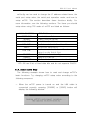
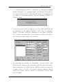
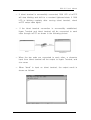
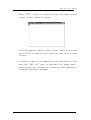
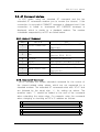
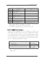
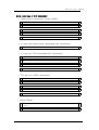
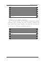
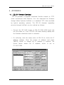
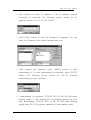
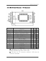
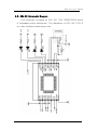
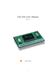
ezTCP/Ethernet (EZL-50)
User's Manual
Revision 1.6C
Sollae Systems
Table of Contents
1. Overview ················································································································· 1
1.1. Components ····································································································· 1
1.2. Specifications ·································································································· 1
1.3. Exterior of EZL-50 ······················································································ 1
1.4. Installation ······································································································· 2
1.5. Feature Overview ························································································· 2
2. Getting Started with ezTCP ············································································· 3
2.1. ezTCP Configuration ···················································································· 3
2.1.1. ezConfig ····································································································· 3
2.1.2. Basic Function Setup ············································································ 5
2.2. Communication Test ···················································································· 7
3. Advanced Function of ezTCP ······································································· 10
3.1. Serial Port Interface ·················································································· 10
3.1.1. T2S (TCP to Serial) ··········································································· 10
3.1.2. ATC (AT Command) ··········································································· 10
3.1.3. COD (Connect On Demand) ····························································· 11
3.1.4. TCP Connection Time Out (TIME OUT) ···································· 11
3.2. AT Command Interface ············································································ 13
3.2.1. Basic AT Command ············································································ 13
3.2.2. Extended AT Command ···································································· 13
3.2.3. AT COMMAND Escape Sequence ················································· 14
3.2.4. Examples of ATC Application ························································· 15
3.3. Environment Setup ····················································································· 17
3.3.1. Environment Setup in ATC mode ·················································· 17
3.3.2. IP Address-related Item Setup through DHCP Server ··········· 18
3.3.3. IP Address-related Item under Environment with ADSL ····· 18
3.4. ezTCP Environment Setup Item ···························································· 19
3.4.1. Network related Setup Item ···························································· 19
3.4.2. Serial Port Setup Item ······································································· 19
3.4.3. Serial Port Interface related Item ················································· 20
3.4.4. Miscellaneous ························································································ 20
3.4.5. STATUS LED State Variation ························································· 20
4. APPENDIX ············································································································ 22
4.1. EZL-50 Firmware Download ·································································· 22
4.2. EZL-50 Board Dimension / PIN Assignment ··································· 24
4.3. EZL-50 Schematic Diagram ··································································· 25
EZL-50 User's Manual
1. Overview
1.1. Components
☞ EZL-50 Main body
☞ EZP-50 EVB (Optional)
☞ RS232 Cable (provided with EVB)
☞ DC 5V SMPS Power Adaptor (provided with EVB)
1.2. Specifications
☞ Processor : TS87C54X2 / TS87C51U2
☞ Memory : ROM 64K / RAM 32K
☞ Interface : 12Pin SIP X 2 (2mm pitch)
☞ Protocols : TCP/UDP/IP/ICMP, Ethernet, ARP, PPPoE,
DHCP
☞ Power : DC 5V ±10%
1.3. Exterior of EZL-50
1
EZL-50 User's Manual
1.4. Installation
☞ After the power is turned on, check that the STATUS LED is
blinking regularly. If LED is not turned on, check if EZL-50 is
inserted into EVB correctly.
☞ After checking LED, connect RS232 cable and 10Base-T cable
to each port of the main body separately, and then EZL-50 is
now available.
1.5. Feature Overview
EZL-50 (hereafter ezTCP) is a serial port to TCP/IP converter, in
which one serial port and one Ethernet port (10Base-T) are
installed. The serial port should be connected to a serial port of the
control unit (hereafter DTE) and the Ethernet port should be
connected to a switching hub (or dummy) compatible with the
10Base-T standard. The following figure outlined a serial to Ethernet
conversion system configured with ezTCP:
Management and
Control System
Terminal
OA instrument
If a host computer (hereafter a host) is connected to the TCP
port of ezTCP over an Ethernet network, the serial port of the DTE
is connected virtually to the TCP port of the host. Then, ezTCP will
function as an intermediate device between the serial port and the
TCP port.
2
EZL-50 User's Manual
2. Getting Started with ezTCP
2.1. ezTCP Configuration
This section describes how to configure and test T2S mode,
which is the most convenient mode among the serial port interfaces
of ezTCP. For more information about the other modes, see the
following sections.
2.1.1. ezConfig
ezConfig, an integrated management application for Windows,
allows you to change the basic environment information of EZL-50.
ezConfig can run on Microsoft Windows platform but may not
operate on some of the existing operating systems. The screen
below shows the initial screen of ezConfig:
3
EZL-50 User's Manual
Each button on ezConfig functions as follows:
☞
This
button
is
used
to
search
for
all
of
the
network-attached ezTCPs. The search results will be displayed
on the MAC ADDRESS LIST box and you can select an item
using a mouse or cursor as required. The value displayed on the
box indicates the MAC ADDRESS of each ezTCP. The selected
setup value of ezTCP will be displayed on the right side.
☞
You can see only the ezTCP configuration details if you
press this button after entering the 6-digit hexadecimal number
printed on the ezTCP main body in the MAC ADDRESS box. It is
useful when there are too many ezTCPs attached to the network
to search for one from the LIST box.
☞
This button is used to save the changed value in ezTCP
after modifying the configuration. Make sure not to press this
button during operating ezTCP since ezTCP will automatically be
reset right after its environment setup value is saved. Otherwise,
it may cause malfunction.
☞
This button is used to close ezConfig. You can also
close it by pressing ESC key on the keyboard.
☞
ezTCP provides User Authentication function to prevent
an unwanted person from modifying the configuration. The
authentication process is performed through the password string
verification. When entering or changing the password strings,
you can use this button. Changing the ezTCP configuration
details if a password has been entered requires the proper
password to be entered in the PASSWORD field.
☞
This button is used to read a dynamic variable value
during operating ezTCP. Pressing this button will display a new
window, where the time-lapse after the power is on, the current
IP address, and the data throughput of the serial port are
indicated. Double-clicking each item on the MAC ADDRESS LIST
will carry out the same function.
4
EZL-50 User's Manual
ezConfig can be used to change the IP address related items, the
serial port setup value, the serial port operation mode, and how to
setup ezTCP. This section describes these functions briefly. For
more information, see the following sections. The items you should
setup when using T2S mode of ezTCP are listed as follows:
LOCAL IP ADDRESS
SUBNET MASK
GATEWAY
ezTCP IP Address
Network Subnet Mask
Primary Network Gateway
BAUD RATE
Serial Port Baud Rate
DATA BITS
The Number of Serial Port Data Bit
PARITY
FLOW CTRL
Serial Port Data Parity
Whether to use the Hardware Transfer
MUX TYPE
Control on the Serial Port
ezTCP Serial Interface Type
TIMEOUT
Connection Time Out
LOCAL PORT
TCP Port Number for Connection Standby
※ EZL-50 has 8 bit of fixed data bits and do not supports PARITY.
2.1.2. Basic Function Setup
The following example shows how to read and change ezTCP's
basic functions. Try changing ezTCP setup value according to the
following sequence:
☞ When the ezTCP power is turned on and the LAN cable is
connected correctly, pressing [PROBE] or [READ] button will
display the following window:
5
EZL-50 User's Manual
☞ If a network-attached ezTCP is detected, the following message
will be displayed. If a message pops up indicating that there is
no response from ezTCP, check that the power is turned on and
the cable is connected correctly, then try pressing [PROBE] or
[READ] button.
☞ If more than one ezTCP is detected, ezTCP's MAC ADDRESS will
be displayed in the [MAC ADDRESS LIST] box on ezConfig.
Check if the MAC ADDRESS displayed in the [MAC ADDRESS
LIST] window corresponds to that printed on ezTCP main body.
The following screen shows this process:
☞ On ezConfig, set [LOCAL IP ADDRESS], [LOCAL PORT], and
the serial port setting to be consistent with the test environment.
After completing the setup, press [WRITE] button to save the
changed values in ezTCP. If an error message appears during
storing the setting, check if ezTCP is connected correctly, and
then try again.
6
EZL-50 User's Manual
☞ In Windows' MS-DOS prompt window, check the IP address is
set correctly by giving the PING command. If the ezTCP IP
address is set correctly, the PING results will be displayed as
follows. If a message, "Request timed out", is displayed, check
that IP address setup value again.
C:\>ping a.b.c.d
Pinging a.b.c.d with 32 bytes of data:
Reply from a.b.c.d: bytes=32 time=1ms TTL=64
Reply from a.b.c.d: bytes=32 time=1ms TTL=64
Reply from a.b.c.d: bytes=32 time=1ms TTL=64
Reply from a.b.c.d: bytes=32 time=1ms TTL=64
2.2. Communication Test
You can conduct a simple test using Hyper Terminal or telnet
terminal for Windows if the IP-related items of ezTCP are set
correctly through ezConfig. A communication test will be conducted
as follows:
☞ Connect the serial cable to the serial ports of both ezTCP and
PC respectively.
☞ Run Hyper Terminal, change the serial port baud rate, data bit,
parity bit and flow control, and then save the changed values.
Each setup value must correspond to those configured by
ezConfig.
☞
In
Windows'
MS-DOS
prompt
window,
run
telnet
terminal
according to the following process. Note that a.b.c.d is the
ezTCP IP address and xxxx is the value of ezTCP's [LOCAL
PORT]:
C:\>telnet a.b.c.d xxxx
7
EZL-50 User's Manual
☞ If telnet terminal is successfully connected, RUN LED of ezTCP
will stop blinking and shift to a constant lightened state. If RUN
LED is blinking regularly after running telnet terminal, check
ezTCP setup value again.
☞ If the telnet terminal connection is successfully established,
Hyper Terminal and telnet terminal will be connected to each
other through ezTCP as shown in the following picture:
☞ When the two ends are connected to each other, a character
input from telnet terminal will be output to Hyper Terminal, and
vice versa.
☞ When "abcd" is input on telnet terminal, the output result is
shown as follows:
8
EZL-50 User's Manual
☞ When "1234" is input from Hyper Terminal, the output result is
shown on telnet terminal as follows:
☞ If the text appears garbled, check if items related to the serial
port of ezTCP correspond to the serial port setup value of Hyper
Terminal.
☞ If nothing is input on the keyboard for specified period of time
when the [TIME OUT] value of ezConfig is set bigger than 0,
telnet terminal will terminate the connection while displaying a
connection termination message.
9
EZL-50 User's Manual
3. Advanced Function of ezTCP
3.1. Serial Port Interface
ezTCP supports three types of the serial communication interface
mode: T2S, ATC, and COD. In T2S and COD modes, you can use
ezTCP by simply connecting the serial port without modifying
existing equipments' software. While in ATC mode, the existing
equipments' software needs modifying. For ATC mode, the AT
emulation function is supported and it allows you to use ezTCP for
a standard modem. Those who have experienced with modem
operation will take advantage of the full ezTCP functions without
effort. You cannot change the interface mode through ezConfig;
however, you can select a certain mode by downloading and
upgrading the firmware, if required. The typical functions of each
mode are listed below. The note at the end of each paragraph
describes the items you should change through ezConfig when
using the relevant mode.
3.1.1. T2S (TCP to Serial)
In this mode, ezTCP always wait for a connection request from an
external device without voluntarily connecting itself to an external
server or PC. In case an external host is connected to the specified
port of ezTCP, ezTCP will connect the serial port to the TCP port.
That is, it transmits data from the serial port to the TCP port and
data from the TCP port to the serial port. This mode allows you to
use ezTCP without modifying the existing equipment's software while
using COD mode. In T2S mode, care should be taken that all data
from the DTE to the serial port will be ignored until a connection
from a certain external PC to ezTCP is established.
In T2S mode, User can limit peer host IP address(This function is
implemented from T2S V1.6C and ezConfig V2.2P). If peer IP
address set to 0.0.0.0, then there is no access limitation, otherwise
the only specific host can connect to EZL-50.
※ Setup Items: [TIME OUT], [LOCAL PORT], [PEER IP ADDRESS]
10
EZL-50 User's Manual
3.1.2. ATC (AT Command)
You can use ezTCP for a standard modem. The extended
commands supported by ezTCP allow you to designate the IP
address and the port number of a host on the Internet and connect
it through ATD (T) command. After designating the connection
standby port, using ATA command will also connect a host to
ezTCP. For more information, see the following sections.
※ Setup Items: [TIME OUT]
3.1.3. COD (Connect On Demand)
COD mode allows ezTCP to voluntarily connect with the TCP port
on an external PC or a server. When a DTE transmits data to the
serial port, ezTCP will attempt connecting with a certain TCP port
on the specified computer that already has IP address. If the
connection is successful, this mode will transmit data already
received from the serial port to the TCP port, and then exchange
data between the TCP port and the serial port like the T2S mode.
In COD mode, a TCP connection will begin when the size of data
received from the serial port exceeds the pre-specified size (water
mark), and the size is changeable (factory-set value is 1 byte). If
the setup value is 0, a connection will begin right after the power is
turned on.
※ Setup Items: [TIMEOUT], [WATER MARK], [PEER PORT], [PEER
IP ADDRESS]
3.1.4. TCP Connection Time Out (TIME OUT)
ezTCP will terminate the connection if there is no data exchange
for a specified period of time. The time period can be selected
from 1 to 600 seconds, and the Time Out function is cleared if the
time period is set to 0 second. If the Time Out is set to 10
seconds, the connection will be terminated after ten seconds when
transmitting the last data. If the Time Out function is cleared, some
11
EZL-50 User's Manual
problem may occur because the TCP connection status of ezTCP
will remain unterminated when a host connected to ezTCP is shut
down abnormally. If the Time Out is set to 0, the Keep-alive
function on the TCP will be activated while the Time Out function is
cleared. The Keep-alive transmits the keep-alive packets and waits
for their responses if there is no data exchange for a specified
period of time. If no responses to the keep-alive packets are
received consecutively for five times, it will forcibly terminate the
current TCP connection. You do not need to pay attention to this
operation
since
it
is
the
internal
TCP
module
function.
The
keep-alive function is optional for the TCP/IP protocol specification.
On some operating systems, this function may not be available. If
you want to terminate the connection from ezTCP in COD mode, it
is recommended to use the Time Out function.
12
EZL-50 User's Manual
3.2. AT Command Interface
In ATC mode, using the standard AT command and the ten
extended AT commands enables you to access the Internet. If the
connection is successful CONNECT message is displayed and if the
connection is failed or terminated NO CARRIER message is
displayed, which is similar to a standard modem. The modem
commands supported by ezTCP are listed below:
3.2.1. Basic AT Command
Command
Function
Note
Connection Standby (Host → ezTCP
A
passive connection
D
active connection
E
echo
H
off-hook
character (E0-N, E1-Y)
Forcible Disconnection
I
Inquiry
ezTCP related information output
O
Online
V
enable result code
Online Command state → Online
Result Code Form (Number-V0,
Z
reset
connection)
ezTCP → Host connection
Whether to echo the input
Character-V1)
ezTCP Initialization
3.2.2. Extended AT Command
ezTCP provides the unique extended command for the control of
the Internet-related setup values, which are not supported by a
standard modem. The extended AT commands start with 'AT+P' and
are followed by the equal sign, '=', for setting up values. The
question mark, '?', should be added to the end of the command
when outputting the setup value. For example, enter the command
when changing or checking ezTCP's IP address as follows:
AT+PLIP=a.b.c.d
▶
◀ OK
▶
AT+PLIP?
◀ a.b.c.d
13
EZL-50 User's Manual
The extended commands available on ATC mode are listed below:
Command
Function
Note
+PLIP
local IP address
+PSM
subnet mask
+PGIP
default router
+PLP
listening TCP port
+PTO
timeout
+PRIP
Remote machine IP address
+PRP
Remote machine TCP port
+PWP
Write configuration
Saving the Setup Value
※ Setup Value ON/OFF Command: PRC (EZCFG), PARP (ARP),
PDC (DHCP), PPE (PPPoE), and PRL (TELNET)
※ The ON/OFF commands are set to ON (1) or OFF (0).
3.2.3. AT COMMAND Escape Sequence
When forcibly terminating the TCP connection of ezTCP, you
should shift the online state to the online command state through
'+++' escape sequence. Under the online command state, entering
ATH will terminate the TCP connection and entering ATO will restore
it to the online state. The guard times are required before and after
the '+++' character transmission as follows:
Until inputting the first '+' after the last More
than
500
data transmission
milliseconds
‘+’ input interval
0~500 milliseconds
The delayed time after inputting the last ‘+’
More
than
500
milliseconds
※ Note: The figures above require the guard time be set to 500
milliseconds.
14
EZL-50 User's Manual
3.2.4. Examples of ATC Application
☞ Telnet server connection (client mode):
AT+PRIP=aa.bb.cc.dd
☜ Telnet Server IP Address
▶
AT+PRP=23
☜ Telnet Port Number
▶
ATDT
▶
◀ CONNECT
◀ Data transmission/reception
▶
* In case the telnet server terminates the connection:
◀ NO CARRIER
* In case the DTE terminates the connection:
<guard time> '+++' <guard time>
▶
◀ OK
ATH
☜ Connection Termination
▶
◀ OK
☞ TCP port no. 6000 connection:
AT+PRIP=aa.bb.cc.dd
☜ Server IP Address
▶
AT+PRP=6000
☜ Port Number
▶
ATDT
▶
◀ CONNECT
◀ Data Transmission/Reception
▶
☞ Server Mode:
AT+PLP=6000
☜ Connection Standby Port Number
Setting
◀ OK
15
▶
EZL-50 User's Manual
ATA
▶
Connection Standby.....
◀ CONNECT
☜ Connection from external to ezTCP
◀ Data Transmission/Reception
◀
NO CARRIER
▶
☜ The connection is terminated by the
other end.
☞ Examples of using Multiple Commands:
Like a standard modem, ezTCP supports simultaneous multiple
commands input. Forbidding the echo command, outputting the
return value as the number instead of the string, and connecting to
the TCP port no. 6000 are exemplified as follows:
ATE
☜ Echo forbidden
▶
◀ OK
ATV+PRIP=aa.bb.cc.dd+PRP=6000DT
actually.
☜ Echo is not activated
▶
◀ 1
◀ Data Transmission/Reception
▶
16
EZL-50 User's Manual
3.3. Environment Setup
Environment variables such as the IP address, the serial port rate,
and the connection port number can be changed through AT
command or ezConfig.
3.3.1. Environment Setup in ATC mode
After changing the environment setup value, you must use the
+PWP command. +PWP is used to store the changed value in the
actual EEPROM. If the ezTCP power is turned on or EEPROM
configuration
is
changed
by
+PWP
command,
NO
CARRIER
message is displayed. The examples listed below are for setting
each item:
AT+PLIP=aa.bb.cc.dd
☜ ezTCP's IP Address
▶
☜ Gateway IP Address
▶
☜ Subnet Mask
▶
◀ OK
AT+PGIP=bb.cc.dd.ee
◀ OK
AT+PSM=255.255.255.0
◀ OK
AT+PLP=1470
☜ ezTCP's Listening TCP Port ▶
◀ OK
AT+PTO=10
☜ Reception Time Out
▶
☜ Storing the Setup Value
▶
◀ OK
AT+PWP
◀ OK
◀ NO CARRIER
17
EZL-50 User's Manual
3.3.2. IP Address-related Item Setup through DHCP Server
Under environment with a network operating a DHCP server, DHCP
protocol allows you to automatically set the IP address, subnet
mask, gateway, and name server of ezTCP. Using DHCP automatic
setup function requires you to check [DHCP] item on ezConfig.
Note that you may have to check [ARP] item according to the type
of DHCP servers.
3.3.3. IP Address-related Item Setup under Environment with ADSL
The data transmission/reception and IP allocation over ADSL are
typically based on PPPoE protocol, which is embedded in ezTCP.
PPPoE mode is activated by checking [PPPoE] item on ezConfig. If
the ADSL modem independently supports the PPPoE communication
function or an IP sharer is used, you should use this function
through a fixed IP or DHCP without checking [PPPoE].
18
EZL-50 User's Manual
3.4. ezTCP Environment Setup Item
3.4.1. Network related Setup Item
Setup Item
EZCFG*
ARP
**
DHCP
PPPOE
Description
Enabling the remote setup by using ezConfig
(Y/N)
Enabling IP Modification by using ARP (Y/N)
Enabling the automatic IP-related Item Setup
by using DHCP (Y/N)
Using PPPoE environment (Y/N)
USERNAME
ADSL (PPPoE) User ID
PASSWORD
ADSL (PPPoE) User Password
LOCAL IP
ezTCP's IP Address
SUBNET MASK IP Network Subnet Mask
GATEWAY
*
Primary Network Gateway
If you set EZCFG item to NO, searching for ezTCP or changing
the setup value through ezConfig will not be available.
** You may have to set ARP item to "YES" depending on the types
of DHCP server when using DHCP function.
3.4.2. Serial Port Setup Item
Setup Item
BAUD RATE
PARITY
DATA BITS
RTSCTS*
Description
Serial Port Rate (1200 ~ 115200)
Parity Bit: 0 (null), 1 (even number), 2 (odd
number)
Data Bit: 7 ~ 8
Using Hardware Flow Control (Y/N)
※ Changing DATA BITS, STOP bit, PARITY is not available.
※ XON/OFF Flow Control is not supported.
19
EZL-50 User's Manual
3.4.3. Serial Port Interface related Item
Setup Item
Description
TIME OUT
Connection Time Out
MUX TYPE
T2S (0), ATC (1), COD (2)
TCP Port Number for Connection Standby in
LOCAL PORT
WATER MARK
PEER IP
PEER PORT
T2S Mode
If the amount of data specified in watermark is
received from the serial port in COD mode, the
computer that is assigned IP address
previously will be connected.
IP address, to which ezTCP will attempt TCP
access, when using COD mode
TCP port, to which ezTCP will attempt
connecting, when using COD mode.
3.4.4. Miscellaneous
Setup Item
TELNET
PASSWORD*
Description
Connecting to ezTCP through telnet (Y/N)
Password String for User Authentication when
accessing telnet or changing ezConfig
configuration
※ Note: You can enter password up to 8 characters in English
language. If you forgot the password, you can modify or delete
the password by turning the power on or pressing the Reset
button when the ISP jumper is connected.
3.4.5. STATUS LED State Variation
☞ Fixed IP: Blinking 1 time per 1 second
☞ DHCP: Blinking 4 times briefly until the IP address is assigned.
Blinking 1 time per 1 second after the IP address is assigned.
☞ PPPoE: Blinking 4 times briefly in the normal state, 1 time per 1
second when the IP address is successfully assigned after
attempting a connection in ATC/COD mode, 4 times briefly after
returning the IP address when the connection is terminated.
☞ If a TCP connection is successfully established irrespective of
the IP allocation scheme, [STATUS LED] is turned on. If the
20
EZL-50 User's Manual
TCP connection is terminated, LED will start blinking again.
21
EZL-50 User's Manual
4. APPENDIX
4.1. EZL-50 Firmware Download
EZL-50 provides a firmware download function based on TFTP
under environment with Ethernet. You can download the firmware
through Sollae Systems HotFlash or a standard TFTP client provided
by
typical
operating
systems.
The
EZL-50
firmware
upgrading
process through HotFlash can be outlined as follows:
☞ Connect the ISP (JP3) jumper of EZL-50 EVB (LOW input) and
turn the power on. Then, STATUS LED starts blinking rapidly and
the firmware download mode is activated.
☞ On ezConfig, read the setup value of EZL-50 to check the IP
address
settings.
Enter
the
proper
IP
address
and
press
[WRITE] button to change the IP address, if required. The
screen
below
shows
the
211.44.13.248:
22
IP
address,
which
is
set
to
EZL-50 User's Manual
☞ Run HotFlash to enter IP address in the IP address window
according to ezConfig. The following picture shows the IP
address, which is set to 211.44.13.248:
☞ Press [FILE] button to read the firmware to upgrade. You can
down the firmware from Sollae Systems web site.
☞
After
reading
the
firmware,
press
[SEND]
button
to
start
downloading it. To stop downloading the firmware, press [STOP]
button.
The
following
picture
shows
the
EZL-50
firmware
downloading through HotFlash.
☞ If downloading is successful, [STATUS LED] of EZL-50 EVB starts
blinking slowly. If CRC checking of the firmware detects an error
after downloading, [STATUS LED] of EZL-50 EVB starts blinking
rapidly while EZL-50 continues operating in downloading mode.
23
EZL-50 User's Manual
4.2. EZL-50 Board Dimension / PIN Assignment
PIN NAME
TP_IN+
TP_INTP_OUTTP_OUT+
RX_LED+
TX_LED+
LINK_LEDSTATUS
RST+
P0
P1
ISPTxD
RTS
RxD
CTS
Functions
I/O
Stan Opti
dard onal
10Base-T Differential Input +
IN
●
10Base-T Differential Input IN
●
10Base-T Differential Output OUT ●
10Base-T Differential Output +
OUT ●
10Base-T RX Indicator
OUT
●
10Base-T TX Indicator
OUT
●
10Base-T Link Indicator
OUT
●
EZL-50 Status
OUT
●
Reset (Active High)
IN
●
Connect Notifier (Active Low)
OUT
●
reserved
In System Programming (Active Low) IN
●
UART TxD
OUT ●
UART RTS
OUT
●
UART RxD
IN
●
UART CTS
IN
●
※ ISP: Maintaining the internal Pull-Up state and shifting to the
firmware download state when LOW is input
※ P0: LOW when the TCP connection continued / HIGH when the
connection terminated
24
EZL-50 User's Manual
4.3. EZL-50 Schematic Diagram
- This schematic is based on P02-102-17C9 (SPEEDTECH) which
is embedded pulse-transformer. The datasheet of P02-102-17C9 is
our web site(http://www.eztcp.com).
25