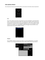
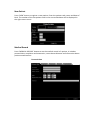
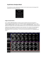
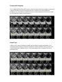
1
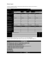
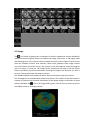
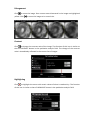
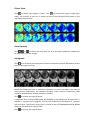
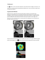
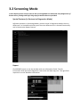
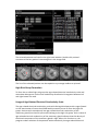
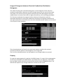
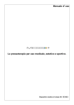
ELECTRICAL IMPEDANCE COMPUTER MAMMOGRAPH MEIK® 5.6 USER MANUAL CE1023 PKF «Modern Impedance Medical Equipment» www.impedance.ru All rights reserved. No part of this document may be copied, reproduced or distributed in any form without express written permission from PKF SIM-technika. PERMITS AND REGULATORY DOCUMENTS PKF "SIM‐technika" Ltd possesses medical equipment manufacturing licence (Registration Number 99‐03‐002246, December 9, 2010 with appendices). Electrical impedance computer mammograph MEIK® 5.0 for mammary gland screening by means of electrical conductivity distribution pattern visualization with software version 5.6 (hereinafter referred to as MEIK® 5.0) is granted with the registration certificate # 29/050010303/5420‐03 dated July 3, 2003 and the Declaration of Conformity № РОСС RU.ИМ02.Д00518 dated September 26, 2012. The safety of MEIK® 5.0 with software version 5.6 was certified according to Council Directive 93/42 EEC MDD by ITC (Czech Republic). MEIK® was awarded with the European certificate CE 1023 with the right to affix the CE marking right at the production. Quality Management System implemented by OOO PKF "SIM‐technika" is certified by DQS, Germany and conforms to the requirements of ISO 9001:2008, EN ISO 13485:2003 + AC:2009. MEIK® software version 5.6 is officially registered in the Russian Federation with Registration Certificate # 2009611472. Trademarks and logos of “SIM‐Technika” and “MEIK”® officially registered in the Russian Federation and are the property of OOO PKF "SIM‐technika" Ltd. MEIK® 5.0 is manufactured according to TU 9442‐001‐18100676‐2003 as amended. MEIK® 5.0 is protected by Eurasian patent for the invention # 012 006 with the priority right from July 5, 2007. All references to trade names of other companies within this User Manual are provided for their identification solely without any infringement of their rights and shall not be considered as a commercial or an advertisement. Table of Contents Introduction....................................................................... 5 Product Features ........................................................................................ 5 Product operation .................................................. 7 How to Prepare the Device for Operation................................................. 8 Software installation ..................................................................... 8 Connection to PC........................................................................... 8 Patient’s Data Input ...................................................................... 9 Patient’s Card Filling ..................................................................... 9 Measurements ............................................................................ 10 Patient’s Preparation ............................................................................... 11 Patient’s Position ........................................................................ 11 Breast Position ............................................................................ 11 Moistening .................................................................................. 11 Remote Electrode ....................................................................... 11 Electrodes Panel Fixation ............................................................ 11 Note............................................................................................. 12 Mammary Gland Examination ................................................................. 13 Beginning Measurement............................................................. 13 Last Measurements..................................................................... 13 Measurement Duration .............................................................. 13 Image Reconstruction............................................................................... 14 Reconstruction Method Selection .............................................. 14 Reconstruction Duration ............................................................. 14 Adding Comments....................................................................... 14 Software Operation........................................... 15 Diagnostics Mode.................................................. 15 Control Buttons Field................................................................................ 15 Information Block ..................................................................................... 16 List ............................................................................................... 16 Search.......................................................................................... 16 New Patient................................................................................. 17 Patient’s Card .............................................................................. 18 Archive ........................................................................................ 20 Measurement.............................................................................. 20 Information ................................................................................. 21 Editing ......................................................................................... 21 Qualitative Analysis Block ........................................................................ 22 One‐Window Mode .................................................................... 22 Highlighting ................................................................................. 23 Contrast ....................................................................................... 23 Colour Scale................................................................................. 24 Parameters .................................................................................. 24 Quantitative Analysis Block ..................................................................... 24 Compound Histogram ................................................................. 25 Graph Type .................................................................................. 25 Comparison with Norm ............................................................... 26 Tomogram Comparison .............................................................. 27 Information Transmission Block .............................................................. 27 Report ......................................................................................... 27 Manual report ............................................................................. 28 Automatic Report........................................................................ 29 Print ............................................................................................. 30 Copying........................................................................................ 30 Add to Norm................................................................................ 31 Close the Session ...................................................................................... 31 Exit............................................................................................................. 31 Images Field .............................................................................................. 31 3‐D image .................................................................................... 32 Enlargement ................................................................................ 33 Contrast ....................................................................................... 33 Highlighting ................................................................................. 33 Colour Scale................................................................................. 34 Scale Capacity ............................................................................. 34 Histograms .................................................................................. 34 Attachment ................................................................................. 35 Additional Window ..................................................................... 35 Screening Mode........................................................ 36 Special Features (in Contrast to Diagnostics Mode) ................... 36 Examination Report .................................................................... 36 Definition of Screening ............................................................... 37 Diagnostic Criteria Unit ............................................................... 37 Early Diagnostics of Breast Cancer.............................................. 37 Usage of Electrical Conductivity Index ........................................ 37 High‐Risk Group Formation......................................................... 38 Usage of Age‐Related Electrical Conductivity Scale.................... 38 Usage of Divergence between Electrical Conductivity Distribution Histograms .................................................................................. 40 Copying........................................................................................ 40 1. Introduction MEIK® 5.0 with software version 5.6 calculates relative electrical conductivity of tissues which is the assessment criterion for physiological and pathologic processes in the mammary gland, such as cancer, fibrocystic disease, mastitis, physiological involution, lactation etc. 1.1 Device unpacking MEIK® 5.0 is supplied to the customer only after completion of all preparatory works, tested and in fully equipped. When the device arrives, unpack it immediately and check for any damage that may have occurred during transportation. Check the package contents with the enclosed Packing List. If any defect, fault or deficiency is found during the acceptance inspection, notify your dealer (sales representative) of the details immediately. 1.2 Safety Signs ‐ Refer to user manual/booklet ‐ General safety sign ‐ General prohibitory sign ‐ General warning sign ‐ Laser hazard Laser hazard Class 1 1.3 Device features Mode selection function: screening or diagnostics. Seven scan planes within the range from 0.4 cm to 4.6 cm. Visual evaluation of the image with the help of proper estimation procedure. Quantitative evaluation: mean electrical conductivity index and the histogram of electrical conductivity distribution. Function of contrastive image analysis: qualitative and quantitative evaluation of the obtained images. Function of phase image analysis: qualitative and quantitative evaluation of the obtained images during the different phases of the menstrual cycle. 3‐D (three‐dimensional) image: creating and viewing of 3‐D images of the mammary gland, saving option (image or video). Cancer markers: quantitative evaluation helping to diagnose early (nonpalpable) stages and qualitative criteria to diagnose palpable malignant tumors of the mammary gland. Non‐cancer markers – quantitative and qualitative criteria facilitating diagnostics of palpable benign tumors of the mammary gland. Nonparametric diagnostic criteria: quantitative evaluation enabling to diagnose nonneoplastic diseases of the mammary gland. Multiwindow mode: feature of simultaneous viewing and comparison of several images of a patient’s mammary gland. Making of the examination report in manual or automatic mode: feature of automatic creation of the report with the help of embedded diagnostic algorithm. Feature of automatic screening report creation with the use of preset criteria. Feature of adding to the system images acquired with the help of other diagnostic methods (ultrasound, X‐ray etc.): adding and saving the images for further integrated assessment of the pathology. Archive creation feature (images, measurement): organizing a database containing images and measurement results for any pathology or norm. Image copy feature (to any storage medium). Sending images via e‐mail feature. Selected norm validation feature: evaluation of the selected reference norm according to statistical criteria to enhance diagnostics. When selecting a computer for use with MEIK, please, follow the requirements listed below, in order to fully benefit from all the functions of the device and to get high operating characteristics: • • • • • • • • Intel Pentium IV or higher processor (or compatible) At least 1 GB of system memory (RAM) At least 500 MB available hard disk space At least 1024х768 flat LCD (full‐screen) colour monitor Available USB‐port Video adapter with 3D hardware graphics acceleration with at least 128 MB memory Supported operating systems: Windows XP Service Pack 2, Windows Vista, Windows 7 At least 120 GB external hard disk drive for data backup is highly recommended To avoid mutual interference, do not position MEIK close to high‐power devices (e.g. power lines), as this may adversely affect the quality of visualization 2. Device operation This chapter is focused on the essential information on the patient preparation for examination and the directions on how to conduct the examination procedure correctly. Please, before operating the device carefully read this entire Manual. 2.1 PRODUCT SETUP Before operating the device keep it in the working area for at least 4 hours. Set up the device: Unpack the device. Remove ties from the USB cable and the patient’s coupling cable. Place the device together with the base on a plane surface close to the computer. Process the device using the following disinfectants: ‐ in Russia ‐ the alcohol pads that came with the device or CIDEX OPA, CIDEX PLUS, or “Meliseptol Rapid”, ‐ in Europe, Canada and the U.S. – the following disinfectants: CIDEX OPA, CIDEX PLUS. The procedure is the following: Wipe the device base with the disinfectant. Take MEIK® 5.0 in the left hand, the cable down, and process the electrodes array and the bottom of device body. Place the device on the base and process the remote electrode. Note: the listed above disinfectants are highly effective, have no adverse effects on the skin and human mucous membranes, do not require ventilation, do not leave a film on the electrode surface and do not change its electrical properties. Disinfection of the electrodes array and the bottom of device body, having contact with skin is required after each examination and upon completing of operation. When disinfecting, the device shall be disconnected from the computer. When processing the device, please, follow the instructions of the disinfectant manufacturer. Try not to exceed the expenditure rate of solution or spray. Connect the cable of the remote electrode to MEIK ® 5.0. The red dot found on the high‐precision latching connector LEMO (Switzerland) shall face the red dot on the socket of the device in order to achieve proper connection. When needed to disconnect the patient’s coupling cable from the device, install the device on the base, pull the ribbed clutch and remove the plug from the socket. How to Prepare the Device for Operation Software installation Install the program in your computer from the CD, following the instruction. Connection to PC Connect the device to the computer with a cable through a USB port. Use a plug to connect the external electrode with the device. The green light on the upper panel of the mammograph indicates that the power is on. Patient’s Data Input Run MEIK software on your PC. Two fields will appear on the screen: image and controls field. In order to enter a new patient, click “NEW” and enter the patient code, name and date of birth. Patient’s Card Filling Then click “PATIENT'S CARD” and fill in the medical card of a patient. 2.2 PATIENT PREPARATION 2.2.1 Patient position The examination is carried out on the massage couch, the patient in a supine position. Patients with small mammary glands may be examined in sitting position. 2.2.2 Breast position The mammary gland shall be levelled frontally. For this reason, the patient’s arm nearest to the breast under examination shall be placed behind her neck. The nipple shall be centred. 2.2.3 Moistening The mammary gland shall be moistened with water, water drops shall be avoided. 2.2.4 Gel electrodes application Apply disposable hydrogel electrodes to the forearm of an opposite arm or put the cylindrical electrode to the opposite hand of the patient. Mind that the arm should not be touching the patient’s body. ECG‐electrodes “SKINTACT”® F‐55 or “MEDI‐TRACE”™ or “1700 CLEARTRACE”™ are recommended to be used as disposable gel electrodes. Do not reuse the electrodes. Do not use dried electrodes or electrodes past their expiration date. Do not apply excessive force when disconnecting disposable electrodes from push‐ button latches to avoid cable breaking. Measurements Specify measurement conditions. After pressing "Start" button on the device or in "Measurement conditions" dialog box the device switches into the standby mode that is indicated with flashing yellow LED. Laser marker in the centre of electrodes array is activated. In the image field there is displayed an oval with red dots corresponding to the number of electrodes of the electrode array. Laser hazard Class 1 The device features a low‐power laser pointer with advanced radiation protection. Avoid looking into the laser beam! Do not point it into the eyes of the patient and onto reflective surfaces! Electrodes array positioning The electrodes array is placed against the breast in such a way that the laser marker is positioned on the nipple. It is necessary to achieve the minimal number of poor contacts (good contacts are displayed as green dots on the screen). Do not apply excessive force when positioning electrodes array at the breast to avoid hurting patient. Note If the mammary gland is not completely covered by the panel, the examination must be carried out by segments, clockwise (upper – external – lower – internal segment of the mammary gland). In order to obtain correct position of the image in the screen (from top to bottom corresponding the direction from head to legs), please, position the device in such a way that the side with the connectors was aimed at the feet of the patient. Mammary Gland Examination Beginning Measurement Press “START” button on the screen or on the device to begin the measurement. The yellow LED indicates that that the measurement is in progress during all the process of scanning. The laser marker switches off automatically when the measurement begins. Recent Measurements In the upper left corner of the image field there are displayed the last three images of the gland in the current session. Measurement Duration Measurement duration is about 35 seconds. Image Reconstruction Reconstruction Method Selection After the measurement is completed, please, select the method of image reconstruction. When the message appears on the screen, the mammograph may be removed from the breast. Reconstruction Duration Reconstruction process duration is about 1 minute and depends on PC characteristics. Adding Comments After the reconstruction is completed, the comments window appears together with seven scan planes in the image field. 3. MEIK SOFTWARE OPERATION (VERSION 5.6) This chapter considers all program controls in diagnostics and screening mode. The operating mode can be selected according to the purposes of the current examination. 3.1 Diagnostics Mode This chapter introduces the controls of Diagnostic Mode. The information on such features as image processing, quantitative analysis, database creation, copying and sending examination results is provided. Control Buttons Field Control buttons are arranged into several groups depending on functional features: information field, qualitative analysis field, quantitative analysis field, and data transfer field. Information Block The information field consists of eight buttons and contains information about the patients. List Click “LIST” button to see the list of patients from current database in code ascending order. A tooltip with information about the measurement appears when pointing any item of the list with the mouse cursor in all dialog boxes. If the code of a patient under consideration is found in the list (highlighted with blue colour), the tomograms of the breast can be loaded in the image field by double‐clicking the mouse button on the selected code or by clicking “ACCEPT” button. Search Click “SEARCH” button to search for a patient in a current database (or in any other database if you change the achieve) by name, patient code or date of examination. New Patient Press “NEW” button to register a new patient. Enter the patient code, name and date of birth. The number of the last patient code in the current database will be displayed in the right screen corner. Medical Record Press “MEDICAL RECORD” button to see the medical record of a patient. It includes personal data, complaints and anamnesis, recent breast diseases and information about previous examinations. Personal data Complaints Anamnesis Diseases of the Breast Examinations Archive "ARCHIVE" button enables to change the current archive or database. Press "BROWSE" to locate and load an archive, then click "OK" button. Pressing and holding "Ctrl" button enables to change the NORM database – the title bar will change to “Norm selection". Measurement Click "MEASUREMENT" button to proceed to mammary gland scanning. The following scanning conditions are to be set before the scanning: patient’s position and side of scanning (right or left), physiological period, specifying either the day of the menstrual cycle or the length of the menopause (both are counted automatically after entering the date of the last menses), the duration of gestation or the day and month of lactation If necessary, click “+” in the right upper corner to select the segment of the gland to be scanned. Information "INFORMATION" button enables to obtain information about any series of measurements: the file name of the given scanning series, the code number, the patient’s name and age, examination date and comments. Editing "EDIT" button enables to edit patient’s personal data: code number, name and date of birth. Qualitative Analysis Block The qualitative analysis field has five buttons and is used to process the images of all examination series simultaneously. Single‐window Mode Press "SINGLE‐WINDOW MODE" to display a series of measurements of the patient’s mammary gland executed under certain conditions (date, physiological period, etc.). Press "SINGLE‐WINDOW MODE" button again to go into "MULTI‐WINDOW MODE", which allows to add several windows with other measurements to the current measurement window to make comparison and subsequent calculations more convenient. For instance, the mammograms obtained during the first phase of the menstrual cycle can be complemented with the mammograms of the second phase. In this case new measurements will be highlighted with colour. Highlighting "HIGHLIGHTING" button enables to highlight the areas with certain electric conductivity. The minimal (lower) and the maximal (upper) range values are to be entered. The selected range is saved by default for further operations. The electric conductivity range typical of cancer is set by default in the program. "FLOATING ONCO‐MARKER" setting enables to search for and to highlight the areas of high electric conductivity typical of cancer on all the scan planes taking into account mean electric conductivity on each scan plane. The mode selected is saved by default for further operations. Contrast “CONTRAST” button enables to change the contrast ratio of the image. There are several presets helping to diagnose a number of diseases (cysts, cancer and infiltration). The "INVERTING SCALE" setting transforms positive images into negative, which facilitates image analysis. To change the image contrast ratio, move the left or the right slider until the required value is reached and click "OK" button. Press "RESTORE" button to restore the original values. Colour Scale "COLOUR SCALE" button enables to display the images in colour. Blue colour corresponds to minimum values of electric conductivity, while red colour indicates maximum values. Press "GREY SCALE" button to restore the original values. Parameters "PARAMETERS" button allows to display contrast ratio and the selected range values set up by the user as well as to show grey or colour scale of electric conductivity. Quantitative Analysis Block Quantitative analysis field has four buttons and provides numerical information. Compound Histogram The "COMPOUND HISTOGRAM" button enables to preprocess the histogram converting a simple histogram into an enveloping one for its further use in the compound histogram, e.g., to compare it with the norm or another histogram. This action applies to the images of all series simultaneously. Graph Type "GRAPH TYPE" button enables to modify the histogram envelop and display it as a smoothed representation of electric conductivity values (GRAPH TYPE 1) as well as its unsmoothed values (GRAPH TYPE 2). This action applies to the images of all series simultaneously. Comparison with Norm The "COMPARISON WITH NORM" button enables to compare the patient’s histogram of electric conductivity distribution with the NORM histogram thereof. Conditions for creating the NORM histogram are to be selected before the comparison can be started. The right‐hand column contains the patient’s personal data. In the left‐hand column conditions of the normal histogram shall be ticked. The number of tomograms satisfying the conditions for histogram selection with characteristics of the NORM which are intended to be used for making up the compound histogram of electric conductivity distribution typical for the NORM is shown in the "SELECT" line. The total number of tomograms available in the NORM database is shown above that line. Click "OK" button to confirm the selection. The histogram of electric conductivity distribution for the NORM will be added to the patient’s histogram. Below the histograms there are statistical parameters of the patient’s mammary gland electric conductivity and these for the NORM: the index of mean electric conductivity, the standard deviation (STD), electric conductivity index minimum and maximum and the extremum (mode). The last line contains the ratio (in %) of divergence between the patient’s histogram of electric conductivity distribution and the histogram for the NORM, the ratio being calculated by the Smirnov‐Kolmogorov criterion. This action applies only to the histograms of current measurement. Tomogram Comparison "TOMOGRAM COMPARISON" button enables to compare the histograms against each other. The tomograms for comparison can be chosen by clicking the left button of the mouse. The selection of the tomograms and histograms of electric conductivity distribution in the mammary glands, intended for comparison, will be displayed in a separate window. Click “PRINT” button to print the images and histograms. Data Transfer Field Data transfer field has four buttons and provides various ways of data transfer. Report Click "REPORT" button to draw up an examination report and a medical conclusion. The procedure can be performed in manual or in automated mode. Manual report Choosing "MANUAL MODE" will display the table of the last report on the screen. It shall be filled in by the user. The most frequent diagnoses are specified in the “LIST OF DIAGNOSES”. Highlight them and press “ADD” button to move them to the “CONCLUSION” line. Press “ATTACH” button to attach the data obtained with the help of other diagnostic methods (ultrasonography, X‐ray examination) to the report. The following data can be attached: images, videos in any format or images acquired from the scanner connected to the computer. Attached data are marked by a paper clip on the image field. Press the corresponding hotkeys to save or print the final version of the report. Automated Report When "AUTOMATIC MODE" of reporting is selected, only the image and measurement analysis shall be done. Diagnostics is based on the expert system. After answering the questions of image and measurement assessment the conclusion is created by the software, which can be saved and printed, as in manual mode. Print Press PRINT button to print selected images. Click left mouse button on the image to select it. The flashing caption will be displayed in the right upper corner of the screen showing the position of the image on the page, e.g., Page 1 Figure 1. Copying COPYING button enables to select necessary images and measurements to sort them in corresponding folders. The measurements are copied into the file compatible with «Microsoft Excel». Either a single current measurement or a series of measurements can be copied. On default files can be copied to various folders, but any folder containing diagnoses of interest can be selected to store the files with the help of BROWSE button. The data can be copied to any storage medium or can be sent via e‐mail. Add to Norm ADD TO NORM button enables to renew NORM database. Either a single measurement or a series of measurements can be copied can be added to NORM. Close Session CLOSE SESSION button serves for clearing image field. Exit Press EXIT to quit the current mode of operation. Images Field Upon the scanning procedure or the selection of patients from LIST seven images of the mammary gland appear in the image field. The images correspond to the scan planes set parallel to the electrodes plane, the depth increasing from 4 to 46 mm. The upper line contains the patient’s code and the numbers of scan planes with the correspondent depth, measured in mm. Each line of the image field contains 7 images, the number of lines is unlimited. The line above the images has a caption with the information on the given measurement series: date and time of examination, comments on the conditions of examination. The column to the left of the first scan plane images has a number of icons intended for various operations with the images (listed from top downward): 3D, zoom, contrast, highlighting, colour scale, scale capacity, and histograms. The icons are active for the selected line of images only. 3‐D image The icon allows for getting the visualization of electric conductivity volume distribution within the mammary gland tissues. On default the image is 64 colour. In 3D image mode the following icons in the vertical column located to the left of the images of the first scan plane are clickable: contrast, area selection, colour scale, gradation scale. Image controls are in the bottom part of the screen. The controls on the left enable to move the image as well as to zoom it in and out. The image can be moved with the help of the left mouse button: hold down your left mouse button and drag the image in the direction you wish it to move. You can also zoom the image in and out. The SHOW LAYER function enables to add or remove scan planes (layers) of interest. The 3D image can be printed and/or saved in any format. The creation of the video movie is necessary to preserve the electrical conductivity of the object during its movement. If saved data are available, the icon in the image field is green. Click the icon to see the menu for saved data review or 3D image creation. Enlargement Click to zoom the image. Poor contact areas discovered in the image are highlighted yellow. Click to return the image to its normal size. Contrast Click to change the contrast ratio of the image. The function of this icon is similar to that of CONTRAST button in the qualitative analysis field. The change of the contrast ratio is immediately reflected in the current line of images. Highlighting Click to highlight the areas with certain values of electric conductivity. The function of this icon is similar to that of HIGHLIGHT button in the qualitative analysis field. Colour Scale Click to display the images in colour. Click ; to restore the original image (grey scale). The function of this icon is similar to that of the COLOUR SCALE button in the qualitative analysis field. Scale Capacity Click , or to choose the scale with 16, 32 or 64 colour gradations respectively for operations with the images. Histograms Click icon to display the histogram of electric conductivity volume distribution within the mammary gland tissues. Below the histograms there is statistical information on each scan plane: the index of mean electric conductivity, the standard deviation (STD), electric conductivity index minimum and maximum and the extremum (mode). Click to restore the original values. is displayed after clicking COMPOUND HISTOGRAM in the quantitative analysis field. It enables to compare the histograms of electrical conductivity distribution of a patient with the norm. The function of this icon is similar to that of COMPARISON WITH NORM button in the qualitative analysis field. Click to restore the original values. Attachment Icon enables to view the data attached to the measurement (images or movies). The attachments can be viewed using Windows default tools. You may attach the data when creating your REPORT. Supplemental Window Double‐click any image with the left mouse button to open a new window with additional information (cursor coordinates and electrical conductivity at a given point). In addition, you can measure the dimensions of the area of interest. In order to do this press and hold left mouse button and select the area of interest in the image. The dimensions of the selected area (in centimetres) will be displayed in the second line of the table, within parentheses. There are icons on the left with the same functions as the icons in the image field but they apply to the current image only. Icon displays a three‐dimensional image of the current scan plane. 3.2 Screening Mode In this chapter all the controls used in the Screening Mode are observed. Early diagnostics of breast cancer findings and high‐risk group formation data are provided. Special Features (in Contrast to Diagnostics Mode) Software operation in Screening Mode is similar to that in Diagnostics Mode, the only difference is in limited functionality and The main difference lies in limited functionality and in Examination Report feature. Report Click REPORT button to see the window with two information fields. The left information field represents diagnostic criteria unit and data copy unit. The right field represents current database information. Definition of Screening World Health Organization defines screening as the presumptive identification of unrecognized disease or defects by means of tests, examinations, or other procedures that can be applied rapidly and for the large population groups. Screening examination enables to form the groups of people at risk for development of certain decease. A high‐ risk cancer group should be defined as the group of people in the community with symptoms of the so‐called "pre‐existing disease” which can be detected due to various reasons. The "pre‐existing disease” concept is of special importance in connection with the given opportunity to actively conduct cancer prevention measures already on such an early stage. Screening is a dynamic process. And in this connection, the usage of safe screening methods makes sense, because it enables to conduct multiple repeated examinations. Electrical impedance mammography is just the sort of method which can be repeatedly used to examine a patient. Diagnostic Criteria Unit Diagnostic criteria unit consists of the following: early diagnostics with the help of electrical conductivity index, high‐risk group formation with the help of the age‐related electrical conductivity scale and anomalous divergence between electrical conductivity distribution histograms of left and right mammary gland. Early Diagnostics of Breast Cancer Breast cancer can be diagnosed at an early stage owing to the usage of the electrical conductivity index. Usage of Electrical Conductivity Index If the method of diagnostics under examination permits to acquire a numerical result, the so‐called "breaking point" (the value exceeding of which is considered as a sufficient cause for qualitative assessment) should be determined. In this case the estimation of diagnostic technique efficiency may be limited to sensitivity and specificity assessment. Thus the accurate determination of the breaking point is extremely important. Electrical conductivity index ≥ 0.95 is considered as the cut‐off value between healthy mammary gland tissue and a noncomplicated tumour. In case the cut‐off value with electrical conductivity index ≥ 0.95, sensitivity is 84 ‐ 93% and specificity ‐ 87 ‐ 99% according to the data given by different authors). When this function on, the program makes selection of the patients with pathologically high focal electrical conductivity of the mammary gland (a characteristic feature of the small‐sized tumours) from the current database (base address can be found in the top line of the window). The selected patients are listed in the right‐hand window. Double‐click patient’s surname to load any patient’s mammogram in the image field. The list of the selected patients can be copied to any storage medium or printed. High‐Risk Group Formation To form the so‐called high‐risk group the age‐related electrical conductivity scale and anomalous divergence in electrical conductivity distribution histograms between left and right breast are used. Usage of Age‐Related Electrical Conductivity Scale The age‐related electrical conductivity scale with distinguished percentile ranges (based on the examination of more than 2000 healthy women) serves to form the high‐risk group. Patients with anomalously low age‐related electrical conductivity of the mammary gland (less than 5th percentile) belong to the high‐risk group. Such a value of age‐related electrical conductivity of the mammary gland indicates that the density of the ductal component of the mammary gland is high. When this function on, the program makes selection of the patients with anomalously low age‐related electrical conductivity of the mammary gland (less than 5th percentile) from the current database (base address can be found in the top line of the window). The selected patients are listed in the right‐hand window. Double‐click patient’s surname to load any patient’s mammogram in the image field. The list of the selected patients can be copied to any storage medium or printed. Usage of Divergence between Electrical Conductivity Distribution Histograms The indices showing the anomalous divergence in the histograms of the electrical conductivity distribution between the left and right breast are also used to form high‐ risk groups. The variance percent chosen with the help of the Kolmogorov‐Smirnov nonparametric test (more than 40%) is highly informative, j>3.0 according to Kullback. This function employed, the program makes selection of the patients with the anomalous divergence in electrical conductivity distribution histograms between left and right breast (more than 40%) from the current database (base address can be found in the top line of the window). The selected patients are listed in the right‐hand window. Double‐click patient’s surname to load any patient’s mammogram in the image field. The list of the selected patients can be copied to any storage medium or printed. Copying To copy the mammograms of a patient click COPY button. To copy all the mammograms of the current database click BASE button. On default files are copied to a new folder, but any folder can be selected to store the files with the help of BROWSE button. The data can be copied to any storage medium or can be sent via e‐mail. Ending operation Before logging off from current session, please: ensure that acquired data have been saved print out examination reports. Then: close program shut down the computer, turn surge protector off disinfect the device and its base in accordance with the recommendations (see p. 9). close the package with gel electrodes firmly. 4. CALIBRATION Primary calibration of the product is performed at the release of the device from the production line. Recommended interval for periodic calibration is 24 months. It is carried out at the request of the consumer at the production environment. 5. TROUBLESHOOTING MEIK® 5.0 is a high‐precision electronic instrument assembled using modern assembly equipment at the production area of OOO PKF "SIM‐technika" Ltd. by highly qualified personnel. Any failures caused during transportation, operation, or unforeseen circumstances, should be repaired only by the manufacturer at the production area after comprehensive testing and subsequent acceptance tests. Issue Possible cause Possible solution The emergence of yellow contact dots in fixed locations on the green contact field, which do not disappear when the device is reapplied to the mammary gland. 1. No contact between the spring‐ loaded electrodes and the multiplexer board inside the device. 2. Contact electrodes and device bottom greasing During the reconstruction or scanning process the matrix is filled in with yellow dots. Further operation is impossible. Poor moistening of the breast; or a dry ECG‐electrode; or wire breakage of the patient’s coupling cable Exposure to strong electromagnetic interference (transformers, power plants, discharges). 1. Return to OOO PKF "SIM‐ technika" Ltd for factory repair 2. Clean the electrodes and device bottom with ethyl alcohol or with the cleaning fluids recommended by the manufacturer. Return to OOO PKF "SIM‐ technika" Ltd for factory repair ‐ as adjustment or strengthening of EMI protection may be required Substantially increased scanning or image reconstruction time. System requirements mismatch (see this Manual), no free space available on HDD (if backup on remote HDD is not performed). If change of PC/laptop won’t help, return the device to OOO PKF "SIM‐technika" Ltd. for factory repair. For all technical issues and questions, please, contact OOO PKF "SIM‐technika" Ltd by phone / fax: + 4852 79 58 67 or e‐mail: sim‐[email protected]. Address: Russia, 150054, Yaroslavl region, Yaroslavl, 2 Chkalova St., office 223. 6. WARRANTY The manufacturer guarantees that the electrical impedance computer mammograph MEIK® 5.0 with Software Version 5.6 complies with the technical regulations of TU 9442‐ 001‐018100676‐2003 with amendments, provided that the consumer observes operating, handling and storing rules. Warranty lifetime ‐ 24 months from the date of purchase. In case the factory seal is broken, the manufacturer declines all the responsibility for the warranty repair of the device. Product life cycle till discarding – 5 years. At the expiration of product lifetime, by agreement with the customer, the complete modernization of the product may be performed by the Manufacturer with the replacement of major components and software. Product is labelled with a new serial number and the effective date of sale. Effective date is used to establish the beginning of product warranty period and service life. In the event of the refusal to undertake the abovementioned measures the manufacturer is not responsible for performance degradation due to ageing and as a consequence, degradation of diagnostic possibilities and diagnostic difficulties. Manufacturer: EU Representant: OOO PKF “SIM‐technika” Ltd 2 Chkalova St., office 223, Yaroslavl, 150054 Russia ONKOCET s.r.o. Kutuzovova 4 Pezinok, 902 01 Slovakia Tel.: +7 4852 795867 Fax: +7 4852 795867 www.impedance.ru E‐mail: sim‐[email protected] Tel.: +421 2 446 40977 Fax: +421 2 446 40977 www.onkocet.eu E‐mail: [email protected] Last revision: 28th September 2012