1
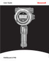
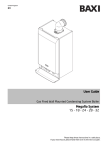
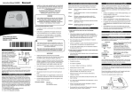
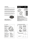
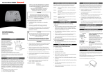
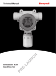
Operating and
Installation Instructions
About Flammable Gas
Thank you for purchasing this gas detector, which is designed for use in domestic premises (including
static caravan holiday homes) to detect leaks of flammable gas. The detector must be connected to
mains power.
Flammable gas is dangerous if the concentration builds up enough to become explosive. This level is
called the lower explosive limit (LEL). The HF500 detector will alarm if the gas concentration reaches 10
% of the lower explosive limit (10 %LEL).
This manual contains important safety information about the installation and operation of the detector.
Read the manual carefully and keep it in a safe place for future reference.
Note: Natural Gas and LPG have additives which gives them a distinctive smell. Most people are able to
smell Natural Gas or LPG at a lower concentration than the detector alarm setting. This does not mean
that the detector is faulty.
Warnings
• This gas detector must be installed by a competent person qualified to carry out electrical
work according to current national wiring regulations. Additionally, any changes to the gas
installation,e.g., fitting of an automatic gas shut-off valve, must be carried out by a person
qualified to the national regulations for gas installations.
Power
Alarm
Fault
• The gas installation and shut-off device (where used) must comply with the appropriate
national regulations.
Description
The detector has two relays, alarm and fault. The alarm relay can be used to activate an external device
such as a gas shut down valve, or an automatic signal such as a call to the emergency services.
The fault relay can be used to activate a signal to an external device such as a supervisory panel.
Contact Us
Methane Gas Detector HF500NG
Power
Please Note:
While every effort has been made to ensure
accuracy in this publication, no responsibility
can be accepted for errors or omissions. Data
may change, as well as legislation, and you are
strongly advised to obtain copies of the most
recently issued regulations, standards, and
guidelines. This publication is not intended to
form the basis of a contract.
If the alarm stops, check the following: -
Do not tamper with the detector – there is a risk of electric shock or damage to the detector.
1. Has the source of the gas leak been identified (for example a gas tap switched on with the burner
unlit)?
2. Has the gas leak been stopped?
If required, clean the surface of the detector with a lightly damped cloth. Do not use detergent as this
may damage the internal sensor.
If the answer to either of these questions is no, then notify the gas supplier or the gas emergency
service so that the installation may be tested and made safe, and any necessary repair carried out.
Summary Table
Condition
Power
Light
(Green)
Alarm
Light
(Red)
Fault Light
(Yellow)
Audible
Alarm
Power on,
no gas
OFF
ALARM,
gas
detected
Power
Fault
Sensor
Fault
Normal operation
ON
Gas detected
Intermittent
single chirp
There is a fault
with the electrical
installation
2 long chirps
per minute
Software
Fault
Meaning
Continuous
chirps
The detector must be
replaced
If your Detector is in alarm
UK GAS EMERGENCY SERVICE TELEPHONE NUMBER
0800 111 999
Tell the operator that your flammable gas detector is in alarm and you suspect that there is a
gas leak.
Extinguish all naked flames, including all smoking material
Turn off all gas appliances
Do not switch on or off any electrical equipment, including the gas detector
Turn off the gas supply
Open doors and windows to increase ventilation
Do not use a telephone where gas may be present
If the alarm continues, and the cause of the leak cannot be found, vacate the premises and
IMMEDIATELY NOTIFY the gas supplier or the gas emergency service.
Recommended
replacement date
RAL 90 10 P ure White
12797
HF500NG
MAN0899_Issue 1_06/12_EMEAI
© 2012 Honeywell Analytics
TEST / HUSH
Replace unit by 01.2016
Precautions during use
Detector Operation - continued
If the detector is in FAULT (YELLOW light) it must not be used any more, and should be replaced. (The
exception is if the detector signals a Power Fault indicated by an intermittent single chirp. In this case
there may be a fault with the power supply and the electrical installation should be checked).
Test/
Hush button
Fault
Acts for and on behalf of Life Safety
Distribution AG, Javastrasse 2, 8604 Hegnau,
Switzerland by its Authorised Representative
Honeywell Inc.
If the detector is in ALARM and the gas clears, the detector will return to normal operation.
Audible alarm
Indicator lights
Alarm
UK customer service centre
NG - Natural Gas
LPG - Liquified Petroleum Gas
Detector Operation
•
•
•
•
•
•
Gas entry point
Caution: Read and follow manufacturers instructions carefully before operating or servicing
Honeywell Analytics Ltd.
4 Stinsford Road
Nuffield Industrial Estate
Poole, Dorset BH17 0RZ
Tel: +44 (0)1202 645577
Fax: +44 (0)1202 665331
[email protected]
LPG (Liquefied Petroleum Gas) is a mixture of primarily propane, primarily butane or both.
The gas is heavier than air, so any leak will result in a build up of gas at a low level. (This is why
the installer will place the detector near the floor)
If your detector is in ALARM, keep calm, and carry out the following actions, not necessarily in
the order given:
www.honeywellanalytics.com
www.hf500gasalarm.com
www.honeywell.com
HF500NG / HF500LPG
Residential Flammable Gas Detector
•
•
If the detector is in ALARM, the audible alarm can be silenced for 5 minutes by pressing the
TEST/HUSH button (the RED light will continue to flash). If gas is still present after 5 minutes, the
audible alarm will sound again.
The GREEN light indicates that the power to the detector is ON.
The RED light indicates that GAS has been detected.
The YELLOW light indicates that there is a FAULT with the detector.
TEST / HUSH
Natural Gas is primarily Methane
Natural Gas is lighter than air, so any leak will result in a build up of gas at a high level within a
room or enclosed area. (This is why the installer will place the detector near the ceiling)
If GAS is detected the RED ALARM light will flash and the audible alarm will sound.
The detector has three status indicator lights, an audible alarm and a test/hush button.
Replace unit by 01.2016
•
•
Some materials such as cleaning fluids, polishes, paints, cooking operations etc. may generate fumes
which could cause false alarms from the detector or affect its long term reliability. Avoid using these
substances close to the detector.
1
2
Disclaimer
Specification
This flammable gas detector is designed to alert you to a potentially dangerous build up of flammable
gas. It is not designed to remedy a flammable gas problem nor to locate a specific leak of flammable
gas. Honeywell shall not be liable to pay for any investigation or service call carried out or arranged in
response to an alarm.
Warranty
Warning
Honeywell warrants your new gas detector for two years from the date of purchase by the end user or
until the expiry date on the front of the unit, whichever occurs first, according to the specifications as
set out in this instruction manual.
Silicones can permanently damage the detector. Avoid using silicone sealant or any household or
cosmetic product containing silicone in the vicinity of the detector.
We will, at our discretion, repair or replace, with same or similar product, any part of the gas detector
which is found to be defective in either materials or workmanship within the warranty period.
Monthly Detector test
We shall be under no obligation to repair or replace units which are found to be defective in any way
due to unreasonable use or neglect, improper storage, used or maintained not in accordance with the
user manual or if the product has been tampered with or found to have been dismantled.
The detector should be tested once per month. To test the detector, press and hold the “TEST/HUSH”
button on the front cover for 1 second. The RED light will flash 4 times, and then the YELLOW light will
flash 4 times, accompanied by the audible alarm sounding 8 times.
Caution: Testing the detector with an uncontrolled source of gas (for example a cigarette lighter)
may give a misleading result and could damage the detector.
Conformance to European standards
The HF500NG Natural Gas detector and the HF500LPG Liquefied Petroleum Gas detector conform to
EN50194-1, which is the European Standard for electrical apparatus for the detection of combustible
gases in domestic premises. A full EC declaration of conformity is available at our website. Navigate to
www.honeywellanalytics.com and select Resources, then EC Declarations.
End of Life
The detector should operate for 5 years under normal use. The recommended
replacement date is shown on the front of the detector.
This warranty is instead of and excludes all warranties implied by law, and to the extent permitted by
law, our liability under the warranty is capped at the price of the product.
In no event are we liable for (a) any direct, indirect, incidental, consequential loss; (b) any loss arising
from business interruption; (c) loss of profits; (d) loss of revenue; (e) loss of use of any property or
capital; (f) loss of anticipated savings or loss of data.
Troubleshooting and getting assistance
After you have carefully read all instructions and your alarm still fails to work, contact the nearest
Customer Service listed in the “Contact Us” section, which might be able to resolve your problem
quickly. Alternatively contact your local supplier.
If the product needs to be returned for repair or replacement, put it in a padded box with a letter
describing the fault and postage paid. For battery powered devices, ensure that the alarm has been
switched-off.
Calibration Gas
Methane (Natural Gas Version), Propane (LPG Version)
Calibration Level
10% LEL (Lower Explosive Limit)
Sensor Technology
Catalytic combustion
Accuracy Tolerance
± 2.5% LEL
Dimensions
150mm x 104 mm x 40 mm
Weight
< 400 g
Installation
Surface mounting
Power
110 - 230 Vac 50/60 Hz
Power Consumption
< 6.5 W
Alarm Relay
5 A 250 Vac SPDT (single pole changeover)
Fault Relay
0.25A 250VAC SPST NO (single pole)
Temperature
-10 °C to +55 °C
Humidity
0-95% RH (non-condensing)
Test Facility
Yes
Self Check Function
Yes
A proof of purchase must be provided to claim repair under warranty.
When the unit has come to the end of its life, dispose of it in accordance with local
regulations. It is classified as electronic waste and should be disposed of separately from
household waste.
Gas appliances should be checked for safety annually by a Gas Safe registered engineer. To find a
registered engineer in your area call Gas Safe Register on 0800 408 5500 or look on the website:
www.gassaferegister.co.uk.
3
4
5
6
The detector should be installed in the room where a gas escape is most likely to occur. For most
installations the most likely source of a gas leak will be the cooker in the kitchen
•
This gas detector must be installed by a competent person qualified to carry out electrical
work according to current national wiring regulations. Additionally, any changes to the
gas installation, e.g., fitting of an automatic gas shut-off valve, must be carried out by a
person qualified to the national regulations for gas installations.
• The gas installation and shut-off device (where used) must comply with the appropriate
national regulations.
LPG
•
•
The installer should refer to the current edition of the European Standard EN 50244
“Electrical apparatus for the detection of combustible gases in domestic premises
– Guide on the selection, installation, use and maintenance.”
Caution: The installation must include some form of isolation switch.
Note: It is recommended that flexible cable is used, e.g. 1.0 mm2 core. For a surface mount
installation, the use of mini-trunking is recommended.
Natural Gas
• Natural Gas is lighter than air, so a leak of gas will build up at a high level. The detector should be
placed above the level of a possible gas escape and near the ceiling
• The detector should be placed above the highest window or door opening, usually not more than
30 cm from the ceiling
• The detector should be located between 1 m and 5 m from the gas appliance.
Installation - continued
The detector should be wired to the mains power supply using a flexible cable appropriately rated via a
fused connection outlet and fitted with a 3A fuse to BS1363-4 and BS1362 respectively, or according to
local regulations.
The power supply cabling and connections for the relays (if used) can be routed through the back of the
Mounting DRG
Plate,
or through knock-out holes (25 mm x 16 mm, quantity 4) at the bottom and the sides.
NO
1
If the knock-out holes are used, ensure that the IP2XD rating is maintained by using the correct size
trunking, or a suitable ferrule. The dimensions of the mounting hole locations within the Mounting Plate
are shown below.
Unpack the detector and check the contents: •
•
•
•
DRG NO
•
•
•
A
LPG is heavier than air, so a leak of gas will build up at a low level. The detector should be placed
below the level of a possible gas escape and near the floor level.
The detector should be located not more than 30 cm from the floor and not more than 4 m from
the gas appliance.
THIS DOCUMENT HAS BEEN GENERATED USING AutoCAD
SHT.
1
Detector
Mounting Plate
User Manual
Wood screws x 2 to attach the Mounting Plate to a wooden surface
SHT.
Anchor
plugs (6 mm) and masonry screws x 2 to attach the Mounting Plate to a masonry surface
Electrical screws x 2 to attach the Mounting Plate to an electrical outlet box
Assembly screws x 4 to attach the Detector to the Mounting Plate.
C
B
1
E
D
F
G
H
THIS DOCUMENT HAS BEEN GENERATED USING C.A.D
AND MUST ONLY BE UPDATED BY C.A.D.
2
30.5
Knock-Outs
Natural Gas Detector Installation
LPG Gas Detector Installation
AND MUST ONLY BE UPDATED BY C.A.D.
61
Warnings
Installation
83
Where to put the Detector
30.5
Installer Section - Introduction
Knock-Outs
61
83
118.5
Max 30 cm
Gas Detector
124.2
3
Gas Detector
Max 5 m
BEEN GENERATED USDING Relay Description
The HF500NG
HF500LPG
has two output
relays, one for Fault and one for Alarm. The relays provide a
D MUST
ONLY /BE
UPDATED
BY A.I.
1.
4
2.
Unswitched
fused outlet
Max 30 cm
5
Unswitched
fused outlet
The Mounting Plate contains the terminals for connecting the power supply and relay outputs. Once the
connections are made, the detector simply plugs into the Mounting Plate.
A
DRG NO
Where not to put the Detector
Caution: The detector must be tested regularly. Ensure that the user is able
to access the TEST/HUSH button.
SHT.
1
F
G
CONFIDENTIAL. IT IS THE
AND MUST ONLY BE UPDATED BY C.A.D.
THIS ITEM FORMS PART OF A CERTIFIED PRODUCT
NO MODIFICATION PERMITTED WITHOUT
REFERENCE TO CERTIFICATION DEPARTMENT
C
B
DRG NO
ALL DIMENSIONS IN D
MILLIMETERS UNLESS
OTHERWISE STATED.
AND APPLY AFTER PLATING
TOLERANCES TO BE AS
SPECIFIED BELOW UNLESS
OTHERWISE STATED.
AND MUST ONLY BE UPDATED BY C.A.D.
DIMS. 2DP ±
0.1 mm
1DP ±
0.25 mm
NONE ±
0.4 mm
ANGULAR ± 1/2°
HOLES.
0 to 8 +0.08 -0.0
8 to 14 +0.1 -0.0
14 to 25 +0.12 -0.0
THIS DOCUMENT HAS BEEN GENERATED USING C.A.D
E
FINISH
XXXXX
F
MATERIAL
XXXX
XXXXXX
The dimensions shown below are for the detector including the Mounting Plate.
ANALYTICS LTD AND MUST NOT
BE REPRODUCED EITHER
1
WHOLLY OR PARTLY. ALL
RIGHTS IN RESPECT OF
PATENTS. DESIGNS AND
COPYRIGHT ARE RESERVED.
H
THIS DOCUMENT HAS BEEN GENERATED USING C.A.D
2
THIS DRAWING IS TO BS8888
REMOVE ALL BURRS AND
SHARP EDGES
SURFACE TEXTURE VALUES
ARE IN umRa AND TO BS1134
D
C
B
A
SCALE
G
DR'N
1/6
TITLE
28/Oct/11H
XXXXX
ISSUE
EMEA UNIT RFL
DATE
(INSTALLATION GUIDE)
XXXX
XXXX
XXXX
XXXX
XXX
XXX
XXX
XXX
XXX
XXX
XXX
XXX
CHANGE
XXX
XXX
XXX
XXX
APPROVED
BY
SHT. 1
XXXXX
OF
1
A2
39.6
150
TOLERANCES TO BE AS
SPECIFIED BELOW UNLESS
OTHERWISE STATED.
DIMS. 2DP ±
0.1 mm
1DP ±
0.25 mm
NONE ±
0.4 mm
ANGULAR ± 1/2°
HOLES.
0 to 8 +0.08 -0.0
8 to 14 +0.1 -0.0
14 to 25 +0.12 -0.0
ALL DIMENSIONS IN
MILLIMETERS UNLESS
OTHERWISE STATED.
AND APPLY AFTER PLATING
FINISH
THIS ITEM FORMS PART OF A CERTIFIED PRODUCT
NO MODIFICATION PERMITTED WITHOUT
REFERENCE TO CERTIFICATION DEPARTMENT
ANALYTICS LTD AND MUST NOT
BE REPRODUCED EITHER
WHOLLY OR PARTLY. ALL
SCALE
MATERIAL
XXX
XXXXX
Select an appropriate mounting point for the detector.
PROPERTY OF HONEYWELL
1
THIS DRAWING IS TO BS8888
D
C
1/2
B
A
ISSUE
DATE
XXXX
XXXX
XXXX
XXXX
XXXX
XXX
XXX
XXX
XXX
XXX
XXX
XXX
XXX
XXX
XXX
CHANGE
XXX
XXX
XXX
XXX
XXX
APPROVED
BY
DR'N
28/Oct/11
XXXXX
TITLE
EMEA UNIT RFL
(MOUNTING GUIDE)
Decide on the cable entry point and which mounting holes will be used. Knock out the appropriate
XXXXXX
sections of the Mounting Plate, using a blunt instrument. It is recommended that surface cables
are run in mini-trunking.
RIGHTS IN RESPECT OF
PATENTS. DESIGNS AND
COPYRIGHT ARE RESERVED.
REMOVE ALL BURRS AND
SHARP EDGES
SURFACE TEXTURE VALUES
ARE IN umRa AND TO BS1134
3.
Feed the power supply and relay connection (if used) cables through the Mounting Plate from
behind or through one of the knock-out holes.
4.
Fix the Mounting Plate to the wall, ensuring that it is in the correct orientation (check the arrow
and UP mark). Use the screws provided and any two convenient mounting holes. The appropriate
size drill bit for the supplied anchor plugs (if used) is 6 mm.
5.
Remove the front cover of the detector by pushing with a flat bladed screwdriver on the tab
located at the bottom right. Lift the cover out and up to remove from the detector.
2
Warning
3
104
1
A
PROPERTY OF HONEYWELL
In or below a cupboard, or in any enclosed space
Where the air flow to the unit would be obstructed by curtains or furniture
Where dirt or dust could collect and block the sensor and stop it working
In a damp or humid area
Directly above cooking appliances
Directly above a sink
Next to a door or window or anywhere that would be affected by draughts e.g. extractor fan or
air vent
In any outside location
In an area where the temperature may drop below -10 °C or exceed 55 °C
Where it is likely to be knocked or damaged.
SHT.
E
D
1
THIS DRAWING IS
6
•
•
•
•
•
•
•
•
•
•
C
B
100.9
The Alarm relay is a single pole changeover type that allows contacts to be either open or closed when
gas is detected. The Fault relay is a single pole single throw type, which is closed when a fault occurs.
THIS DRAWING IS
CONFIDENTIAL. IT IS THE
Max 4 m
means of signalling an alarm condition to an external warning device such as control panel or remote
audible buzzer. They can also be used to shut off a gas valve in the event of a detected leak.
Caution: Isolate the mains power before starting work.
DO NOT apply power to the detector when the front cover is open
3
4
4
5
7
146.9
5
8
THIS ITEM FORMS PART OF A CERTIFIED PRODUCT
NO MODIFICATION PERMITTED WITHOUT
REFERENCE TO CERTIFICATION DEPARTMENT
9
THIS DRAWING IS
6
CONFIDENTIAL. IT IS THE
PROPERTY OF HONEYWELL
ANALYTICS LTD AND MUST NOT
BE REPRODUCED EITHER
TOLERANCES TO BE AS
SPECIFIED BELOW UNLESS
OTHERWISE STATED.
DIMS. 2DP
±
0.1 mm
1DP
±
0.25 mm
NONE
±
0.4 mm
ANGULAR ± 1/2 °
HOLES.
0 to 8 +0.08 -0.0
8 to 14 +0.1 -0.0
TOLERANCES
TO BE-0.0
AS
14 to 25 +0.12
SPECIFIED BELOW UNLESS
OTHERWISE STATED.
DIMS. 2DP
±
0.1 mm
1DP
±
0.25 mm
NONE
±
0.4 mm
ANGULAR ± 1/2 °
HOLES.
0 to 8 +0.08 -0.0
8 to 14 +0.1 -0.0
14 to 25 +0.12 -0.0
WHOLLY OR PARTLY. ALL
RIGHTS IN RESPECT OF
PATENTS. DESIGNS AND
THIS
DRAWING
COPYRIGHT
AREISRESERVED.
6
CONFIDENTIAL. IT IS THE
PROPERTY OF HONEYWELL
ANALYTICS LTD AND MUST NOT
BE REPRODUCED EITHER
WHOLLY OR PARTLY. ALL
Installation - continued
6.
N
COM
L
POWER(<6.5W)
110-230Vac 50/60Hz
Terminal
marking
EARTH
NO
COM
NO
ALARM
FAULT
Relay setting in NORMAL operation
Power
N
NC
Fault
L
COM
Connection Termination Mains Mains Fault
of mains
voltage voltage relay
earth
neutral live
Common
contact
1.
2.
3.
Alarm
NO
NC
COM
NO
Fault
relay
Normally
Open
contact
Alarm
relay
Normally
Closed
contact
Alarm
relay
Common
contact
Alarm
relay
Normally
Open
contact
Note: The Earth terminal is provided for cable termination only, and not for safety protection. The Relay
contacts are shown in their normal state with the detector unit powered, no gas present and no fault
present. Further information on relay states can be found in the summary table below.
7.
Connect the power supply and relay outputs (if used) according to the above diagram. Refer to the
section “Wiring examples with Solenoid valve” for further information.
8.
Plug the main detector assembly into the Mounting Plate, ensuring that the connections are
correctly aligned. Screw it in place using the assembly screws provided.
9.
Fit the front cover (hook the top edge onto the main assembly and press the bottom edge to snap
into place).
Apply Power to the detector.
When the detector is switched on, check that it follows this sequence: 1) All three indicator lights will be lit and the audible alarm will give a single chirp
2) The three indicator lights will light in turn and cycle four times
3) The unit will revert to normal operation, indicated by the Power (Green) light.
Once the detector has initialised, press and hold the “TEST/HUSH” button on the front cover for
1 second. The RED light will flash 4 times, and then the YELLOW light will flash 4 times,
accompanied by the audible alarm sounding 8 times.
FINISH
MATERIAL
XXXXX
XXXX
REMOVE ALL BURRS AND
SHARP EDGES
SURFACE TEXTURE VALUES
ALL
AREDIMENSIONS
IN umRa ANDINTO BS1134
MILLIMETERS UNLESS
OTHERWISE STATED.
AND APPLY AFTER PLATING
PATENTS. DESIGNS AND
COPYRIGHT ARE RESERVED.
Operation
Description
LED
Power
(Green)
Alarm
(Red)
FINISH
MATERIAL
XXXXX
REMOVE ALL BURRS AND
SHARP EDGES
SURFACE TEXTURE VALUES
ARE IN umRa AND TO BS1134
C
XXXX
B
XXXX
XXX
XXX
XXX
XXX
XXX
XXX
XXX
XXX
XXX
XXXX
XXXXXX
D
THIS DRAWING IS TO BS8888
Relay
Fault
(Yellow)
XXXX
XXXXXX
D
THIS DRAWING IS TO BS8888
Summary Table - LED and Relay conditions
First time switch on
Locate and identify the connection terminals towards the top left of the Mounting Plate.
Earth
RIGHTS IN RESPECT OF
ALL DIMENSIONS IN
MILLIMETERS UNLESS
OTHERWISE STATED.
AND APPLY AFTER PLATING
C
B
A
SCALE
DR'N
1/1
TITLE
XXXXX
XXX
XXX
A
APPROVED
SCALE
BY
DR'N
1/1
TITLE
ISSUE
XXXX
XXXX
XXXX
XXXX
XXX
XXX
XXX
XXX
XXX
XXX
XXX
XXX
CHANGE
XXX
XXX
XXX
XXX
APPROVED
BY
10
28/Oct/11
EMEA UNIT RFL
ISSUE
THIS ITEM FORMS PART OF A CERTIFIED PRODUCT
XXXX
NO DATE
MODIFICATION PERMITTED WITHOUT
XXX
REFERENCE
CHANGETO CERTIFICATION DEPARTMENT
XXXXX
XXXXX
SHT. 1
28/Oct/11 OF
1
A2
EMEA UNIT RFL
DATE
XXXXX
Audible Summary
Alarm
Alarm
Fault
NORMAL
Power on,
no gas
Y
N
N
D
E
N
Green LED on
ALARM
Gas detected
Y
Y
N
E
E
Y
Red LED flashing, audible alarm
chirping, alarm relay energised
SHT. 1
OF
Wiring examples with Solenoid valve
1
A2
Wiring with one HF500 and a normally open (NO) solenoid valve
L
N
230Vac
N
Fault Relay Test
Note: The Fault Relay is energised during normal operation.
1.
2.
3.
4.
5.
Press and hold the “TEST/HUSH” button on the front cover for more than 10 seconds but less
than 20 seconds.
The yellow and green lights will flash.
The Fault relay will be de-energised (open circuit).
After 5 seconds the Fault relay will be energised (closed circuit).
The yellow and green lights will stop flashing and the detector will return to normal operation
(green light on).
Alarm Relay Test
Note: The Alarm relay is de-energised during normal operation.
1.
2.
3.
4.
5.
Press and hold the “TEST/HUSH” button on the front cover for more than 20 seconds.
The red and green lights will flash.
The Alarm relay will be energised (contact between COM and NO).
After 5 seconds the Alarm relay will be de-energised (contact between COM and NC).
The red and green lights will stop flashing and the detector will return to normal operation (green
light on).
SILENCE
ALARM
Gas detected
Y
Y
N
E
E
N
Red LED flashing, alarm relay
energised
TEST/HUSH
button pressed
for 1 second
Y
Y
Y
D
E
Y
Red LED flashes 4 times, then
Yellow LED flashes 4 times,
accompanied by 8 chirps on
audible alarm
SUCCESSFUL
FAULT RELAY
TEST
TEST/HUSH
button pressed
for 10 seconds
Y
N
Y
D
D
N
Yellow and Green LEDs flash,
fault relay de-energised
SUCCESSFUL TEST/HUSH
ALARM RELAY button pressed
TEST
for 20 seconds
Y
Y
N
E
E
N
Red and Green LEDs flash,
alarm relay energised
UNSUCCESSFUL TEST
Test has detected a fault
Y
N
Y
D
D
N
Yellow and Green LEDs on, fault
relay de-energised
FAULT
Sensor FAULT
Y
N
Y
D
D
Y
Yellow and Green LEDs on, 2
long chirps per minute, fault
relay de-energised
FAULT
Power FAULT
N
N
Y
D
D
Y
Yellow LED on, 1 long chirp per
minute, fault relay de-energised
COM
NO
NC
FAULT
COM
NO
ALARM
N
230Vac
N
L
COM
POWER
230Vac
NO
NC
FAULT
COM
NO
ALARM
1st HF500
L
N
2nd HF500
230Vac
EARTH
N
L
POWER
230Vac
COM
NO
NC
FAULT
COM
NO
N
ALARM
L
POWER
230Vac
COM
DO NOT apply power to the detector when the front cover is open
11
FAULT
Software FAULT
N
N
Y
D
D
Y
Yellow LED on, continuous
chirps, fault relay de-energised
THIS ITEM FORMS PART OF A CERTIFIED PRODUCT
NO MODIFICATION PERMITTED
Y = LED / Alarm on, N WITHOUT
= LED / Alarm off, D = relay de-energised, E = relay energised
REFERENCE TO CERTIFICATION DEPARTMENT
12
13
NO
NC
FAULT
COM
NO
NO
ALARM
Wiring with two HF500 and a normally closed (NC) solenoid valve:
1st HF500
NC
Wiring with two HF500 and a normally open (NO) solenoid valve:
L
Warning
NO
Wiring with one HF500 and a normally closed (NC) solenoid valve
L
SUCCESSFUL
OPERATOR
TEST
L
POWER
230Vac
N
2nd HF500
230Vac
N
L
POWER
230Vac
COM
NO
FAULT
NC
COM
N
NO
ALARM
L
POWER
230Vac
14
COM
NO
FAULT
NC
COM
ALARM
NO
NC
SHT.1
OF
1
A3