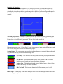
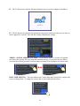
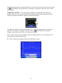
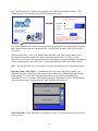
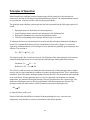
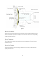
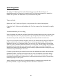
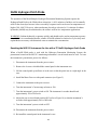
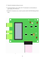
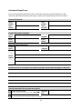
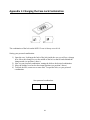
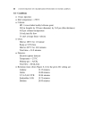
1
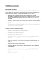
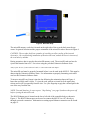
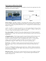
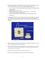
MS3112 Hydrogen Penetration Monitoring System Metal Samples Company A Division of Alabama Specialty Products, Inc. 152 Metal Samples Rd., Munford, AL 36268 Phone: (256) 358-4202 Fax: (256) 358-4515 E-mail: [email protected] Internet: www.metalsamples.com . Table of Contents System Design Features ................................................................................................................................ 1 Installation Instructions ................................................................................................................................ 3 Receiving the Instrument .................................................................................................................... 3 Verifying that the Instrument Operates Properly ............................................................................... 3 Probe Cable Verification ..................................................................................................................... 4 Instrument Installation ....................................................................................................................... 4 Hardware Overview ............................................................................................................................ 5 Probe Location .................................................................................................................................. 15 Probe Installation .............................................................................................................................. 15 Probe Removal .................................................................................................................................. 19 System Operation ....................................................................................................................................... 20 Operating Procedures ....................................................................................................................... 20 Selecting the Current Range ............................................................................................................. 20 Technical Specifications .............................................................................................................................. 21 MS3112 Hydrogen Patch Instrument ............................................................................................... 21 HYY00330100 Hydrogen Patch Probe ............................................................................................... 21 Standard Accessories .................................................................................................................................. 22 Principles of Operation ............................................................................................................................... 23 Operating Hints ........................................................................................................................................... 26 NaOH Hydrogen Patch Probe ..................................................................................................................... 28 Resetting the MS3112 Instrument for Use with a 1% NaOH Hydrogen Patch Probe ....................... 28 Service & Warranty Information................................................................................................................. 30 Warranty ........................................................................................................................................... 30 Obtaining Service and Returning the Instrument for Repair ............................................................ 30 Instrument Repair Form .................................................................................................................... 31 Appendix 1: Changing the Case Lock Combination .................................................................................... 32 . System Design Features The Metal Samples’ Hydrogen Penetration Monitoring System™ has been developed by advanced scientific research of electro-chemical conditions inherent in the corrosion process. The knowledge gained in this research laid the ground work for the engineering of the two main components of the system: the Hydrogen Patch Probe Instrument (MS3112) and the specially designed Hydrogen Patch Probe™ (HYY00330100). Figure 1. MS3112 Hydrogen Penetration Monitoring Instrument The Hydrogen Patch Probe features a sensing cell that does not require a hole to be cut in the pipe or vessel. The cell simply straps onto the pipe to be monitored. This feature provides the following advantages over conventional hydrogen probes: 1. Simple to apply 2. Easy to relocate 3. Corrosion is measured on the natural I.D., no unnatural flow or metallurgical conditions are introduced. Hydrogen Penetration Monitoring System™ and Hydrogen Patch Probe™ are trademarks of Metal Samples. 1 Since the instrument/probe is measuring the hydrogen penetration rate, the user gets fast response to changes in his system. Significant changes can be seen in less than two hours. This method for gathering data contrasts to the customary daily or weekly readings available with conventional hydrogen probes. The instrument instantaneously measures and records penetration current from a low of 10 microamps (full scale) to a high of 5000 microamps (full scale). The digital recorder stores years of data utilizing a high capacity microSD card. Figure 2. Digital Recorder 2 Installation Instructions Receiving the Instrument The purchaser should check the instrument for damage when it is first received. If there is obvious damage to the shipping carton, request that the responsible carrier’s agent be present when the instrument is unpacked. To unpack the instrument, proceed as follows: 1. Remove the MS3112 instrument from the carton. In addition to the recording instrument, the carton should contain a plastic bag of standard accessories. The carton may also contain probes and electrodes, if these were ordered at the same time as the instrument. 2. Examine the instrument for any dents, scratches, broken connectors, or other mechanical damage. 3. Open the plastic bag containing the standard accessories. Match the contents against the standard accessories parts list on page 22. Verifying the Instrument Works Properly 1. Open the lid of the aluminum case housing the MS3112. 2. Familiarize yourself with the control panel. 3. Familiarize yourself with Meter Prover. 4. Install Meter Prover by plugging into probe connector (see Figure 5) at the side of the instrument. 5. Turn Power Switch to Off. (Power Switch is located at the side of the instrument - see Figure 5.) 6. Turn current range selector to 500 microamps. 7. Plug female end to AC power cord into AC input receptacle (see Figure 5) at the side of the instrument. 8. For AC operation, plug male end of cord into any grounded 100-240VAC, 50-60 Hz outlet. 9. Turn Power Switch to On. 3 10. Check results: a. On the digital recorder, a correct reading is approximately 50% of scale. b. If these are the results, the instrument is working. Proceed with step 12. c. If these are not the results, proceed with step 11. 11. Recheck all switch positions and electrical connections. If correct results are still not obtained, contact Metal Samples. 12. Turn power switch to off. 13. Detach Meter Prover. Probe Cable Verification 14. Install Meter Prover into female end of cable, and male end of cable into the connector (see Figure 5) at the side of the instrument. 15. Repeat steps 5 through 13. Instrument Installation 1. Thoroughly read instructions before handling equipment. 2. Find a location to install the instrument where it is not exposed to direct sunlight and/or rain (preferably in a weatherproof housing). 3. Open the lid of the aluminum case. 4. Familiarize yourself with the control panel. 5. Determine the required length of probe cable from instrument to probe. This cable is purchased separately from the instrument. 6. If the performance verification has been completed, proceed with step 7. If not, complete the verification at this time. 7. Verify the instrument control switches. a. Turn power switch to off. b. Turn current Range Selector to 5000 microamps. 8. Complete probe installation procedures. 4 Hardware Overview All operation of the MS3112 is performed on the front panel using the Current range switch and the digital recorder. The functions of each are described below. Current range switch - The Current range switch is used to set the range of the probe measurement circuit in microAmps (µA.) This will set the maximum current that can be measured within the Hydrogen Patch Probe, and sets the scale for the graph on the main display. Figure 3. Current Range Switch Recorder – The MS3112 recorder is located on the front panel just above the Current range switch. The recorder consists of a backlit color touchscreen LCD display, four function keys, and an Escape (ESC) key. Aside from the Current range setting, all other MS3112 functions are managed using the touchscreen controls and the function keys. CAUTION: The recorder touchscreen can be operated using a fingertip, stylus, or other soft blunt object. However, you should never use sharp or metallic objects as they may damage the screen, nor should you use marking products such as pen, pencil, or marker tips. The recorder also offers two ports for accessing stored data; a microSD memory card slot, and an RJ-45 Ethernet port. 5 Figure 4. Recorder Body The microSD memory card slot is located on the right side of the recorder body near the top corner. Its general location and the proper orientation of the microSD card are shown in Figure 4. CAUTION: The recorder body has a number of vent holes to allow cooling of the internal electronics. Be careful during installation of the microSD card, and do not insert it into one of the vent holes by mistake. During operation, data is stored to the microSD memory card. The microSD card can later be ejected and inserted into a PC* for review using the provided Unitronics Software Suite. *May require the use of a microSD card reader, or a microSD to SD card adapter. The microSD card must be properly formatted before it can be used in the MS3112. This must be done using the Unitronics Software Suite. For information on properly formatting a microSD card see the Unitronics Software Suite. To insert a microSD card, insert it into the slot following the orientation shown in Figure 4. Insert the card fully until it clicks. To eject the card, push in on it until it clicks again, then release and it will eject partially from the slot. Use your fingertips to grip the card and pull it the rest of the way from the slot. NOTE: To avoid data loss, be sure to press “Stop Saving” (see page 9) and turn the power off before ejecting the microSD card. The RJ-45 Ethernet port is located on the lower left side of the controller body as shown in Figure 4. The RJ-45 Ethernet port can be used to connect the MS3112 to a PC directly or through a network connection. Information on setting up an Ethernet connection can be found on page 12. 6 Probe Connector and Power Entry Module The MS3112 probe connector and power entry module are located on the right-hand side of the instrument case as shown in Figure 5. AC Input Receptacle Power Switch Fuse Drawer Probe Connector Power Entry Module Figure 5. Figure 6. Probe Connector - The MS3112 utilizes a 5-pin female probe connector which is intended for use with a standard Metal Samples Hydrogen Patch Probe* and 5-pin probe extension cable. It is also used to connect the provided Meter Prover (see “Verifying that the Instrument Operates Properly” on page 3). *NOTE: The MS3112 is designed specifically for use with the Metal Samples Hydrogen Patch Probe. No other type of probe should be connected to the MS3112. Doing so could result in erroneous readings, and could damage the MS3112 instrument. Power Entry Module – The MS3112 Power Entry Module houses the AC input receptacle for connection of the AC power cord, the fuse drawer, and the main power switch, each of which are detailed below. AC Input Receptacle – The AC input receptacle accepts the female end of the AC power cord. The MS3112 is provided with a North America type power cord. However, the AC input receptacle accepts any standard AC power cord utilizing an IEC 60320 C-13 connector type. Voltage, current, and frequency ratings for the MS3112 are listed under “Technical Specifications” on page 21. NOTE: The power cable must be a grounding type. Fuse Drawer – The MS3112 is fused to protect the instrument from damage in the event of a fault or power surge. The fuse is located in the fuse drawer of the power entry module (see Figure 5). The fuse is a 5x20mm glass cartridge type fuse rated at 0.1A / 250VAC. Replace only with the same time fuse. Installing a fuse with a higher rating could result in damage to the instrument or an unsafe operating condition. Main Power Switch – The main power switch is located in the power entry module (see Figure 5). This is used to turn the instrument on and off. The green indicator light will illuminate to indicate when power is on. 7 Controls and Interface System initialization – When the MS3112 is first powered on it will momentarily show the startup screen, after which it will proceed to the main display and begin taking readings. The main display screen shows the data graph along with a number of status messages and controls. The illustration below shows the main startup screen and details the various messages and controls. MicroSD Card Status – The MS3112 checks to make sure a microSD card is present for data storage. The SD status message box along the bottom of the main display will indicate “SD Exist” when a microSD card is present, or “SD not Exist” when one is not. If the status message reads “SD not Exist” then it is necessary to insert a microSD memory card into the slot, being sure to follow the instructions page 6. System Status – The system status message box indicates the current status of the recorder and any problems that may occur. Possible messages are: Sys. Okay – This indicates that the system is working properly and that there are no current errors. RAM Error – This indicates that there is some problem with the internal RAM memory. Consult the factory for further assistance. Battery Low – This indicates that the internal backup battery voltage is low. Consult the factory for further assistance. SD Card Full – This indicates that microSD flash memory card is full. Data Graph – The majority of the main display is dedicated to the data graph which shows the recent reading history. 8 It is important to note that the vertical scale of the graph is percentage. The actual magnitude of the vertical scale depends on the setting of the Current range switch. For example, if the Current range switch is set to 200 µA, then the vertical scale of the graph is equivalent to 0 to 200 µA. Present Value – The present reading value is displayed in the lower right corner of the screen. It is important to note that this value is a percentage, and its absolute value depends on the setting of the Current range switch. For example, if the present value is 58.25% as shown above, and the Current range switch is 200 µA, then the actual value would be: Reading = 58.25% * 200 µA = 116.5 µA Start Saving / Stop Saving –The button in the lower left corner of the main display is used to toggle data logging on or off. Logging is off by default* so the button will display the message “Start Saving”. Press the “Start Saving” button to begin saving data. The unit will begin data logging, and the button will change to “Stop Saving” to indicate that data logging is in progress. *NOTE: On some occasions the button may display “Stop Saving” immediately upon startup, indicating that the unit is already logging data. If this happens, an error has occurred and the unit is giving a false indication. In this case press “Stop Saving” then press “Start Saving” to ensure that the unit begins logging data. Recorded data is written to a log file on the memory card. The log file remains open as long as the unit is recording. The log file is not closed until the user presses “Stop Saving”. This stops the data logging process and closes the log file, making it viewable on a PC using the Unitronics Software Suite. If the unit is powered down without the user pressing “Stop Saving”, the log file will not be properly closed and any data in the active log file will be lost. 9 Press “Stop Saving” at any time to stop data logging and properly close the active log file. The button will change back to “Start Saving”. If data saving is restarted, new data will either append to the existing data file, or overwrite the existing data file depending on the setting in the “TREND – SD File Append” option (see page 11). Toggle grid lines – Pressing the ‘G’ button on the left side of the screen will toggle the grid lines of the data graph on and off. Manual scroll – Pressing the ‘M’ button on the left side of the screen will bring up the manual scroll buttons, allowing you to scroll back and forth through the recent data history. When you are done, press the ‘M’ button again to hide the manual scroll buttons and return to “Run” mode. Function and Escape (ESC) Keys – Located below the touchscreen LCD display are function keys F1 through F4 and the Escape (ESC) key. These keys are used to enter and exit the additional control screens of the MS3112 as explained below. 10 F1 - The F1 function key displays the Metal Samples logo screen and company web address. F2 – The F2 function key displays the instrument setup screen which provides access to the save mode (append or overwrite), time and date settings, and Ethernet settings. TREND – SD FILE APPEND (Save Mode) – By default the MS3112 recorder will append new data to the existing file if you stop and restart data saving. If you prefer for new data to overwrite the old data, press the Overwrite button to change from Append to Overwrite mode. REAL TIME SETTING – This area indicates the Current Date and Current Time, and provides access to change them. To change the current date or time touch the desired box. 11 This will open the numeric keypad and allow the new date or time to be entered. Press the return key when finished to accept and enter your changes, or press the escape (ESC) key to abort your changes. ETHERNET SETTING – This area displays the Ethernet settings and allows them to be changed. Here you can view and change the IP Address (in IPv4 format), Subnet Mask, and Gateway (note that each address segment is updated individually.) To change any of these values touch the desired box. This will open the numeric keypad and allow the new values to be entered. Press the return key when finished to accept your changes, or press the escape (ESC) key to abort your changes. Once you have made all of your changes, press the Update button to save your changes to the system memory and make them active. F3 – The F3 function key displays the Review Data History screen. 12 F4 - The F4 function key displays the company street address and telephone number. This screen also provides a button to open the SD management screen. The SD management screen gives several status messages about the microSD memory card and has a button to delete the raw data backup file. Use this function when a card is full to easily clear space. This screen also has a “safe eject” button for the microSD card. This ensures that all writeoperations are complete and that it is safe to eject the microSD card. To safely eject the microSD card, first press “Stop Saving” from the main display to stop data logging, then proceed to this screen and press “Eject SD Card.” After that the microSD card can be safely ejected. ESC – The Escape (ESC) key exits from the selected screen and returns to main display screen. Recorder Setup (“Info Mode”) – In addition to the setup screen listed above, there is an additional setup screen which provides access to the touchscreen calibration and other factory setup options. To access this screen, touch anywhere on the touchscreen and hold for approximately five (5) seconds. This should bring up the “Info Mode” screen. The Info Mode screen has two options: “Enter Info Mode” and “Calibrate Touchscreen.” Enter Info Mode - Enter Info Mode is for factory use only. It is password protected and is not for user access. 13 Calibrate Touchscreen - Calibrate Touchscreen is used to perform a calibration of the touchscreen’s X and Y positional accuracy. Use this function if you find that the touch detection of the screen has become inaccurate. When the calibration process begins, the screen will go black with a single calibration marker displayed near the upper-left corner. Touch the center of the calibration mark with your fingertip or a stylus, trying to be as accurate as possible. After touching the calibration mark it will move to a new position on the screen. Touch it again each time it moves until the instrument returns to the “Info Mode” screen. At this point the touchscreen calibration is complete, and the positional accuracy should be more precise. PC Software The MS3112 utilizes a Unitronics controller, and is provided with the Unitronics Software Suite which provides tools for data review, remote access via the ethernet connection, memory card formatting, and other useful features. The software is provided on CD-ROM disc. To install the software, insert the disc into your PC’s CD-ROM drive and follow the on-screen instructions. Documentation on using the Unitronics Software Suite is provided on the CD-ROM. Maintenance and Safety Touchscreen The touchscreen should be cleaned periodically to ensure good response and provide good visibility. Clean the touchscreen using a soft damp cloth. Do not use abrasives or solvents. Use only your fingertip or an appropriate stylus to operate the touchscreen. Do not use sharp or metal objects as this could damage the screen. Do not use marking objects such as pencil, pen, or marker tips. Vent holes The recorder vent holes should be kept clean and free of dust to ensure proper ventilation and cooling of the internal electronics. Never block or cover the vent holes. This could cause the recorder to overheat. Never insert foreign objects into the vent holes. This could damage the internal components and cause the recorder to fail. Clean periodically Electrical connections Ensure that a properly grounded electrical outlet is used. Ensure that the supply voltage does not exceed the rated supply voltage maximum. Ensure that the electrical cord is a grounding type. Ensure that the electrical cord is in good condition and that there are no breaks in the insulation or internal wiring. 14 Probe Location Locate the HPP at a pipe or vessel where hydrogen permeation is suspected. Locate the probe as close as possible to the corroding areas of the pipe or vessel. Probe Installation Probe installation is generally a two-man operation. Needed accessories not supplied with the HPP are: screwdriver (flathead) sandpaper fine file coarse file 96% sulfuric acid (H2SO4) acid disposal container clean rag squirt bottle containing at least one quart of clean water CAUTION: If the probe is to be installed at a remote location where water is not quickly available, carry to the installation site additional clean water to be used in case acid is splashed on the skin or into the eyes. To install the HPP, complete the following procedures. Refer to Figures 7 and 8 for location and orientation of probe components. 1. The HPP must be fitted to the curvature of the pipe or vessel at which the probe is to be installed. To fit the HPP, complete the appropriate procedure: Fitting the HPP to Vessel Curvature The two 3/8" diameter holes located on the probe’s side extensions (see Figure 7) permit the probe to be mounted on threaded studs when the diameter of the vessel exceeds that of the largest available band clamps. Fitting the HPP to Pipe Curvature a. Determine the curvature of the pipe. b. For pipes greater than 40 inches in diameter, use the pipe adapter as is (flat face). c. For pipes less than 40 inches in diameter, machine the probe adapter to the correct curvature. Increase the depth of the curvature 3/8” to accommodate the Teflon® gasket liner. a. Weld two studs to the surface of the vessel. b. After completing steps 2 to 9, slip the HPP onto the studs, ensuring that the probe remains centered over the foil. d. Check for a good f it with the Teflon®/ Viton® gasket assembly mounted on the probe adapter by holding the adapter against the pipe. c. Secure the probe. d. Complete steps 11 to 20. Teflon® is a registered trademark of DuPont. Viton® is a registered trademark of DuPont Dow Elastomers. 15 2. Prepare the metal surface to which the HPP is to be mounted. The metal surface must be clean, smooth and burrless. Clean to bare steel an area approximately 3" x 3". a. Use a coarse file to remove any rust or organic film from the metal surface. Do not create low spots by excessive filing. If a low spot develops, move to an adjacent area and begin again. b. Smooth rough spots with a fine file. c. Smooth the metal surface to a fine finish with sandpaper. A smooth finish is necessary to avoid tearing the palladium foil. d. Use water and a clean rag to clean the metal surface of filings and dust before applying wax. 3. If mounting the HPP on a pipe, loosely loop four band clamps around the pipe. Separate the clamps into two sets. In each set, position the clasp of the first clamp opposite the clasp of the second clamp so that the bands will pull in opposite directions when they are tightened. Figure 7. Disassembled Hydrogen Patch Probe 4. Rub the cleaned surface of the metal with the wax bar supplied with the HPP or with one of the recommended wax types listed on page 19. 5. Gently bend the palladium foil to the approximate curvature of the pipe or vessel. Place the foil over the wax, positioning the soldered wire/foil joint at the top so that it faces away from the wax (see Figure 8). 6. Place the Teflon® liner inside the Viton® gasket (see Figure 8). 7. Place the probe adapter inside the main body of the probe (see Figure 8). 16 8. Center the Teflon®/Viton® gasket assembly over the palladium foil. Hold the gasket assembly in place. 9. Position the probe adapter/main body assembly over the Teflon®/Viton® gasket assembly so that the probe adapter holds the gasket assembly in place and the probe’s vent (see Figure 7) points up. 10. Position the band clamps over the probe’s side extensions and tighten the clamps. Tighten clamps only enough to prevent the probe from leaking. Ensure that the probe remains centered over the foil. The four corners of the foil should be equally visible. 11. Remove the probe’s vent and fill the probe with water. 12. Check for leaks. Wait 5 to 10 minutes. Again check for leaks. Water drops should not be present. 13. If a leak is indicated, tighten band clamps and/or check for probe misalignment. The probe may have to be removed and then reinstalled to eliminate leaks. 14. If no leaks are evident, use the syringe to remove all water from the probe. Remove water carefully to avoid damaging the foil. Any excess water left in the probe will dilute the acid and may cause corrosion of the probe’s internal components. 15. Fill the probe with commercially available 96% sulfuric acid. Do not overfill the probe. CAUTION: Sulfuric acid is very corrosive to the skin; therefore, avoid splashing acid. If skin or eyes accidentally come into contact with the acid, immediately flush the affected area with water. 16. Reinstall the vent into the probe body. 17. Properly dispose of any acid remaining in the syringe. Rinse probe and syringe in clean water. 18. Check for leaks. Acid leakage will prevent the instrument from operating properly. If leaks are evident, remove the probe following procedures below for Probe Removal. Reinstall the probe if desired. 19. If no leaks are evident, allow the probe to equilibrate for 10 hours. 20. Connect the female end of the probe cable to the HPP’s probe connector (see Figure 8). The HPP is now operational. Teflon® is a registered trademark of DuPont. 17 Figure 8. Hydrogen Patch Probe Mounting Assembly 18 Probe Removal 1. Disconnect the female end of the probe cable from the HPP’s probe connector. 2. Very carefully, remove the probe’s vent assembly. 3. Use the syringe to remove the acid from the probe through the vent port. Dispose of the acid in an acid disposal container. 4. Use the syringe to rinse the probe’s internal components by adding and removing water several times. 5. Unplug the palladium foil wire from the probe. 6. Loosen the band clamps and remove the probe being careful not to damage the palladium foil. 7. Clean and store the probe. Metal Temperature at Time of Application 100°F to 150°F 50°F to 120°F Recommended Wax Bareco Ultraplex Amber (supplied with the HPP) Dimestore candle wax Table 1: Recommended Wax Types 19 System Operation Operating Procedures Operating procedures for the MS3112 are very simple. Once the current range selector is correctly adjusted, the instrument operates automatically. The data is time and date stamped. CAUTION: Periodically conduct a verification of instrument operation with Meter Prover (refer to page 3). If the instrument does not test properly, disconnect the instrument and contact Metal Samples for assistance. Selecting the Current Range 1. Check the recorder value. 2. If the value is too low (less than 25% scale), move the selector to the next lowest range. 3. Repeat steps 1 and 2 until there is a stable reading at approximately 50% of scale. Note: The probe should be installed for at least 10 hours before it is connected to instrument. If the probe is connected before equilibrium is obtained, erroneous instrument readings will result. 20 Technical Specifications Model MS3112 - Hydrogen Penetration Monitoring System (Ordering # IN3112) Physical Data Instrument Weight: Total Weight w/ Accessories: Instrument Dimensions: 6.6 lb. (3 Kg) 7.6 lb. (3.45 Kg) 5.25"H x 12.25"W x 10.5"D (13.34cm x 31.12cm x 26.67cm*) *Including handle and feet. Performance Data Measurement Type: Range: Hydrogen Penetration Switch Selectable Ranges from 10µA to 5000µA Electrical Data Power Requirements: Output Specifications: 100-240VAC, 50/60 Hz > 5 years of data storage (depends on configuration) Special Features • • • • • Integrated digital recorder Data stored to microSD flash memory card On-screen data review Switch selectable range Portable Included Accessory Items Meter Prover, AC Power Cable, Operation Manual, microSD Flash Card Optional Accessory Items (sold separately) Hydrogen Patch Probe - Part # HYY00330100 Palladium Foil - Part # PS5576718 Instrument-to-Probe Cable - Part # PS5547LLL (LLL= length in feet, specify required length) Hydrogen Patch Probe™ (HYY00330100) Materials of Construction: Viton®, Polypropylene, Teflon®, Kalrez® Reference & Auxiliary Electrodes: Hastelloy C-276 Working Electrode: Palladium foil (sold separately) Electrolyte: 96% H2SO4 - cell volume 40 ml Temperature Range: -10°F to +290°F Hydrogen Penetration Monitoring System™ and Hydrogen Patch Probe™ are trademarks of Metal Samples. Teflon® is a registered trademark of Dupont. Viton® and Kalrez® are registered trademarks of DuPont Dow Elastomers. 21 Standard Accessories Instrument Accessories Quantity 1 1 1 1 1 Description Meter Prover AC Power Cord .1 amp fuse slo blo Software CD 2GB microSD Flash Memory Card Probe Accessories Quantity 4 1 1 1 1 oz. Description Steel mounting hose clamps - 4" dia. Hypodermic Syringe 50cc Needle - 13 gauge Viton® Gasket Wax - High Temperature 22 Principles of Operation Metal Samples has combined electrical engineering with the principles of electrochemical corrosion to develop the Hydrogen Penetration Monitoring System. The instrumentation consists of a potentiostat, a current recorder, and a hydrogen patch probe. The principle upon which the system operates has been separated into the following sequence of events: 1. 2. 3. 4. Hydrogen atoms are formed by the corrosion process. Some Hydrogen atoms enter the steel and travel to the Palladium foil. Hydrogen is quantitatively reacted at the Palladium surface. Current corresponding to the hydrogen diffusion rate is recorded. To illustrate the theory of electrochemical corrosion and the subsequent formation of hydrogen atoms, let’s consider the behavior of iron in hydrochloric acid (refer to Figure 9). Iron reacts vigorously with hydrochloric acid. Hydrogen evolves and the iron gradually goes completely into solution. The reaction is: Fe + 2HCl FeCl2 + H2 The solution in the above reaction is ionized. By definition of the redox principle, iron has been oxidized and hydrogen ions have been reduced (each hydrogen ion has gained an electron). Oxidation: Fe Fe++ + 2e + Reduction: 2H + 2e 2H The velocity of the corrosion rate determines the formation rate of the hydrogen atoms (a highly reactive specie) which immediately combine to produce hydrogen molecules. This is important to remember. Not all the atomic hydrogen produced enters the steel. The amount that enters depends on several factors. For any particular piece of steel in a particular environment at a constant temperature, the amount of hydrogen entering is directly proportional to the corrosion rate. The formation of hydrogen atoms is directly proportional to the deterioration rate of metal. The hydrogen atoms can either produce relatively harmless molecules (Hydrogen Gas). 2H0 H2 or enter the lattice of the steel. Factors which affect the diffusion of atomic hydrogen through steel are: corrosion rate; temperature; steel thickness; corrosive environment; and catalyst poisons. 23 Figure 9. Effect of Corrosion Rate Not all corrosion generated atomic hydrogen enters the steel but the amount that does enter is directly related to the corrosion rate. Changes in corrosion rate will result in a corresponding change in hydrogen diffusion. Effect of Temperature With all other factors constant, increased process system temperature will cause increased hydrogen diffusion. Effect of Steel Thickness Increased steel thickness decreases hydrogen diffusion as detected by the HYY00330100 Hydrogen Patch ProbeTM. 24 Effect of Poison In sweet systems (not containing sulfide), the percentage of corrosion generated hydrogen that enters the steel is a fraction of that which enters in sour systems (containing sulfide). One system which efficiently promotes hydrogen diffusion through steel is the NH3/H2S/CN system. The partial pressure of hydrogen gas in a system does not influence hydrogen permeation rates, unless temperatures are high enough to cause thermal dissociation of the hydrogen gas. Also the presence of catalytic metals may decrease the temperatures at which the thermal dissociation of hydrogen gas becomes significant. Principles of MS3112 Hydrogen Penetration Monitoring System Operation The hydrogen monitoring process begins when hydrogen atoms permeate the HYY00330100 Hydrogen Patch Probe’s (HPP) special palladium foil sensing cell. Palladium is a unique metal that is transparent to hydrogen atoms. As shown in Figure 9, the metallic foil permits rapid diffusion of hydrogen atoms through the foil to the palladium surface in contact with the HPP and its internal electrolyte (sulfuric acid) reservoir. The palladium foil also acts as a working or tet electrode during HPP operation. The operation of the Hydrogen Patch Probe is based on a simple electrochemical reaction. Hydrogen atoms are quantatively oxidized to hydrogen ions at the surface of an electrode (the palladium foil) which is maintained at a constant potential. The MS3112 Hydrogen Patch Probe Instrument, preset at the factory at a potential relative to the HPP’s internal reference electrode, supplies current to oxidize any atomic hydrogen (H0) appearing on the surface of the palladium foil that is in contact with the acid electrolyte solution. The current required for oxidation is a direct measure of the hydrogen diffusing into the HPP. The oxidation reaction is: 2H0 2e + 2H+ The hydrogen ions move through the acid electrolyte to the auxiliary electrode. At the auxiliary electrode, hydrogen ions are reduced to hydrogen gas. The reduction reaction is: 2H+ + 2e H2 Operation of the MS3112 Hydrogen Penetration Monitoring System does not consume the electrolyte and the net flow through the HYY00330100 HPP is: atomic hydrogen into the probe and hydrogen gas out the probe’s vent. 25 Operating Hints The utility of the Hydrogen Penetration Monitoring System will reflect the degree of thoughtfulness and care displayed in its application. The following information is intended to enhance the operation and maintenance of your instrument and probe. To prevent leaks Replace the Viton® Gasket (see Figure 8) every time the cell is removed and replaced. Center the Viton® Gasket over the Palladium foil. The four corners of the foils should be equally visible. To understand what you’re reading Note all pertinent data with time and dates. Identify the monitored process stream or system. Note stream composition, flow rate, pipe temperature, type and quantity of treatment chemicals, line shut down time periods, and any other condition potentionally related to corrosion rate. Log-in every occurrence with time and date, where (A) the instrument is de-energized while the probe is operationally connected; or (B) the probe is made operational within 10 hours of its installation. In case (A), a hydrogen build-up occurs in the cell if the instrument is de-energized while the probe is attached. When the instrument is re-energized, current readings may be higher than normal and also may take some time to reach a steady state. In case (B), if the probe is installed and connected to the instrument before reaching equilibrium then the readings may vary at random, rising and falling for some time. Construct a graph showing the relation between time (the independent variable) and current (the dependent variable). The time scale intervals may be set as best befits the needs of the analyst. Recommended are graphs showing a 30 day time span. Current scale intervals require careful reviewing of recorded currents to determine a useful measurement range while at the same time, monitoring changes in the system. Analyze changes (rises and falls) of the plotted readings by comparing with compiled data previously detailed, as regards matching the times and dates of occurrences. 26 The following questions and answers regarding maintenance are provided to help maintain good performance by the system. How long does the Palladium foil last? The foil should have a life span approximating those shown in Table #2. The Palladium foil is critical to the cell’s operation. It must be Palladium. The critical area in determining hydrogen throughput is the area of wax-to Palladium contact. Good contact must be assured between the Palladium, test electrode and the monitoring circuit. Temperature of Application 100°F 140°F 180°F Foil Thickness 10 mil 10 mil 10 mil Approximate Useful Life 2 years 2 years 6 months Why 96% Acid? In terms of conductivity and evaporation, 90% would be best. But since the electrolyte is hygroscopic and some water vapor will probably breathe into the probe, it is best to start with 96%. Why a vent assembly on the probe? The check valve or other construction in the filler plug is important for two reasons. First, the hydroscopic nature of the electrolyte can cause dilution and overflow. Second, in normal operation of the cell, hydrogen gas is evolved at the auxiliary electrode; this pressure must be relieved to prevent electrolyte being forced past the Viton® gasket. Fortunately, a small hydrogen escape path will prevent pressure buildup. Does the acid deteriorate? Yes. The degradation force is acid attack of the Viton®. Contact is minimized by the cell design, especially with Teflon® gasket “liners”, but the acid still becomes blackened. Cell operation is not effected by Viton® degradation. When does the acid need changing? As a precaution, it is recommended that the electrolyte be removed, the cell rinsed with water, and electrolyte replaced at intervals of ½ the expected life of the foil (refer to Table #2). This can be done with the filling syringe supplied with the HPP and a water squirt bottle for spillage rinsing. Always ensure that the syringe needle does-not damage the Palladium foil. When do the electrodes need replacing? Check the electrodes whenever the Palladium foil is inspected. If electrodes show deterioration, they need changing. 27 NaOH Hydrogen Patch Probe The operation of the Metal Samples Hydrogen Penetration Monitoring System requires the Hydrogen Patch Probe to be filled with an electrolyte. A 96% solution of sulfuric acid is normally used for the electrolyte because it does not readily evaporate and it can be used at temperatures as high as 300 - 400°F. However, when an alternate electrolyte is desired, a 1% solution of sodium hydroxide (NaOH) may be substituted to, the sulfuric acid for low temperature applications. WARNING: Sodium hydroxide evaporates quickly and should not be used at temperatures greater than 150°F. It is recommended that the volume of NaOH solution be checked every few days and replenished as necessary with deionized water to maintain the concentration. Resetting the MS3112 Instrument for Use with a 1% NaOH Hydrogen Patch Probe When a NaOH filled probe is used with the Hydrogen Penetration Monitoring System, the potentiostat located on the MS3112 monitoring instrument’s circuit board must be reset. To reset the instrument’s potentiostat, proceed as follows: 1. Disconnect the instrument from the power source. 2. Remove the 4 screws which hold the control panel in the instrument case. 3. Lift the control panel up and brace it in the case so that the panel sets at a right angle to the case. 4. Install the Meter Prover at side panel connector (see Figure 5). 5. Connect the instrument to the power source. 6. Turn the instrument’s Current range selector to 500. 7. Turn the instrument’s power switch to ON. The instrument’s recorder should read approximately 50% of full scale. 8. Adjust the pot at circuit board position R12 (refer to Figure 10) so that the instrument’s recorder reads approximately 40% of full scale. 9. Turn the instrument’s power switch to OFF. 10. Disconnect the instrument from the power source. 11. Re-install the control panel in the instrument’s case. 28 12. Connect the instrument to the power source. 13. Turn the instrument’s power switch to ON. The instrument’s recorder should read approximately 40% of full scale. 14. The MS3112 instrument is now ready for operation with a NaOH filled Hydrogen Patch Probe. R2 R12 R14 Figure 10. MS3112 Circuit Board, Position R12 29 Service & Warranty Information Warranty Metal Samples warrants that any part of the MS3112 and accessories which proves to be defective in material or workmanship within one year of the date of original shipment to Purchaser will be repaired or replaced, at Metal Samples option, free of charge. This warranty does not cover (1) probe assemblies, (2) items expendable in nature, or (3) items subject to damage from normal wear, misuse or abuse, or failure to follow use and care instructions. All damaged items are to be shipped at Purchaser’s expense to and from Metal Samples which shall have the right to final determination as to the existence and cause of a defect. The foregoing shall constitute the sole and exclusive remedy of any purchaser of Metal Samples products for breach of warranty and IS EXCLUSIVE AND IN LIEU OF ALL OTHER WARRANTIES, EXPRESSED, IMPLIED OR STATUTORY, INCLUDING THE IMPLIED WARRANTIES OR MERCHANTABILITY AND FITNESS. IN NO EVENT SHALL METAL SAMPLES BE LIABLE FOR SPECIAL OR CONSEQUENTIAL DAMAGES, OR FOR ANY DELAY IN THE PERFORMANCE OF THIS WARRANTY DUE TO CAUSES BEYOND ITS CONTROL. The technical information and suggestions contained herein are believed to be reliable, but they are not to be construed as warranties since conditions of use are beyond our control. Obtaining Service and Returning the Instrument for Repair If you experience problems with your instrument please contact the factory at 256‐358‐4202 and ask for customer support for instrumentation. Our customer support department will assist you in troubleshooting your instrument. Most issues can be resolved over the phone, but in some cases it may be necessary to return your instrument for further evaluation and repair. In this case, please obtain a Return Materials Authorization (RMA) number from the sales person or support technician. This RMA number will ensure that your instrument is routed to the correct department when it is received at the factory. After receipt of an RMA number you may pack your instrument for return. Be sure to pack your instrument in a sturdy box and to pad it sufficiently to avoid damage during transit. Also be sure to complete the “Instrument Repair Form” on the next page and include a copy with your repair. This will ensure that the repair department has sufficient information regarding the problems you are experiencing with your instrument, as well as the billing, contact, and return shipping details for the repair. Once you have obtained an RMA number, completed the “Instrument Repair Form”, and packed your instrument securely, please ship it prepaid to the following address: Metal Samples 152 Metal Samples Road Munford, AL 36268 ATTN: RMA# _ _ _ _ _ NOTE: Be sure to list your RMA number in the attention line (shown as blanks in the example above.) 30 Instrument Repair Form This form may be photocopied for use when returning an instrument to Metal Samples for repair. Please fill in all known information and enclose a copy of the completed form with the instrument. General Information Model Number RMA Number Serial Number Date of Purchase* *If known. Contact Information for Repair Contact Name Company Phone Number E‐mail Address Return Shipping Information Recipient Name* Return Address Company* *If different than above. Reason for Return. (Provide as much detail as possible. Attach additional pages if required.) Invoice Instructions (For non‐warranty repairs) Invoice me for the repair (Requires an open account with Metal samples.) Contact me for credit card information Reference PO# (For security purposes, do not list credit card information on this form..) 31 Appendix 1: Changing the Case Lock Combination The combination of the lock on the MS3112 case is factory set at 0-0-0. Setting your personal combination: 1) Open the case. Looking at the back of the lock inside the case you will see a change lever. Move this change lever to the middle of the lock so that it hooks behind the change notch (see position 1 above). 2) Now set your personal combination, turning the dials to the desired combination. 3) Move the change lever back to the normal position (see position 2 above). 4) To block the lock, rotate one or more dials. To open the lock, set your personal combination. Your personal combination: 32