1
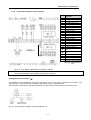
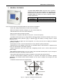
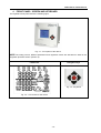
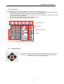
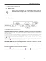
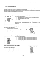
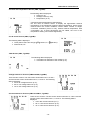
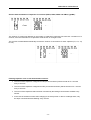
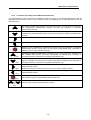
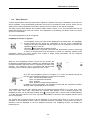
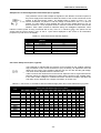
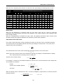
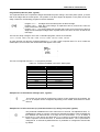
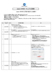
POWER FACTOR REGULATOR
PFCL Elite 6/PFCL Elite 12
Instruction Manual
PFCL Elite 6 / PFCL Elite 12
-1-
PFCL Elite 6 / PFCL Elite 12
Table of contents_________________________________________________________
1
INTRODUCTION AND SAFETY TIPS ............................................................................................................... 3
1.1
CHECKS TO BE CARRIED OUT WHEN THE REGULATOR IS RECEIVED ................................................................... 3
1.2
DEFINITIONS ..................................................................................................................................................... 4
1.2.1
4-Quadrant Regulator. ................................................................................................................................ 4
1.2.2
FCP System (FAST Computerized Program). ............................................................................................. 4
1.2.3
Stages and Steps .......................................................................................................................................... 5
1.2.4
Regulation Program. ................................................................................................................................... 5
1.2.5
Plug and Play. ............................................................................................................................................. 5
1.2.6
Connection and Reconnection Time. ........................................................................................................... 5
1.2.7
Harmonics and THD ................................................................................................................................... 6
2
INSTALLATION AND START-UP ...................................................................................................................... 6
2.1
TECHNICAL FEATURES ...................................................................................................................................... 7
2.2
EQUIPMENT INSTALLATION .............................................................................................................................. 7
2.2.1
Mechanical Installation .............................................................................................................................. 7
2.2.2
Connections ................................................................................................................................................. 8
2.2.3
Cable sections and protection elements ...................................................................................................... 8
2.2.4
Connection diagrams. PFCL Elite 6/12. ..................................................................................................... 9
3
GENERAL FEATURES ....................................................................................................................................... 11
4
FRONT PANEL: SCREEN AND KEYBOARD................................................................................................. 12
4.1
4.2
5
LCD SCREEN .................................................................................................................................................. 13
NAVIGATION KEYS.......................................................................................................................................... 13
REGULATOR'S OPERATION ........................................................................................................................... 14
5.1
5.2
5.3
5.3.1
5.3.2
5.4
5.4.1
5.4.2
5.5
5.6
START-UP SCREEN .......................................................................................................................................... 14
DEVICE STATES .............................................................................................................................................. 14
MEASUREMENT SCREENS ............................................................................................................................... 15
Functions of the Keys on the Measurement Screens ................................................................................. 18
Browsing the Measurement Screens.......................................................................................................... 19
SETUP SCREENS .............................................................................................................................................. 20
Functions of the Keys in the Setup Screens ............................................................................................... 28
Browses the setup screens. ........................................................................................................................ 29
ERROR MESSAGES: ERRORS AND ALARMS .................................................................................................... 30
ALARM RELAY ............................................................................................................................................... 30
6
INTEGRATION OF PFCL ELITE IN SCADA POWER STUDIO ................................................................. 31
7
MAINTENANCE .................................................................................................................................................. 31
8
TECHNICAL SERVICE ...................................................................................................................................... 31
-2-
PFCL Elite 6 / PFCL Elite 12
1
INTRODUCTION AND SAFETY TIPS
INTERNATIONAL CAPACITORS S.A. thanks you for choosing one of the regulators from the PFCL Elite
series. These units have been built with state-of-the-art technologies, including a powerful processor that can
calculate the optimum algorithms and achieve the best correction of the cos φ.
The units comply with the EN 61010 Electrical Safety Standard, in accordance with the Low Voltage Directive
requirements (LVD 73/23/EC), as well as the EMC Directive (2004/108/EC) and are, therefore, certified for
use with the CE mark.
The purpose of this user manual is to describe the operating principles for the regulators from the PFCL Elite
series and to define the installation, start-up and operation procedures.
SAFETY
The installation and maintenance of the equipment must be performed by qualified and
authorised staff, in accordance with the national and international Standards. Any
manipulation or use of the equipment different from that specified by the manufacturer
may compromise user safety.
The main switch must be disconnected before any maintenance to be performed on the cos φ
regulation equipment. After the main switch has been disconnected, wait at least 5 minutes to make
sure that all capacitors have been discharged.
The following safety precautions must be taken into account during installation, maintenance or start-up
operations on equipment regulated with a PFCL Elite unit:
Make sure that the units have the corresponding earthing connections before they are connected. A
faulty earthing connection could lead to a faulty operation and represent the risk of electrical
discharge to the user or person handling the equipment.
The necessary precautions will be taken during maintenance operations to prevent the risk of
electrocution and electric shock. Make sure that the unit has been disconnected and wait until the
capacitors have been fully discharged before handling or operating the unit. We recommend the use
of safety goggles and gloves.
Resonance can be produced when the power factor compensation units are connected with no
loads. In this case, the voltage harmonics can be amplified, causing damage to the compensation
equipment and other equipment connected to the network.
Follow the start-up and stop procedures described in the manual to prevent damage to the unit
and/or adjacent equipment.
Always use original spare parts or components when adjusting or replacing components and follow
the corresponding procedures described in the instruction manual.
1.1
Checks to be carried out when the regulator is received
On receiving the regulator, check that:
The unit has not been damaged during transport.
The type supplied is the same as that requested. (See label on the rear, Fig. 1.1)
Check the features shown on the unit's label, to make sure that they are valid for the type of grid
where the unit will be connected. (Voltage and power supply frequency, measurement range, etc.)
Follow the instructions described in section 2, in relation to the rest of the installation and setup.
Please contact the technical-commercial service of INTERNATIONAL CAPACITORS, SA if you
detect any anomalies.
-3-
PFCL Elite 6 / PFCL Elite 12
Fig. 1.1.- Rear label of the unit
1.2
Definitions
The following definitions might be useful to understand some of the sections in this manual.
1.2.1
4-Quadrant Regulator.
The regulator is capable of performing the measurement and regulation functions when the active power is
transferred from the grid to the loads (common case in a consumer installation) or when the load is
transferred to the grid (this is the case of installations with generators that not only allow the consumption of
energy, but can also export and sell energy).
1.2.2
FCP System (FAST Computerized Program).
This system controls the connection sequence of the different stages, tending to minimise the number of
operations and matching the usage times of the different stages to achieve the determined final power
demand. The operations are carried out in such a way that, in the case of stages with an identical power, the
stage that has been disconnected the longest is connected when there is demand and the stage that has
been connected the longest is disconnected in the case of a surplus.
-4-
PFCL Elite 6 / PFCL Elite 12
1.2.3
Stages and Steps
We must explain the difference between stages and steps. In this manual, a STAGE is described as the
capacitor banks in which the power factor compensation unit is divided, which may have different power
ratings, usually in 1:1, 1:2, 1:2:4, etc. ratios.
A step is each one of the total power fractions (power of the first step) that can be regulated with the use of
stages with a different weight.
1.2.4
Regulation Program.
The power ratings of the different groups or stages usually follow certain patterns called "programs”. The
program indicates the power ratios between different stages. The most frequent programs are:
Program 1:1:1:1. All stages have the same power. For example, a 100 kvar unit with 5 steps would be
composed of 5 identical 20 kvar stages and it would be described as a (5 x 20) kvar unit.
Program 1:2:2:2. All stages after the second stage have twice as much power as the first stage. For
example, a 180 kvar unit with 5 stages would be composed of a first 20 kvar stage and 4 identical 40 kvar
stages. It could be described as a (20 + 4 x 40) kvar unit.
Program 1:2:4:4. The power of the second stage is twice as much as the first stage and all other stages
after the third stage would have four times as much power as the first stage. For example, a 300 kvar unit
with 5 stages would be composed of a first 20 kvar stage, a second 40 kvar stage and 3 identical 80 kvar
stages. It could be described as a (20 + 40 + 3 x 80) kvar unit.
Other Programs. Other programs can be used, such as 1:2:2:4, 1:2:4:8 or 1:1:2:2, etc. The meaning of the
numbers, as assumed in previous cases, shows the proportion of the powers between the first stage, which
receives a value of 1 and the next stages (2 means twice as much power, 4 means four times as much
power, etc.).
The unit can easily configure one of the 10 standard programs, which are as follows:
1:1:1:1, 1:2:2:2, 1:2:4:4, 1:2:4:8, 1:1:2:2, 1:1:2:4, 1:2:2:4, 1:2:3:3, 1:2:3:4, 1:2:3:6.
An open program can also be configured between 1:1:1:1 and 1:9:9:9 in special cases.
1.2.5
Plug and Play.
A series of parameters must be configured when a power factor regulator is installed, to make sure that it
operates correctly. Some of these parameters might be hard to know, such as, for example, the voltage
phases or the voltage corresponding to the current measured, as well as the current transformer ratio. PFCL
Elite has been designed with a smart automatic process that detects the necessary parameters, such as:
C/K: calculates the ratio of the current transformer and the power of the smallest step.
Phase: Identifies the voltage sequence and correspondence with current. In other words, it identifies
the UL1, UL2, UL3, when the current measured is IL1, IL2, IL3 and whether it is connected in the
opposite way or not.
Number of stages installed and Program: the system connects all stages in a sequence, finds out
how many stages are installed and then calculates the program, i.e., the power ratio of the
capacitors (see Section 1.2.4).
1.2.6
Connection and Reconnection Time.
Connection time Tc defines the minimum time between changes in the status of stages, i.e., between
connections and disconnections. Therefore, the configuration of this parameter has a direct impact on the
compensation speed, in other words, on the monitoring capacity after changes in load. Establish a shorter
connection time to improve the power factor correction when the load can change quickly.
However, a shorter Tc will lead to a higher number of connections per time unit, shortening the useful life of
the associated components (contacts, capacitors). To assess the number of connections, PFCL Elite uses
individual meters for each capacitor.
The reconnection time is the minimum time between the disconnection of a stage and its reconnection. This
time is required to discharge the capacitor enough to prevent an over-current in the system after it is
reconnected.
-5-
PFCL Elite 6 / PFCL Elite 12
1.2.7
Harmonics and THD
Non-linear loads, such as those in rectifiers, inverters, speed drives, kilns, etc., absorb non-sinusoidal
periodic currents from the grid. These currents are composed of a fundamental frequency component, rated
at 50 or 60 Hz, plus a series of overlapping currents, with frequencies that are multiples of the fundamental
frequency; they are defined as harmonics. The result is a deformation of the current and, as a consequence,
of the voltage, which leads to a series of associated secondary effects (overloads in conductors, machines
and automatic switches, phase offsets, interferences in electronic equipment, RCCB trips, etc.).
The level of harmonics is usually measured with the total harmonic distortion rate (THD), which is the ratio,
usually as a %, of the RMS value of the harmonic content and the value of the fundamental component.
2
INSTALLATION AND START-UP
This section contains information and warnings that the user must respect at all times to guarantee his own
safety and the safe operation of the device.
WARNING! The PFCL Elite regulators are connected to units with capacitors that remain
charged even after the voltage has been disconnected. Wait at least 5 minutes after the
equipment is disconnected, before the internal components of the equipment are handled, in
order to avoid the risk of electric shock.
Any manipulation or use of the equipment different from that specified by the
manufacturer may compromise user safety.
The power supply must be disconnected from the unit when it shows signs of deterioration or a faulty
operation. In this case, contact a qualified service representative.
The persons responsible for the installation or operation of the PFCL Elite 6 or PFCL Elite 12 regulator must
follow the common safety measures for LV or MV installations to guarantee a safe operation, depending on
the installation location. In addition, they must take into account all safety warnings stated in this instruction
manual.
-6-
PFCL Elite 6 / PFCL Elite 12
2.1
Technical features
The main features of the unit are marked on the label on the rear (see Fig. 1.1) and they are also described
in the quick guide attached. They are summarised in the following table:
Main power supply and
voltage measurement
Power supply cables
Current measurement
circuit
Leakage current
measurement circuit
Current measurement
margin
Measurement accuracy
Temperature
measurement
Consumption
Output
Cabling and output relay
protection
Alarm relay
480, 400, 230, or 110 Vac. +15 % -10 %; 50/60 Hz, (see label) Power supply: UL1UL2. Measurement UL1, UL2, UL3 and UN
Section 1.5 mm2, gl 0.5 to 2 A protection fuse
Current transformer (CT), In /5 A AC., preferably on phase L1. Min. cable section.
2.5 mm2
Nominal current of transformer secondary: I∆sec = 2 mA AC. Transformer with
ratio of 500: I∆ = 1 A AC. +20%
Current I: 0.05 ... 5 A AC (maximum overload +20%)
Leakage current I∆: 0.01 ... 1 A AC(maximum overload +20%)
Voltage and current: 1%; cos ϕ: 2% ± 1 digit
External temperature approximation. Range: 0 ... 80ºC. Accuracy: ± 3ºC
8.2 VA (empty); 9.3 VA (6 relays); 11 VA (12 relays)
Relays. Contacts for Umax. 250 Vac., 4 A AC., AC1.
Cable section 1.5 mm2, protection with circuit breaker (C curve) of 6 A or gl 6 A
fuse
Switched relay for use exclusively for the alarms
IEC 62053-23 (2003-01) Ed. 1.0
IEC 61326-1, EN61010-1, UL 508
Standards
Safety/Insulation
Category III, Class II, according to EN 61010-1
IP40 (equipment mounted, cabinet front panel)
Protection degree
IP30 (equipment not mounted) according to EN-60529
Admissible
Temperature: -20 ... +60ºC; Relative humidity: max. 95% (without condensation).
environmental conditions Max. altitude: 2000 m
Control system
FCP (a program that minimises the number of operations)
Communications
Interface: RS485.
Protocol: MODBUS.
Speed: 9600, 19200, 38400
The PFCL Elite regulator
measures and operates
in 4 quadrants according
to the attached diagram.
2.2
2.2.1
Equipment Installation
Mechanical Installation
In mechanical terms, the equipment is installed in a cabinet's front panel or in a panel. The panel fixing drill
must be drilled in compliance with DIN 43 700, (dimensions: 138+1x138+1 mm).
-7-
PFCL Elite 6 / PFCL Elite 12
2.2.2
Connections
The following points must be checked before the unit is powered:
The installation and maintenance of the equipment must be performed by qualified and
authorised staff, in accordance with the national and international Standards.
All connections must remain inside the electrical panel.
Take into account that, when the device is connected, the terminals may be hazardous to the
touch, and opening the covers or removing elements may expose these parts. Do not use the
device until it is fully installed.
This regulator has a series of associated capacitor units that remain charged up to 5 minutes
after the unit has been disconnected from the grid. Make sure that all capacitors have been
discharged before handling the unit.
The installation of an external current transformer (CT) is necessary to measure the current. Usually, the
transformation ratio of this CT is In/5 A, where In must be a minimum of 1.5 times over the total maximum
current of the load.
The current transformer (CT) must be installed on the connection point where all of the loads' current
circulates and where the current of the capacitors will be compensated (see Fig. 2.1).
The current transformer (CT) should preferably be connected to phase L1, while the voltage connections
should be connected to phases L1, L2 and L3 (see diagram in Fig. 2.2). Connections P1, P2, S1 and S2
shown on the said diagrams should be respected. In case the connection layout mentioned above is not
respected, the phase must be adjusted, following the procedure described in section 5.5.
C RRECT
I C RRECT
The current transformer (CT)
must measure the joint current
of the capacitors and the loads.
If this does not work, make
sure that the CT is not shortcircuited.
When the CT is connected in this
position, NO CAPACITORS WILL
BE CONNECTED, even when
inductive loads are present. The
unit will not perform the
compensation functions.
When the CT is connected in this
position, ALL CAPACITORS WILL
BE CONNECTED. However, they
will not be disconnected when the
load decreases.
Risk of over-compensation in the
grid with no load.
Fig. 2.1.- Location of the current transformer
2.2.3
Cable sections and protection elements
The power circuit must be protected with gl (IEC 269) or M type fuses (IEC 127) with a rating of 0.5 to 2 A. A
circuit breaker or equivalent device must be used to connect and disconnect all of the unit's control circuits
(PFCL Elite power supply + relay circuits and contact coils) from the power supply grid. The circuit breaker
must be installed on the equipment and be easy to access. The power circuit and relay contact circuits must
2
be connected with cables with a minimum section of 1.5 mm . The cables of the current transformer's (CT)
2
secondary must have a minimum section of 2.5 mm . In the case of distances between the CT and the
2
regulator over 25 m, this section must be increased by 1 mm for every 10 m.
-8-
PFCL Elite 6 / PFCL Elite 12
2.2.4
Connection diagrams. PFCL Elite 6/12.
Description of the
terminals
Voltage input L1 (*)
UL1
Voltage input L2 (*)
UL2
Voltage input L3 (*)
UL3
Voltage input LN (*)
UN
COM Relay common
1
Relay output 1
2
Relay output 2
3
Relay output 3
4
Relay output 4
5
Relay output 5
6
Relay output 6
7
Relay output 7
8
Relay output 8
9
Relay output 9
10
Relay output 10
11
Relay output 11
12
Relay output 12
I S1
Current input S1
I S2
Current input S2
I S1 Leakage current input
S1
I S2 Leakage current input
S2
A+
RS-485 Input A(+)
BRS-485 Input B(-)
S
RS-485 S Input
ALARM
NC or NO Relay output
No.
Only for
PFCL Elite 12
(*) Nominal voltage, depending
on the type. See label on the
unit.
Fig. 2.2.- PFCL Elite 6/ PFCL Elite12 Connection diagram
NOTE: The two COM terminals are not internally connected. In the case of the model with 12 relay outputs,
the two COM outputs of the regulator must be short-circuited.
Leakage current connection ( I )
The leakage current transformer must be connected in such a way that it measures the current of the
capacitor bank. This will detect any leakage in the capacitors of the capacitor bank.
The transformer must have a ratio with 500 spirals and the current measured must not exceed 1 A AC.
Fig. 2.4.- Connecting the leakage current transformer (I∆)
-9-
PFCL Elite 6 / PFCL Elite 12
Connecting RS-485 Communications elements
The PFCL Elite regulators can be connected to a computer or another unit by means of the RS-485 bus
series included. With this system, the data can be centralised in a single SCADA registry point (Power
Studio® System).
In a network of equipment, the PFCL Elite regulator communicates by question-answer (slave).
The PFCL Elite regulator communicates with the MODBUS RTU© protocol, which enables it to access the
electrical parameter and the main variables and configurations. Contact the manufacturer to obtain the table
of addresses.
See section 4.4. to change the communications configuration.
Fig. 2.5.- Example of an RS-485 network, using PFCL Elite 6/ PFCL Elite12
- 10 -
PFCL Elite 6 / PFCL Elite 12
3
GENERAL FEATURES
The PFCL Elite 6/PFCL Elite 12 power factor regulators
measure the grid cos φ and regulate the connection and
disconnection of capacitors to correct it. The PFCL Elite 6
and PFCL Elite 12, models can control a different number
of relay outputs each.
Type
Maximum no. outputs
PFCL Elite 6
PFCL Elite 12
6 relay outputs, plus an alarm relay
12 relay outputs, plus an alarm relay
Here are some of the most important features of this series of regulators:
- Power and voltage measurement circuits in the same inputs.
- Different models for different voltages (110, 230, 400 and 480 Vac).
- Indiscriminate use of the 50 or 60 Hz frequency.
- Easy to install, with no need to use tools.
- Dimensions in compliance with DIN 43 700 (144 x 144 mm front panel).
- 4-quadrant control (see Fig.3.1), with indication about the stages connected, indication of the cos φ,
or capacitive
), and display of energy import or export
type of reactive power (inductive
(EXPORT icon).
- LCD screen with 15 digits and seven segments, on 4 lines, plus 55 icons to display the different
operating conditions.
- Grid analyzer function, with the measurement of many different system parameters.
- Measurement of the leakage current with an associated alarm, disconnection of capacitors and
search and deactivation of the faulty capacitor.
- Simple configuration, with only 5 keys, with a Plug&Play function and no need to disconnect the
power supply.
- Many different programs, from 1:1:1:1 to 1:9:9:9. This can divide the total power in up to 46 steps in
PFCL Elite 6 and up to 100 steps in PFCL Elite 12.
- FCP system that minimises the number of capacitor connections and disconnections.
- RS-485 Communications (Modbus protocol), to supervise and display the different regulator
parameters. The SCADA Power Studio software can be used to display and configure the said
parameters.
- 4-Quadrant measurement and compensation:
Fig. 3.1.- Signs in 4-quadrant measurements
- 11 -
PFCL Elite 6 / PFCL Elite 12
4
FRONT PANEL: SCREEN AND KEYBOARD
The regulator's front panel shows the following signs:
Fig. 4.1.- Front panel of the device
NOTE: The setup process, different parameters and regulation modes are described in detail in the
Regulator Operation section (Section 5).
Navigation keys
LCD Screen
Fig. 4.3.- Keyboard
Fig. 4.2.- LCD screen for the device
- 12 -
PFCL Elite 6 / PFCL Elite 12
4.1
LCD Screen
The regulator's screen is of the LCD type and is composed of the following (Fig 4.4.):
- 15 digits with 7 segments, arranged on 4 lines, with which the equipment provides information about
the variables measured or the configuration variables in alphanumerical form.
- Icons associated to the capacitors of the capacitor bank, with which the equipment shows its
connection or disconnection state.
- Icons for units or general information displayed on the screen.
- Icons for the setup screens, which open this screen.
Capacitor icons
Unit icons
Setup screen icons
Digits
Fig. 4.4.- Information displayed on the LCD screen
4.2
Navigation keys
The navigation keys have different functions, depending on the regulator's status
and the screens displayed. The said functions are described later on with the
description of the type of screen (Section 5).
- 13 -
PFCL Elite 6 / PFCL Elite 12
5
5.1
REGULATOR'S OPERATION
Start-up Screen
A start-up screen will be displayed when the PFCL Elite is powered, showing the
unit's version, voltage model and number of relays available. This information must
be included when reporting any fault or defect.
After a few seconds, the unit will display the first measurement screen, i.e., the default
screen.
5.2
Device States
The PFCL Elite regulators can have two states:
-Normal State (RUN): This is the normal operating state of the regulator, where it measures the installation's
cos φ, among many other parameters, and automatically regulates the connection and disconnection of
capacitors to correct this value. The regulation method depends on different parameters configured in the
setup state (SETUP).
The variable measurement screens will always be displayed when the unit is in the Normal state. The unit will
automatically open this default screen after 10 minutes of inactivity and no key is pressed (see Section 5.3).
The Manual Connection/Disconnection of Capacitors can only be carried out in this state by holding
keys or key .
Hold down key
to change the state from normal to setup. The regulator will sequentially disconnect all
capacitors that are connected before opening the setup state.
-Setup State (SETUP): The different work parameters of the regulator can be configured in this state.
Likewise, the equipment will not perform the regulation functions while active in this state, i.e., it will not
connect or disconnect capacitors to regulate cosine.
The setup screens will always be displayed when the unit is in the Setup state. The unit will automatically
open the verification screen after there are 10 minutes of inactivity and no key is pressed (see Section 5.5).
Likewise, if there are another 10 minutes of inactivity and no key is pressed, the unit will automatically return
to the Normal state (RUN) on the default screen (see Section 5.3).
Hold down key to change from the setup state to the Normal state. A verification screen will be displayed
first. Confirm the change to the Normal state by holding down . Or, press to continue in the setup state.
- 14 -
PFCL Elite 6 / PFCL Elite 12
5.3
Measurement Screens
In the normal state, the regulator measures different parameters, which can be displayed on different
screens. The device also acquires the maximum and minimum values of the said parameters and displays
them after the last reset, even after the unit is turned off and restarted.
All measurement screens show the capacitors that are connected at that moment, the flashing backlight and
the alarm icon. Most screens also display the alarm code.
The unit's measurement screens are as follows (in order):
Default screen: Cos III, phase-phase voltage III and current (PM1; TypeM1):
The following data is displayed:
Three-phase cosine and its type (
Three-phase phase-phase voltage.
Current.
inductive or
capacitive).
The EXPORT word under the icon that shows the type of cosine indicates
that the power measured is exported. When the installation is consuming
(importing) power, the PHASE parameter must be reconfigured in the
setup menu.
Three-Phase Power Screen (PM2; TypeM1):
The following data is displayed:
Three-phase active power (in kW).
Three-phase reactive power and its type (
capacitive) (in kvar).
Apparent power (in kVA).
inductive, or
Phase-neutral voltage screen (PM3; TypeM1):
The following data is displayed:
L1 Phase-neutral voltage, with respect to the neutral (in V).
L2 Phase-neutral voltage, with respect to the neutral (in V).
L3 Phase-neutral voltage, with respect to the neutral (in V).
Frequency (in Hz).
Phase-Phase Voltage Screen (PM4; TypeM1):
The following data is displayed:
Phase-phase voltage of L1-L2 (in V).
Phase-phase voltage of L2-L3 (in V).
Phase-phase voltage of L3-L1 (in V).
Frequency (in Hz).
- 15 -
PFCL Elite 6 / PFCL Elite 12
Currents and Temperatures Screen (PM5; TypeM1):
The following data is displayed:
Current (in A).
Leakage current (in mA).
Temperature (in ºC).
Comments about temperature measurements:
the unit uses an internal sensor to display the approximate external
temperature of the equipment (internal cabinet temperature), which will be
reached when the current conditions remain stable: number of stages
connected, ventilation (forced or not), external cabinet temperature, load
consumption, etc. If these parameters are not stable, the error in the
temperature reading can increase significantly.
Cos III and PF Screen (PM6; TypeM1):
The following data is displayed:
Three-phase cosine and its type (
Power factor, PF.
inductive, or
capacitive).
THDs Screen (PM7; TypeM2):
The following data is displayed:
THD harmonic distortion of the voltage (in %).
THD harmonic distortion of the current (in %).
Voltage Harmonics Screens (PM8 and PM9; TypeM2):
There are two screens. The first screen shows harmonics 3, 5 and 7
and the second screen shows harmonics 9, 11 and 13. The following
data is displayed:
3rd or 9th voltage harmonic (in %).
5th or 11th voltage harmonic (in %).
7th or 13th voltage harmonic (in %).
Current Harmonics Screens (PM10 and PM11; TypeM2):
There are two screens. The first screen shows harmonics 3, 5 and 7 and the
second screen shows harmonics 9, 11 and 13. The following data is
displayed:
3rd or 9th current harmonic (in %).
5th or 11th current harmonic (in %).
7th or 13th current harmonic (in %).
- 16 -
PFCL Elite 6 / PFCL Elite 12
Screens with the Number of Capacitor Connections (PM12, PM13, PM14 and PM15; TypeM3):
The number of screens will depend on the number of capacitors configured. We will have a maximum of 4
screens, since the information of 3 capacitors will be shown on a single screen.
The screens are alternated automatically to show the number of connections for each capacitor (C1, C2,...up
to C12).
Flashing capacitor icons on the measurement screens:
The icons of the capacitors configured as ON (forced connection) will be turned off for 1 second
every 4 seconds.
The icons of the capacitors configured as OFF (forced disconnection) will be turned on for 1 second
every 4 seconds.
The icons of the capacitors that have been cancelled by the leakage current alarm will flash every
second.
In the case of the disconnection after changing to the setup screen or due to a leakage alarm, only
the steps connected will start flashing every second.
- 17 -
PFCL Elite 6 / PFCL Elite 12
5.3.1
Functions of the Keys on the Measurement Screens
The measurement screens will always be displayed when the unit is in the Normal state (RUN). Use the
keyboard to browse these screens. The functions of each key displayed on the measurement screens are
described next:
Browses the screens and returns to the previous screen. This can only be done from
the instantaneous measurement screens, not from the maximum or minimum
measurement screens.
Browses the screens and opens the next screen. This can only be done from the
instantaneous measurement screens, not from the maximum or minimum measurement
screens.
Opens the maximum measurement screen (if available).
Opens the minimum measurement screen (if available).
Returns to the instantaneous measurement screen from the maximum or minimum
measurement screen. It also returns to this screen automatically after 5 seconds of
inactivity, when no key has been pressed.
long
Connecting capacitors manually: Hold down the key (for more than 3 seconds) and
the regulator will connect the steps sequentially at different time intervals, in
accordance with the connection time setting (see Section 5.5).
long
Disconnecting capacitors manually: Hold down the key (for more than 3 seconds)
and the regulator will disconnect the steps sequentially at different time intervals, in
accordance with the connection time setting (see Section 5.5).
long
Deletes the maximum measurements from the screen (only on the maximum
measurements screen).
Deletes the number of connections (only on the connection number screen).
long
long
+
Deletes the minimum measurements from the screen (only on the minimum
measurements screen).
After opening the Setup state (SETUP), any steps connected will be automatically
disconnected, with the corresponding disconnection time.
Deletes the minimum and maximum measurements from the screen (only on the
minimum and maximum measurements screen).
long
- 18 -
PFCL Elite 6 / PFCL Elite 12
5.3.2
Browsing the Measurement Screens
Forcing stages and changing to the Setup mode
Long Press
Manual Switch. Connection
Manual switch. Disconnection
Long Press
Long Press
Setup Screens
Browsing the measurement screens
Previous
screen
Minimum
deletion
Long Press
Type M1
Min
Type M1
Screen
Type M1
Max
Long Press
Maximum
deletion
Next
screen
Browsing the measurement screens with no minimum measurements.
Browsing the connections screen.
Previous
Screen
Type M2
Screen
Previous
Screen
Type M2
Max
Long Press
Maximum
deletion
Type M3
Screen
Next
Screen
Next
Screen
- 19 -
Long Press
Num.
Connections
deletion
PFCL Elite 6 / PFCL Elite 12
5.4
Setup Screens
A series of parameters must be programmed to adjust the regulator to the type of installation where the cosϕ
will be regulated. The programmable parameters are found on the different setup screens shown next (in
order). Each screen indicates its functionality, aided by the icons shown on the right of the display.
The setup screens state whether the parameter edition mode is active or not. The parameters that can be
edited start flashing when the mode is active. If the parameter is not flashing, the edition mode is not active
and it can not be edited.
The following parameters can be configured:
Plug&Play Screen (PC1, TypeC1):
The Plug&Play screen is the first screen displayed in the Setup state. The Plug&Play
function assists the user during the configuration of the unit, since it automatically
configures the basic parameters that are required for the equipment to perform the
regulation functions correctly.
to activate the Plug&Play function.
Hold down
The unit will then start a capacitor connection and disconnection process, performing
a series of measurements and calculations to obtain the following capacitor bank
parameters: Phase, C/K factor, program and number of stages (these parameters can be configured
manually on their respective screens).
When the unit's Plug&Play function is active, the two screens will
be displayed in alternating mode. In addition, the backlight will flash
and this will appear until the process is complete (it can take a few
minutes). The capacitors will be connected and disconnected
during the process and they will be displayed on the screen.
Once the unit's Plug&Play function is complete, if no errors are detected during the
process, the results will be displayed on the screen as follows:
Line 1: Current three-phase cosine.
Line 2: C/K parameter calculated.
Line 3: Program.
Line 4: Number of stages (Steps) detected.
In addition to these parameters, the Plug&Play function will also calculate the Phase,
although it will not be displayed on the screen.
The Plug&Play function will find a program from the 10 standard programs offered: 1111, 1222, 1244, 1248,
1122, 1124, 1224, 1233, 1234, 1236. When the capacitor bank program is not a standard program, the
Plug&Play function can be started by holding down . The program that is closest to that installed between
1111 and 1999 will be found. In this case, a greater load stability is required for the Plug&Play function to find
the correct program.
The process will be aborted and this will be displayed on the screen when there is an error during the
execution of the Plug&Play function. When a parameter has been calculated correctly before the error is
detected, it will be displayed on the line assigned previously. The Plug&Play function can display the
following errors:
- 20 -
PFCL Elite 6 / PFCL Elite 12
Table 5-1: Plug&Play Errors and messages displayed on the screen
Description
ERROR
Some stages can be cancelled by the leakage current alarm or forced in the
On/Off/Auto Setup. The Plug&Play function cannot be executed in these cases.
Phase not found. Cosine out of range (between 0.62 and 0.99, inductive).
Unstable measurement. Changes in load during the process.
Error in the measurement of the largest capacitor.
No capacitors found.
Incorrect measurement of the number of capacitors.
Incorrect measurement of the ratio of the first capacitor.
Possible error in the program calculated.
C/K out of range.
Example of a Plug&Play error screen:
In this case, the Plug&Play function will calculate the Phase (not displayed on the
screen) and 5 stages or steps, the P06 error will occur when calculating the Program,
so that it will be displayed in its place, since the C/K parameter can not be calculated,
displaying the following ---.
The first line will always show the current cosine to check the need to change to a
different screen when the parameters that have been calculated are correct.
In the case of the P00 error, i.e., when capacitors have been deactivated by a leakage current alarm or
forced in the On/Off/Auto Configuration, the P&P function will not be started until the problem is resolved. The
Plug&Play function will assist during the installation of the power factor compensation system or when there
are changes in the system (new regulator, new cabling, new stage, etc.). To do so, the potential problems in
faulty capacitors must be resolved before the P&P function is activated, by means of carrying out the
corresponding maintenance activities or replacing them, while configuring all stages in the default Auto mode.
IMPORTANT: Conditions for the correct operation of the Plug&Play option:
- The system must be maintained with a cosine of 0.62 to 0.99 (inductive) during the process.
- The system's power must be stable. Any important changes in load (>10% in less than 20 seconds)
would lead to the incorrect calculation of the capacitor power ratings.
- There must be enough current in the system at the regulator's input, i.e., >100 mA AC.
- When there is a load offset, the correct operation of the Plug&Play function will depend on the phase
where the current transformer was connected to.
IMPORTANT: After the P&P process is complete, the CT primary must be configured (IP screen) before the
unit can measure the power and current correctly.
Setup Screen of the Current Transformer's Primary, Ip (PC2, TypeC2):
The current of the Current Transformer's (CT) primary is configured with this
parameter, depending on the type of CT installed to measure the installation's current.
The adjustment range is 5 to 9999. The CT's secondary is configured to 5 A AC by
default.
ϕ Objective Cosine Setup Screen (PC3, TypeC2):
This parameter is used to fix the desired power factor for the installation. The regulator
will add the number of capacitors needed to adjust the value as close as possible to the
objective value. The regulation process is carried out in stages, so that this will not
affect any switching operations until the non-compensated demand is at least 70% of
the power of the smallest stage or the excess compensation is 70% of the power of the
) to 0.7 Capacitive ( ) can
smallest stage. Any value ranging from 0.7 Inductive (
be configured.
- 21 -
PFCL Elite 6 / PFCL Elite 12
Setup Screen of the Voltage and Current Phase (PC4, TypeC2):
This parameter can be used to adapt the regulator to the different connection options of
the power supply and measurement cables and those of the current transformer to the
phases of the three-phase system. The default setup is shown in Fig.2.2, i.e., the
current transformer on phase L1 and the voltage is measured in the L1, L2 and L3
phases. It is often hard to check whether the unit has been cabled like this or not, so
that one of the Ph 1 to Ph 6 options shown in Table 5.2 must be chosen to cater for this
situation. Each option should be selected during the installation adjustment, when
inductive reactive power is being consumed with a cosϕ of 0.6 to 1, inductive (
). The options can be
viewed until the screen shows a cosϕ of 0.6 to 1 (the cosine displayed on this screen is for information
purposes only and can not be edited).
Table 5-2.- PFCL Elite Phase Selection Options
Screen
Ph 1
Ph 2
Ph 3
Ph 4
Ph 5
Ph 6
V Measurement
phases
L1-L2-L3
L1-L2-L3
L1-L2-L3
L1-L2-L3
L1-L2-L3
L1-L2-L3
CT Connection Phase
L1
L2
L3
L1 (Inverted Transformer)
L2 (Inverted Transformer)
L3 (Inverted Transformer)
C/K Factor Setup Screen (PC5, TypeC2):
This parameter is adjusted with the reactive current supplied by the smallest capacitor
step, measured on the current transformer's (CT) secondary. Its adjustment value will
depend on the power of the smallest capacitor step, the CT ratio and the grid voltage.
The value can be adjusted between 0.02 and 1.00.
Table 5.3 shows the values that must be used to adjust the C/K for a grid with 400 Vac
between phases, the different transformer ratios and the powers of the smallest stage.
In the case of other voltages or conditions that have not been included in the table, the
C/K value can be obtained with a simple calculation, as shown next.
Table 5-3.- C/K Factor, in accordance with the smallest stage power and current transformer (CT) ratio
CT Ratio
(Ip/Is)
150/5
200/5
250/5
300/5
400/5
500/5
600/5
800/5
1000/5
1500/5
2000/5
2500/5
3000/5
4000/5
Power in kvar of the smallest stage, in kvar, at 400 V
2.5
0.12
0.09
0.07
0.06
0.05
5.00
0.24
0.18
0.14
0.12
0.09
0.07
0.06
7.5
0.36
0.27
0.22
0.18
0.14
0.11
0.09
0.07
0.05
10.0
0.48
0.36
0.29
0.24
0.18
0.14
0.12
0.09
0.07
0.05
12.5
0.60
0.45
0.36
0.30
0.23
0.18
0.15
0.11
0.09
0.06
15.0
0.72
0.54
0.43
0.36
0.24
0.22
0.18
0.14
0.11
0.07
0.05
20.0
0.96
0.72
0.58
0.48
0.36
0.29
0.24
0.18
0.14
0.10
0.07
0.06
0.05
25.0
0.90
0.72
0.60
0.48
0.36
0.30
0.23
0.18
0.12
0.09
0.07
0.06
- 22 -
30.0
40.0
50.0
60.0
75.0
80.0
0.87
0.72
0.58
0.45
0.36
0.27
0.22
0.14
0.11
0.09
0.07
0.05
0.96
0.72
0.54
0.48
0.36
0.29
0.19
0.14
0.12
0.10
0.07
0.87
0.72
0.60
0.45
0.36
0.24
0.18
0.14
0.12
0.09
0.87
0.72
0.54
0.43
0.29
0.22
0.17
0.14
0.11
0.90
0.68
0.54
0.36
0.27
0.22
0.18
0.14
0.96
0.72
0.57
0.38
0.28
0.23
0.19
0.14
PFCL Elite 6 / PFCL Elite 12
When the 440 V capacitor power reference is used for a 400 V grid voltage, the following table is used:
CT Ratio
(Ip/Is)
150/5
200/5
250/5
300/5
400/5
500/5
600/5
800/5
1000/5
1500/5
2000/5
2500/5
3000/5
4000/5
Power in kvar of the smallest stage, in kvar, at 440 V
2.5
0.09
0.07
0.05
0.05
5.00
0.18
0.14
0.11
0.09
0.07
0.05
0.05
7.5
0.27
0.20
0.16
0.14
0.10
0.08
0.07
0.05
0.04
10.0
0.36
0.27
0.22
0.18
0.14
0.11
0.09
0.07
0.05
0.04
12.5
0.45
0.34
0.27
0.23
0.17
0.14
0.11
0.08
0.07
0.05
15.0
0.54
0.41
0.33
0.27
0.20
0.16
0.14
0.10
0.08
0.05
0.04
20.0
0.72
0.54
0.43
0.36
0.27
0.22
0.18
0.14
0.11
0.07
0.05
0.04
0.04
25.0 30.0
0.90
0.68 0.81
0.54 0.65
0.45 0.54
0.34 0.41
0.27 0.33
0.23 0.27
0.17 0.20
0.14 0.16
0.09 0.11
0.07 0.08
0.05 0.07
0.05 0.05
0.04
40.0
50.0
60.0
75.0
80.0
0.87
0.72
0.54
0.43
0.36
0.27
0.22
0.14
0.11
0.09
0.07
0.05
0.90
0.68
0.54
0.45
0.34
0.27
0.18
0.14
0.11
0.09
0.07
0.81
0.65
0.54
0.41
0.33
0.22
0.16
0.13
0.11
0.08
0.81
0.68
0.51
0.41
0.27
0.20
0.16
0.14
0.10
0.87
0.72
0.54
0.43
0.29
0.22
0.17
0.14
0.11
IMPORTANT!:
When the C/K adjustment is configured under the real values, there will be a series of continuous
connections and disconnections with minor load variations. (The system performs more operations than
those actually needed).
When the C/K adjustment is configured as "high" (10%), the regulator will need a higher reactive power
demand to perform the switching operations and, therefore, perform fewer operations.
Calculation of the C/K Factor
In the case of values that have not been included in the table, the C/K factor can be calculated as follows:
The reactive power of the smallest capacitor Q and the grid voltage U must be known. The current of this
capacitor will be then calculated as
IC =
Q
3 .V
The transformation ratio of the current transformer must also be known. This is the K factor:
K = I prim / I sec
where: Iprim is the nominal current of the transformer's primary (for example, it would be 250A in a 250/5)
Isec is the transformer's secondary current. Usually 5 A.
Therefore, the C/K factor will be:
C/K =
IC
Q
=
K
3 ⋅ K ⋅V
For example: In a 400V unit, the smallest capacitor is 60 kVAr with a current transformer with a 500/5 ratio.
The calculation is as follows:
K factor
Current of the smallest capacitor
C/K value
K = 500 / 5 = 100
IC =
60 ⋅ 1000
= 86,6 A
3 ⋅ 400
Ic 86,6
C/K = =
= 0,866
K 100
When the 60kvar power is referenced to 440 V, it must be multiplied by Ugrid^2/440^2, so that the previous
example would be:
60 ⋅1000 * 400
C / K = 0,72
IC =
= 71.6 A
3 ⋅ 440^ 2
- 23 -
PFCL Elite 6 / PFCL Elite 12
Program Setup Screen (PC6, TypeC2):
The capacitor banks are composed of stages with different power ratings. The base power (value 1) will be
that of the stage with the lowest power. The powers of all other stages will depend on the power of the first
stage. Therefore, the following programs would be available:
Program 1:1:1… All stages have the same power as the first stage.
Program 1:2:2… After the second stage, all capacitors have a power that is twice as
much as that of the first stage.
Program 1:2:4… The second stage has a power that is twice as much as that of the first
stage and all subsequent stages have a power that is four times as much as that of the
first stage.
The unit can easily configure one of the 10 standard programs, which are as follows:
1:1:1:1, 1:2:2:2, 1:2:4:4, 1:2:4:8, 1:1:2:2, 1:1:2:4, 1:2:2:4, 1:2:3:3, 1:2:3:4, 1:2:3:6.
An open program can also be configured between 1:1:1:1 and 1:9:9:9 in special cases. To do so, select the
OPEn option, a second line that can be edited will appear in this case:
The unit is configured with the 1:1:1:1 program by default
Table 5-4.- Programs available in the PFCL Elite system
Screen Display
1111
1222
1244
1248
1122
1124
1224
1233
1234
1236
OPEn
C-Stage Power Ratio
1:1:1:1:1….
1:2:2:2:2….
1:2:4.4:4….
1:2:4:8:8….
1:1:2:2:2….
1:1:2:4:4….
1:2:2:4:4….
1:2:3:3:3….
1:2:3:4:4….
1:2:3:6:6….
1:1:1:1:1…. up to 1:9:9:9:9….
Setup Screen of the Number of Stages (PC7, TypeC2):
This screen can be used to configure the number of relay outputs for the regulator. Up
to 6 or 12 outputs can be configured, depending on the model, PFCL Elite 6 or PFCL
Elite 12.
Setup Screen of the Connection (Tc) and Reconnection (Tr) Delay Time (PC8, TypeC2):
This parameter establishes the unit's action time in seconds. The adjustment time, Tc,
establishes the delay to connect or disconnect subsequent stages. It also regulates the
time between the disconnection of a stage and its reconnection, Tr (Tr is always 5
times the Tc). This device can adjust the Tc in a range of 4 seconds to 1000 seconds
and the capacitor reconnection time, Tr, between 20 and 5000 s. The Tc parameter is
configured to 10 seconds by default and the Tr parameter is configured to 50 seconds
by default.
- 24 -
PFCL Elite 6 / PFCL Elite 12
Communications Setup Screen (PC9, TypeC2):
This screen is used to configure various communications-related parameters (RS-485)
for the unit:
The baud rate (9600, 19200 or 38400)
The parity (nonE - None, EvEn - Even, odd - Odd)
The number of stop bits (1 or 2)
The peripheral number assigned (1-255)
Alarm Enable Screen (PA1, TypeC3):
This screen will be used to configure each type of error or alarm (from E01 to E14, see
Table 5-5). Enable or disable and associate the said error or alarm to the activation of
the alarm relay.
The following can be configured for each error or alarm:
On/Off: Enable or disable the error or alarm.
Yes/No: Associate to the alarm relay or not.
Alarm Displayed
Cosine Alarm Setup Screenϕ
ϕ (PA2, TypeC2):
These parameters establish the action limits of the alarm. After the alarm is enabled
(from PA1), the system will display an error code (see Table 5-5) when the cosine
value ϕis lower than the value configured and the current is higher than the value
configured.
The cosine value configured can range from 0 to 0.99, in inductive (
) and
capacitive ( ). The current value configured is rated in A and it can range from 0 to
9999 A.
This alarm is activated with a 15 second delay.
THD Alarm Setup Screen (PA3, TypeC2):
These parameters establish the action limits of the alarm. After the alarm is enabled
(from PA1), the system will display the corresponding error code (see Table 5-5) when
the THD Voltage or THD Current value is higher than the value configured.
The values configured are expressed in % and can range from 0 to 99%.
This alarm is activated with a 15 second delay.
Setup Screen of the Leakage Current (PA4, TypeC2):
There are various alarms related to leakage currents (E09, E12, E13 and E14, see Section 5.7).
The second parameter is used to establish the action limits of alarm E09. When the alarm is enabled (from
PA1), the system will display the corresponding error code E09 (see Table 5-5) when the leakage current
measurement is higher than the value configured.
The value is configured in mA and it can range from 10 to 1000 mA. The alarm delay cannot be configured
and it is lower than 2 seconds, depending on the leakage current measurement when compared to the limit
established.
The first configurable parameter (On/Off) is used to connect and disconnect all
capacitors after the E09 alarm has been tripped, in order to search for the capacitor/s
responsible for the leakage. Once the capacitor has been detected, it is disconnected
so that it can not be connected again. In this case, the unit will display the
corresponding error code (see Table 5.5) with the capacitors that have been
disconnected. These capacitors will flash every second on any of the measurement
screens.
- 25 -
PFCL Elite 6 / PFCL Elite 12
In case there are capacitors that have been disconnected, a third editable parameter (No/Yes) will be
displayed on the setup screen, which can be used to activate the capacitors that have been deactivated by
this alarm.
To configure the first parameter as ON, the E09 must be enabled (from PA1). Once it is On, E12 and E13 will
be automatically enabled (see Table 5.5).
Temperature Alarm Setup Screen (PA5, TypeC2):
This parameter establishes the action limits of the alarm. After the alarm is enabled
(from PA1), the system will show the corresponding error code (see Table 5-5) when
the temperature exceeds the value configured.
The value is configured in ºC and it can vary from 0 to 80ºC.
This alarm is activated with a 20 second delay.
Forced Step Setup Screen, On/Off/Auto (PC10, TypeC3):
This parameter is repeated for each one of the 6 or 12 capacitors and it can force their
state, regardless of the operations carried out by the regulator. The following setup
options are available for each capacitor:
On: Capacitor forced to On, always connected.
Off: Capacitor forced to Off, always disconnected.
Auto: the state of the capacitor depends on the operation performed by the
regulator.
The screen will display C1, C2, etc. to show which of the 12 capacitors is being
configured. Use the
and keys to run through the different capacitors.
Capacitors are configured in the Auto mode by default. On the measurement screens, the icons of the
capacitors configured as ON (forced connection) will be turned off for 1 second every 4 seconds. Similarly,
the icons of the capacitors configured as OFF (forced disconnection) will be turned on for 1 second every 4
seconds.
Display State Setup Screen (PC11, TypeC2):
This parameter establishes the display's lighting state. The setup options are as
follows:
On: always lit.
Off: always turned off (except when there is an alarm or interaction with the
user).
Auto: turns on when a key is pressed and turns off when no key has been
pressed during a period of 5 minutes.
The brilliance can also be configured from 0% to 100% when the display is on.
The unit's default settings are Auto and 60% brilliance.
Autotest Screen (PC12, TypeC4):
These screens are opened and closed with a special process: hold down the +
keys on any setup screen (not in the edition mode). Hold down
to manually start and
end the Autotest process.
The Autotest screens (one per capacitor) show the power measured and the leakage
current of each capacitor (press
or to run through the capacitors). To do so, start
the Autotest process, so the equipment will connect and disconnect the capacitors in
the bank one by one to obtain said measurements. The values displayed are those
obtained during the last Autotest process carried out.
The Autotest process only connects the number of steps configured and does not connect the steps
disconnected by the leakage current alarm or the steps set to OFF in the On/Off/Auto screen.
- 26 -
PFCL Elite 6 / PFCL Elite 12
Verification Screen (PC13, TypeC5);
The Verification screen shows information that cannot be edited and it is opened before
activating the Setup state, i.e., this screen will be opened when changing from the
Normal (RUN) state to the Setup state.
The Verification screen shows certain information that can be used to either open the
Normal state (by holding ) or returning to the Setup screens (by holding ). The
information displayed is as follows:
Cosine measurement ϕ.
Three-phase reactive power.
The word “Stop” reminds the user that the Normal state has not been activated
yet.
Simulation of the steps connected when activating the Normal state (capacitor
bank). The steps configured to ON (forced connection) are taken into account
during the simulation and their icons will be turned off for 4 seconds to set them
apart from the stages connected automatically.
- 27 -
PFCL Elite 6 / PFCL Elite 12
5.4.1
Functions of the Keys in the Setup Screens
The setup screens will be displayed when the unit is in the Setup state. The setup screens state whether the
parameter edition mode is active or not. This is easy to see, since the parameters that can be edited start
flashing when the mode is active. If the parameter is not flashing, the edition mode is not active and it can not
be edited.
Use the keyboard to browse these screens. The functions of each key displayed on the setup screens are
described next:
Opens and closes the parameter edition screen.
long
Opens the Verification screen.
Closes the Setup state from the Verification screen and opens the Measurement screens
(RUN).
Browses the screens and returns to the previous screen when not in the edition mode.
Returns to the previous setup parameter when in the edition mode.
Browses the screens and opens the next screen when not in the edition mode.
Opens the next setup parameter when in the edition mode.
Displays the next screen in special groups when not in the edition mode, such as: Alarm
Enable (PA1), On/Off/Auto (PC10) and Autotest (PC12).
Increases the value of the configurable parameter or displays the next option when in the
edition mode.
Displays the previous screen in special groups when not in the edition mode, such as:
Alarm Enable (PA1), On/Off/Auto (PC10) and Autotest (PC12).
Returns to the Setup screens when in the Verification screen.
Decreases the value of the configurable parameter or displays the next option when in
the edition mode.
long
The process is started from the Plug&Play screen.
The process is started or stopped from the Autotest screen.
Opens and closes the Autotest screen.
+
long
- 28 -
PFCL Elite 6 / PFCL Elite 12
5.4.2
Browses the setup screens.
Browses and edits the setup screens.
Previous
Screen
Measurement
Screens
RUN
Verification
Screen
Type C5
Long Press
Tipo C2
Change of parameter to
be edited
Type C2
Edition
Long Press
Edition of the
configurable parameter
Next
Screen
Browses and edits different parameters on the setup screens.
Previous
Screen
Change of parameter to
be edited
Measurement
Screens
RUN
Long Press
Verification
Screen
Type C5
Type C3
Change of parameter to
be edited
Tipo C3
Edition
Edition of the
configurable parameter
Long Press
Next
Screen
Browses from the Plug and Play screen.
Previous
Screen
Measurement
Screens
RUN
Long Press
Verification
Screen
Type C5
Long Press
Type C1
P&P
Long Press
P&P
Execution
P&P Ending
Next
Screen
Browses from the Autotest screen.
Configuration
Screens
SETUP
+
Long Press
+
Long Press
Type C4
Autotest
Long Press
Autotest
Execution
AUTOTEST
Ending
Measurement
Screens
RUN
Long Press
Verification
Screen
Type C5
Change of capacitor to
visualize
Long Press
- 29 -
PFCL Elite 6 / PFCL Elite 12
5.5
ERROR Messages: errors and alarms
In the Normal mode, the screen will show a code with the type of error or alarm detected when the unit
detects an error or alarm. The errors and alarms that can be detected and the messages displayed on the
screen are summarised in the following table:
Table 5-5: Errors and messages displayed on the screen
ERROR
message
Description
No current. Due to a load current that is lower than the minimum or because the
current transformer (CT) is not connected. Appears when the current on the
transformer's secondary is lower than 50 mA. The unit disconnects the
capacitors automatically.
Over-compensation. The unit measures capacitive power but all stages are
disconnected. This can be due to the incorrect adjustment of the C/K parameter.
Under-compensation. The unit measures inductive power but all stages are
disconnected. This can be due to the incorrect adjustment of the C/K parameter.
Over-current. The current measured exceeds the nominal current by + 20 %.
The nominal current is considered to be that of the TC primary.
Overvoltage. The voltage measured exceeds the nominal voltage by +15 %.
Low voltage. The voltage on some of the phases is 10% less than the nominal
voltage.
THD U alarm. The THDU levels are higher than those configured in the THDU
Alarm (PA3).
THD I alarm. The THDI levels are higher than those configured in the THDI
Alarm (PA3).
Leakage Alarm. The leakage current is higher than that configured in the
Leakage Current Alarm (PA4).
Cosine Alarm ϕ. The cosine ϕis out of the range configured in the Cosine Alarm
ϕ (PA2).
Temperature Alarm. The temperature measured is higher than that configured in
the Temperature Alarm (PA5).
Repeated Leakage Alarm. Repeated leakages have been detected by the
system, although these have not been caused by a capacitor.
Leakage Alarm in Capacitors. Leakage has been detected that is caused by one
of the capacitors and this capacitor is disabled. The capacitors that have been
disabled will start to flash on the screen. In addition, message E13 will be
displayed. To enable them again, see the Leakage Alarm configuration (PA4).
The Leakage Alarm has been configured, but the equipment does not detect the
connection of the leakage current transformer.
When an alarm or error is detected, the equipment will display it when said alarm has been enabled (see the
Setup section 5.6). The backlight (display light) will flash when the alarm has been triggered and an error
code will be displayed on the measurement screens, in addition to the alarm icon.
The unit is configured by default with the 6 first alarms enabled (E01 to E06).
5.6
Alarm Relay
The unit has a switched relay that is exclusively used as the alarm output. The possible errors or alarms can
be separately associated to the activation of the alarm relay on the Alarm Enable screen (PA1). To see the
connections, check Section 2.2.
- 30 -
PFCL Elite 6 / PFCL Elite 12
6
INTEGRATION OF PFCL ELITE IN SCADA SYSTEM
PFCL Elite systems have an RS-485 communications channel, so that they can be integrated as an
additional peripheral in SCADA.
They can be connected either directly through an RS-485 bus or integrated into an Ethernet network with an
RS-485 to Ethernet/Modbus converter.
The communication features are defined on the Communications setup screen (section 5.5). The peripheral
number (unit identification number in the network), transmission speed and features of the communications
frame sent (parity, stop bits, etc.) are defined on this screen.
7
MAINTENANCE
The PFCL Elite 6 or PFCL Elite 12 regulator does not require a special type of maintenance. Try to avoid
any form of adjustment, maintenance or repairs while the unit is open. If this cannot be avoided, only qualified
and trained staff must carry out these operations.
Disconnect the unit from all power supplies before performing any connection modifications, relocation,
maintenance or repair operations. If you suspect any operational faults in the unit or in its protection system,
remove the device from service and make sure that it cannot be accidentally reconnected. The design of the
device makes it easy to replace in the event of a fault.
8
TECHNICAL SERVICE
Total or partial reproduction of this publication without previous written consent from INTERNATIONAL CAPACITORS,S.A. is prohibited.
LIFASA INTERNATIONAL CAPACITORS,, SA
c/ Vallés,32 – Polígono industrial Can Bernades
08130 Santa Perpétua de Mogoda (Barcelona) SPAIN
Tel. (+34) 935 747 017 – Fax: (+34) 935 448 433
Web: www.lifasa.com – email: [email protected]
- 31 -