1
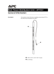
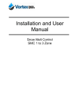
RPM
(Remote Power Manager)
User’s Manual
Table of Contents
1. IMPORTANT SAFETY INSTRUCTIONS ..................................................................................1
2. Introduction...............................................................................................................................3
3. RPM Package...........................................................................................................................4
4. Function....................................................................................................................................5
5. Installation ................................................................................................................................6
6. Web Interface ...........................................................................................................................7
7. Specifications..........................................................................................................................22
8. Obtaining Technical Assistance..............................................................................................23
9. Limited Product Warranty .......................................................................................................24
1. IMPORTANT SAFETY INSTRUCTIONS
This manual contains important instructions that should be followed during the installation and the
operation of the Remote Power Manager (RPM).
SAVE THESE INSTRUCTIONS
An Important Notice
•
•
•
•
•
•
•
•
•
•
•
•
•
•
•
•
•
•
To ensure safety in all applications ensure that a Qualified Service Personnel installs the system.
Make sure that the AC Utility outlet is properly grounded.
Do not open the unit there are no serviceable parts inside. This will void the warranty.
Do not try to repair the unit yourself, see Obtaining Service.
Please make sure that the input voltage of the RPM matches the supply voltage.
Use a certified input power cord with the correct plugs and sockets for the appropriate voltage
system.
Make sure the RPM is installed in the proper environment as specified. (0-50°C and 0-90% noncondensing humidity)
This RPM series is ONLY intended to be install in an indoor temperature controlled environment that
is free of conductive contaminants.
Do not operate the RPM in: extremely dusty and/or unclean areas, locations near heating devices,
water or excessive humidity, or where the RPM is exposed to direct sunlight.
Select a location, which will provide good air circulation for the RPM at all times.
This RPM supports electronic equipment in offices, telecommunications, process control, security,
and IT applications.
Servicing of RPM should be performed by Qualified Service Personnel Only.
CAUTION – To reduce the risk of fire, connect only to a branch circuit with over current protection in
accordance with the National Electric Code.
CAUTION - Connect the RPM to a two pole, three wire grounding AC wall outlet. The receptacle
must be connected to the appropriate branch protection (circuit breaker or fuse). Connection to any
other type of receptacle may result in a shock hazard and violate local electrical codes. Do not use
extension cords, adapter plugs, or surge strips.
Route power cords so they cannot be walked on or damaged.
CAUTION - To reduce the risk of electrical shock with the installation of this RPM equipment and the
connected equipment, the user must ensure that the combined sum of the AC leakage current does
not exceed 3.5mA.
CAUTION - To de-energize the outputs of the RPM: Disconnect the RPM from the AC wall outlet.
CAUTION - Do not install this device if there is not at least 30 feet (10 meters) or more of wire
between the electrical outlet and the electrical service panel.
1
Receiving Inspection
After removing your RPM from its carton, it should be inspected for damage that may have occurred in
shipping. Immediately notify the carrier and place of purchase if any damage is found. Warranty claims
for damage caused by the carrier will not be honored. The packing materials that your RPM was
shipped in are carefully designed to minimize any shipping damage. In the unlikely case that the RPM
needs to be returned to MINUTEMAN, please use the original packing material. Since MINUTEMAN is
not responsible for shipping damage incurred when the system is returned, the original packing material
is inexpensive insurance. PLEASE SAVE THE PACKING MATERIALS!
Para Systems Life Support Policy
As a general policy, Para Systems Inc. (Para Systems) does not recommend the use of any of its
products in life support applications where failure or malfunction of the Para Systems product can be
reasonably expected to cause failure of the life support device or to significantly affect its safety or
effectiveness. Para Systems does not recommend the use of any of its products in direct patient care.
Para Systems will not knowingly sell its products for use in such applications unless it receives in writing
assurances satisfactory to Para Systems that (a) the risks of injury or damage have been minimized, (b)
the customer assumes all such risks, and (c) the liability of Para Systems Inc. is adequately protected
under the circumstances.
Examples of devices considered to be life support devices are neonatal oxygen analyzers, nerve
stimulators (whether used for anesthesia, pain relief, or other purposes), auto transfusion devices, blood
pumps, defibrillators, arrhythmia detectors and alarms, pacemakers, hemodialysis systems, peritoneal
dialysis systems, neonatal ventilator incubators, ventilators for both adults and infants, anesthesia
ventilators, and infusion pumps as well as any other devices designated as “critical” by the United States
FDA.
2
2. Introduction
The RPM is an Internet ready device designed and equipped with an intelligent current-meter (True RMS) that
will indicate the total power consumption of the RPM.
Features:
Built-in web server.
Build-in true RMS current meter.
Easy setup.
7-segment LCD provides useful information.
Supports SNMP traps, which can be monitored by an NMS.
Supports SSL.
Sends emails and traps when an event occurs.
Provides an audible warning when the load exceeds the rating of the RPM.
Outlet protection via circuit breaker.
Individual control of the power outlets.
Group control of the power outlets.
LEDs visually indicate the status of the outlets.
Supports power on sequence.
3
3. RPM Package
The standard RPM package contains a Remote Power Manager unit with supporting hardware. The contents of
the package are:
Remote Power Manager unit.
Rackmount Brackets.
CD-ROM, which contains:
User Manual.
MIB files.
Adobe Acrobat Reader.
4
4. Function
Interface
7-segment LCD
Functions
Description
Ethernet
RJ45 port for the network communication.
Audible Alarm
Warning- 1 beep in 1 second.
Overload- 3 beeps in 1 second.
Note: The audible alarm will keep beeping until the current is lower than
the threshold by 0.5 amps.
Function Button
Press and release the function button to turn off the audible alarm.
Note: The overload alarm cannot be silenced.
Press and hold the function button for 2 beeps, then release will
display the IP address
Press and hold the function button for 4 beeps, then release will
change the way to set the IP address by either DHCP or fixed IP.
Press and hold the function button for 6 beeps, then release resets
the RPM back to the default setting.
Meter
3 digits will display the current and/or the IP Address.
ID
The identification of the RPM.
LED Indicator
SSL (yellow) LED: On means the web access is protected by SSL.
DHCP (green) LED: On means the RPM gets its IP address by DHCP.
Status (green) LED: Indicates each outlet’s power status.
Circuit Breaker
Overload protection.
5
5. Installation
This RPM series is ONLY intended to be install in an indoor temperature controlled environment that is free of
conductive contaminants. DO NOT operate the RPM in: extremely dusty and/or unclean areas, locations near
heating devices, water or excessive humidity, or where the RPM is exposed to direct sunlight. Select a location,
which will provide good air circulation for the RPM at all times. Route power cords so they cannot be walked on or
damaged.
Rack Mount Instructions
A) Elevated Operating Ambient Temperature - If installed in a closed or multi-unit rack assembly, the operating
ambient temperature of the rack environment may be greater than room ambient temperature. Therefore,
consideration should be given to installing the equipment in an environment compatible with the maximum
ambient temperature specified by the manufacturer.
B) Reduced Air Flow - Installation of the equipment in a rack should be such that the amount of airflow required
for safe operation of the equipment is not compromised.
C) Mechanical Loading - Mounting of the equipment in the rack should be such that a hazardous condition is not
achieved due to uneven mechanical loading.
D) Circuit Overloading - Consideration should be given to the connection of the equipment to the supply circuit
and the effect that overloading of the circuits might have on over current protection and supply wiring.
E) Reliable Earthing - Reliable earthing of rack-mounted equipment should be maintained. Particular attention
should be given to supply connections other than direct connections to the branch circuit (e.g. use of power
strips)."
Hardware
The RPM comes with brackets for mounting into a rack. To mount the RPM into a rack perform the following
procedure:
1.
Attach the mounting brackets to the RPM, using the four retaining screws provided for each of the brackets.
2.
Select the desired location for the RPM.
3.
Align the mounting holes of brackets with the notched hole on the vertical rail and attach with the retaining
screws.
4.
Connect the Ethernet cable to the RPM.
5.
Connect the output devices to the RPM outlets.
6.
Connect the input power cord of the RPM to the wall outlet.
Note 1:
The default setting for the IP address is DHCP enabled. If the RPM cannot get the IP from DHCP server, the IP
address will stay at the default IP address 192.168.0.216
Note 2:
To setup the network system for RPM, it is strongly recommended to build up the power monitoring network
system, which is isolated from the others, in order to maintain reliable system operation.
6
6. Web Interface
Login:
Enter the IP address of RPM in a web browser.
Note:
The default setting for the IP address is DHCP enabled. If the RPM cannot get the IP from the DHCP server, the IP
address will remain at the default IP address 192.168.0.216
The default User name is snmp.
The default Password is 1234.
7
Information: RPM
This screen displays the total current draw of the RPM.
8
Information: System
Indicates the RPM’s system information, including:
Model No.
Firmware Version
MAC Address
System Name
System Contact
Location
9
Control: Outlet
Indicates the RPM’s outlet on/off status and control.
Select the outlet by checking the box and then click the ON or the OFF button to control the outlet.
ON: Press the ON button to turn on the assigned outlets.
OFF: Press the OFF button to turn off the assigned outlets.
OFF/ON: Press the OFF/ON button to reboot the assigned outlets.
10
Control: Group
This allows you to group multiple outlets for group control.
Setting: Allows you to enter into the setting mode.
Outlet: Allows you to assign the outlet to a group.
Note:
The identified outlets need to be listed in the alphabetical order.
ON: Press the ON button to turn on the assigned group.
OFF: Press the OFF button to turn off the assigned group.
Active: Enables the controllable group.
11
Control: Schedule
This allows you to Schedule turning OFF/ON the RPM’s outlets.
Outlet: Assign the outlet to be controlled in this schedule.
Every: Set the schedule for an outlet using: a single day, an assigned weekly day, or every day.
Date: When selecting the single day option “sgl” under the “Every” column, a specific date must be
entered.
Begin:
End:
Action:
Turn on outlet at this time
None
ON
Turn off outlet at this time
None
OFF
Turn off outlet at this time
Turn on outlet at this time
OFF/ON
Turn on outlet at this time
Turn off outlet at this time
ON/OFF
Active: Enables the assigned schedule control.
12
Control: Ping Action
This allows you to Ping the device that is connected to a specific outlet and if there is no response the outlet can be
rebooted.
Automatically cycles power to a locked device connected to the RPM by rebooting the outlet.
Ping IP Address: Set the IP address of the device to be monitored by the RPM.
Response 10 minutes: The RPM will ping the assigned IP address once each minute. If the device does
not respond, then the RPM will repeat the ping once every minute, if the device does not respond after 10
attempts (10 minutes), the RPM will carry out the assigned action automatically.
Action: Select the outlet action “OFF” or “OFF/ON”
Active: Enables this function.
13
Configuration: RPM
Configure the outlet name and the delay time.
Name: Rename the outlet.
ON: Set the delay time for the power on sequence.
OFF: Set the delay time for the power off sequence.
Note:
The maximum delay time is 255 seconds.
Note:
After the RPM is plugged into the main power, the RPM will automatically start to sequentially turn on the outlets
according to the preset delay time. The default setting for delay time is one second for each outlet; therefore the 8
outlet RPM will take 8-seconds, the 24 outlet RPM will take 24-seconds to complete the start-up sequence.
If the RPM is unplugged from the main power before the start-up sequence is completed, the outlets, which are not
turned on will remain off. The next time the RPM is plugged into the main power, these outlets will not be
automatically turned on. These outlets can only be turned on via the web interface.
14
Configuration: Threshold
Set the warning and overload thresholds for entire RPM.
15
Configuration: User
Change the ID (User name) and the password.
The default ID (User name) is snmp and the password is 1234.
16
Configuration: Network
Enter the network information or enable the DHCP function.
The default setting for DHCP is enabled.
17
Configuration: Mail
When an event occurs, the RPM can send out email messages to predefined accounts.
Email Server: Input the email server’s domain name (does not support IP addresses).
Sender’s Email: Input the sender’s email address.
Email Address: Input the recipient’s email address.
The email message format is as follows:
Indicates the Outlets A~H-XXXXXXXX status in order
X=0: means the outlet is off.
X=1: means the outlet is on.
Note: Make sure the DNS server can resolve the email server’s domain name.
18
Configuration: SNMP
When an event occurs, the RPM can send out SNMP Traps to predefined targets.
Trap Notification: Set the IP address for the Trap receiver.
Community: Set the SNMP community.
The Read Community is public and fixed.
The Default Write Community is “public” and can be changed.
19
Configuration: SSL
This will enable the SSL function for the web communication.
User must input the correct ID and password to enable SSL function. The ID and password must be the same
as the setting on the “User” page.
20
Configuration: Time
This will allow you to setup the system time for the schedule control.
Internet Time Setting: Get the time from an assigned network timeserver.
System Time: Input the time manually.
21
7. Specifications
Model Number
RPM1581HVN
RPM20161VN
RPM2082HVI
RPM20162VI
12Amps
16Amps
16Amps
16Amps
Load Capacity (Max)
INPUT PARAMETERS
Single (1∅2W +G)
Number of Phases
Nominal Voltage
Frequency
Input Protection
OUTPUT PARAMETERS
Nominal Voltage
Frequency
Branch Circuit
Protection
Circuit Quantity
ENVIRONMENTAL
Operating
Temperature
Storage
Temperature
Operating/Storage
Humidity
100-120VAC
200-240VAC
50/60Hz
Re-settable circuit breaker
100-120VAC
200-240VAC
50/60Hz
UL 60950-1
One
+32° - +122°F (0° - 50°C)
+32° - +149°F (0° - 65°C)
0 - 90%, non-condensing
Operating
0 to 3,000m (0 to +10,000 ft)
Elevation
Storage Elevation
0 to 15,000m (0 to +50,000 ft)
PHYSICAL
Input Power Cord
10-feet
Input Plug
NEMA 5-15P
NEMA 5-20P
NEMA 6-20P
NEMA 6-20P
Quantity Output
8
16
8
16
Receptacles
Type Output
NEMA
NEMA
IEC 320
IEC 320
5-15/20R
5-15/20R
C13
2 – C19, 14 – C13
Receptacles
Rack Mounting
Horizontal (1U)
Horizontal (1U)
Vertical (Zero U)
Vertical (Zero U)
Format
Vertical (Zero U)
Vertical (Zero U)
Net Dimension
3.54 x 17 x 1.73"
2.2 x 49.02 x 1.73" 3.54" x 17" x 1.73" 2.2 x 49.02 x 1.73"
(90 x 432 x 44)
(56 x 1245 x 44)
(90 x 432 x 44)
(56 x 1245 x 44)
L x W x H (mm)
Net Weight
4.85
8.82
4.63
8.15
Lbs (Kgs)
(2.2)
(4.0)
(2.1)
(3.7)
Ship Dimensions
19.9 x 8.3 x 3.5"
53.5 x 8.7 x 4.3"
19.9 x 8.3 x 3.5"
53.5 x 8.7 x 4.3"
(505
x
210
x
90)
(1360
x
220
x
110)
(505
x
210
x
90)
(1360
x 220 x 110)
L x W x H (mm)
Ship Weight
5.51
11.02
5.29
10.36
Lbs (Kgs)
(2.5)
(5.0)
(2.4)
(4.7)
REGULATORY COMPLIANCE
Safety/Approvals
cUL, UL 60950-1, CE
22
8. Obtaining Technical Assistance
For Technical Support on the Web, please visit the Support section of our Web site or visit our online Discussion
Forum.
In order to diagnose the problem you are having, our technicians need the following information from you.
Installation Site:
Company Name:
Address:
City:
State:
ZIP code:
Contact Person’s Name:
Phone Number:
If you are a consultant,
Consultant Name:
Phone Number:
Computer System:
Fax Number:
Operating System and version:
System Manufacturer:
System Model Number:
NMS name and revision number:
RPM:
Model Name/Number:
Serial Number:
What are the symptoms?
Please have the information listed above ready when you contact us.
Contact Technical Support By:
Phone:
1-800-238-7272 / 1-972-446-7363
Fax:
1-972-446-9011
Web:
www.minutemanups.com/support/index.php (Technical Support)
www.minutemanups.com/phpBB2/index.php (Discussion Board)
www.minutemanups.com (Home Page)
23
9. Limited Product Warranty
Para Systems Inc. (Para Systems) warrants this equipment, when properly applied and operated within
specified conditions, against faulty materials or workmanship for a period of three years from the date of
original purchase by the end user. For equipment sites within the United States and Canada, this
warranty covers repair or replacement of defective equipment at the discretion of Para Systems. Repair
will be from the nearest authorized service center. Replacement parts and warranty labor will be borne
by Para Systems. For equipment located outside of the United States and Canada, Para Systems only
covers faulty parts. Para Systems products repaired or replaced pursuant to this warranty shall be
warranted for the remaining portion of the warranty that applies to the original product. This warranty
applies only to the original purchaser who must have properly registered the product within 10 days of
purchase.
The warranty shall be void if (a) the equipment is damaged by the customer, is improperly used, is
subjected to an adverse operating environment, or is operated outside the limits of its electrical
specifications; (b) the equipment is repaired or modified by anyone other than Para Systems or Para
Systems-approved personnel; or (c) has been used in a manner contrary to the product's operating
manual or other written instructions.
Any technical advice furnished before or after delivery in regard to use or application of Para Systems’
equipment is furnished without charge and on the basis that it represents Para Systems’ best judgment
under the circumstances, but it is used at the recipient's sole risk.
EXCEPT AS PROVIDED HEREIN, PARA SYSTEMS MAKES NO WARRANTIES, EXPRESSED OR
IMPLIED, INCLUDING WARRANTIES OF MERCHANTABILITY AND FITNESS FOR A PARTICULAR
PURPOSE. Some states do not permit limitation of implied warranties; therefore, the aforesaid
limitation(s) may not apply to the purchaser.
EXCEPT AS PROVIDED ABOVE, IN NO EVENT WILL PARA SYSTEMS BE LIABLE FOR DIRECT,
INDIRECT, SPECIAL, INCIDENTAL, OR CONSEQUENTIAL DAMAGES ARISING OUT OF THE USE
OF THIS PRODUCT, EVEN IF ADVISED OF THE POSSIBILITY OF SUCH DAMAGE. Specifically,
Para Systems is not liable for any costs, such as lost profits or revenue, loss of equipment, loss of use of
equipment, loss of software, loss of data, cost of substitutes, claims by third parties, or otherwise. The
sole and exclusive remedy for breach of any warranty, expressed or implied, concerning Para Systems’
products and the only obligation of Para Systems hereunder, shall be the repair or replacement of
defective equipment, components, or parts; or, at Para Systems’ option, refund of the purchase price or
substitution with an equivalent replacement product. This warranty gives you specific legal rights and
you may also have other rights, which vary from state to state.
PN: 34000462 R1
24