1
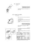
CX701 12” x 28” METAL LATHE with DIGITAL READOUT User Manual TABLE OF CONTENTS General Safety Instructions................................................................................................. 3 Specific Safety Instructions ................................................................................................. 4 Features .............................................................................................................................. 5 Physical Features................................................................................................................ 6 Set-Up ................................................................................................................................. 7 Un-Packing & Inventory ...................................................................................................... 7 Proper Grounding................................................................................................................ 8 Chuck .................................................................................................................................. 9 Steady Rest......................................................................................................................... 9 Follow Rest ......................................................................................................................... 10 Lathe Bed............................................................................................................................ 10 Headstock ........................................................................................................................... 10 Gearbox .............................................................................................................................. 11 Headstock Controls............................................................................................................. 11 Apron................................................................................................................................... 12 Saddle ................................................................................................................................. 12 Carriage Controls ................................................................................................................ 12 Lead Screw & Feed Screw.................................................................................................. 13 Tailstock .............................................................................................................................. 14 Tailstock Controls................................................................................................................ 14 Test Run.............................................................................................................................. 15 Speed Change .................................................................................................................... 16 Longitudinal Turning with Auto-Feed .................................................................................. 17 Manual Longitudinal Turning............................................................................................... 17 Facing and Recesses.......................................................................................................... 17 Turning Between Centers ................................................................................................... 18 Thread Cutting .................................................................................................................... 18 Change Gears Replacement............................................................................................... 19 Cross Slide Gib Screws Adjustment ................................................................................... 19 Top Slide Gib Screws Adjustment....................................................................................... 20 Chuck Run-out .................................................................................................................... 20 Headstock & Tailstock Alignment........................................................................................ 21 Main Spindle Bearings ........................................................................................................ 22 Lubrication........................................................................................................................... 22 Gearbox .............................................................................................................................. 22 Change Gears..................................................................................................................... 23 Saddle ................................................................................................................................. 23 Cross Slide.......................................................................................................................... 23 Cross Slide Hand Wheel ..................................................................................................... 23 Lead Screw ......................................................................................................................... 24 Tailstock .............................................................................................................................. 24 Maintenance........................................................................................................................ 24 Optional Chip Tray & Stand ................................................................................................ 25 Electrical Connections & Wiring Diagram ........................................................................... 26 Threading & Feed Table for CX701 .................................................................................... 27 Troubleshooting .................................................................................................................. 28 Parts Breakdown & Parts List ............................................................................................. 29 Warranty.............................................................................................................................. 48 2 GENERAL SAFETY INSTRUCTIONS FOR MACHINES Extreme caution should be used when operating all power tools. Know your power tool, be familiar with its operation, read through the user manual and practice safe usage procedures at all times. ALWAYS read and understand the user manual before operating the machine. CONNECT your machine ONLY t o the matched and specific power source. ALWAYS wear safety glasses respirators, hearing protection and safety shoes, when operating your machine. DO NOT wear loose clothing or jewelry when operating your machine. A SAFE ENVIRONMENT is important. Keep the area free of dust, dirt and ot her debris in the immediate vicinity of your machine. BE ALERT! DO NOT use prescription or other drugs that may affect your ability or judgment to safely operate your machine. DISCONNECT the power source when changing drill bits, hollo w chisels , router bits, shaper heads, blades, knives, or making other adjustments or repairs. NEVER leave a tool unattended while it is in operation. NEVER reach over the machine when the tool is in operation. ALWAYS keep blad es, knives and bits sharpened and properly aligned. ALL OPERATIONS MUST BE performed with the guards in place to ensure safety. ALWAYS use push sticks and feather boards to safely feed your work through the machine and clamp the work-piece (when nec essary) to prevent the workpiece from any unexpected movement. ALWAYS make sure that any tools used for adjustments are removed before operating the machine. ALWAYS keep the bystanders safely away while the machine is in operation. NEVER attempt to remove jammed cutoff pieces until the saw blade has come to a full stop. 3 CX701 - METAL LATHE SPECIFIC SAFETY INSTRUCTIONS broken parts, and any other conditions that may effect the tools operation. This machine is designed and intended for use by properly trained and experienced personnel only. If you are n ot familiar with the proper use of lathes, do not use this machine until proper training and knowledge has been obtained. Remove adjusting keys and wrenches. Remove all the tools used for adjustment before turning the machine on. Keep guards in place. Safety guards must be kept in plac e and in working order all the times to ensure safety. Be careful. Do not put your hand clos e to the cutter while the machine is running. Keep children and visitors away. All children and visitors should be kept at a safe distance from the work area. Never leave the lathe unattended while it is running. Wear proper apparel. Loose clothing, gloves, neckties, rings, bracelets, or other jewelry may get caught in moving parts. Non-slip footwear is recommended. Wear protective hair covering to contain long hair. Do not wear any type of gloves. Do not over-reach. Keep proper footing and balance at all times. Maintain tools with care. Keep tools sharp and clean for best and safest performance. Follow instructions given in the m anual for lubrication and replacing accessories. Always use safety glasses. For the safety of your eyes, safety glasses should be used while operating the lathe. Turn the power OFF. Before making any adjustments, make sure the switc h is in the “OFF” position and the cord is un-plugged from the power outlet. Do not use the lathe in dangerous environments. Do no ex pose the machine t o rain. Do not us e the machine in wet locations. Make sure you have read and understood all the s afety instructions in the manual and y ou are familiar with your metal lathe, bef ore operating it. If you fail to do so, s erious injury could occur. Check for damaged parts. Check for proper alignment of moving parts, WARNING The safety instructions given above can not be complete because the environment in every shop is different. Always consider safety first as it applies to your individual working conditions. 4 CX701 – METAL LATHE FEATURES MODEL CX701 – 12” x 28” METAL LATHE WITH VARIABLE SPEED As part of the growing line of Craftex metalworki ng equipment, we are proud to offer the CX701 a 12” x 28” Metal L athe with Digital Reado ut. The Craf tex name guarantees C raft Excellence. By follo wing the instructions and procedures laid out in this user manual, you will re ceive years of excellent service and satisfaction. The CX 701 is a professional to ol and like all power tools, prope r care and safety procedures should be adhered to. Motor....................................................1.5-HP, 1.1 KW, DC90 V, 12.3 Amp, 4600 r/min Swing Over Bed ...................................11.5”, (290mm) Swing Over Cross Slide .......................6.5”, (165mm) Distance Between Centers ..................27.5”, (700mm) Width of Bed ........................................7”, (180mm) Hole Through Spindle ..........................1.5”, (38mm) Taper in Spindle Nose .........................MT5 Number of Spindle Speeds ..................Variable Range of Spindle Speeds ....................50 – 850 RPM and 110 – 1800 RPM (Variable Speed) Number of Metric Threads ...................8 Range of Metric Threads .....................0.5mm – 3.0mm Number of Imperial Threads ................21 Range of Imperial Threads ..................8 – 56 T.P.I Range of Cross Feed...........................0.02 – 0.28mm / Revolution Range of Longitudinal Feed.................0.07 – 0.40mm / Revolution Tool Post Type .....................................4-Way Max Compound Slide Travel................3”, (80mm) Max Cross Slide Travel ........................5.5”, (140mm) Maximum Carriage Travel....................22”, (560mm) Tailstock Spindle Travel .......................3”, (80mm) Taper in Tailstock Spindle....................MT3 Overall Dimension of the lathe .............Length 55” x Width 27.5” x Height 26.5” Weight..................................................210 Kgs (462 lbs) Warranty ..............................................3-Years 5 CX701 - METAL LATHE PHYSICAL FEATURES A. Variable Speed Switch N. Half Nut Lever B. Headstock O. Auto Feed Lever C. ON/OFF Switch P. Cross Slide Hand Wheel D. Forward/Reverse Switch Q. Carriage Hand Wheel E. 3-Jaw Chuck R. Lead Screw F. Four Way Tool Post S. Feed/Thread Selector Knob G. Tail Stock Quill Lock Lever T. Oil Sight Glass H. Tail Stock U. Feed Rate Selector Knob I. Tail Stock Hand Wheel V. Feed Direction Selector Knob J. Tail Stock Lock Nut W. Chip Tray K. Compound Slide Traverse Lever X. Change Gear Protective Cover L. Lathe Bed Y. Threading/Feeding Table M. Thread Dial Indicator 6 SETUP Before setting up your machine you must read and understand the instructions given in this manual. The unpainted surfaces of this lathe ar e coated wit h a rust preventive waxy oil and you will want to remove this before starting assembly. Use a s olvent cleaner that will not damage painted surfaces. WARNING CX701 is a very heavy machine, do not over-exert yourself. Use fork truck or other mechanical devices for safe moving method LIST OF CONTENTS A. B. C. D. E. F. G. H. I. J. K. L. M. N. O. P. Q. QTY Face Plate........................................ Change Gears ................................. 4-Jaw Chuck .................................... 3-Jaw Chuck .................................... Steady Rest ..................................... Follow Rest ...................................... External Jaws for 3-Jaw Chuck........ Dead Center MT3 ............................ Reduce Sleeve (No. 5/3).................. Oil Gun............................................. Toolbox ............................................ 4-Way Tool Post .............................. Wrenches (8-10, 12-14, 17-19) ........ Hex Wrenches (3,4,5,6,8) ................ Chuck Keys...................................... Screw Drivers (Flat & Cross Head) .. Lathe with Chip Tray (Not Shown) ... 1 8 1 1 1 1 3 1 1 1 1 1 3 5 3 2 1 When setting up your machine, you will want to find an ideal spot where your metal lathe will most likely be positioned most of the time. Figure-1 CX701 Foot print UNPACKING To ensure safe transportation this machine is properly packaged and shipped completely in crates. When unpacking, carefully inspect the crates and ensure that nothing has been dam aged dur ing transit. Open the crates and check that the machine and the parts are in good condition. Figure-2 Inventory While doing inventory, if you can not find any part, check if the part is already installed on the machin e. Some of the parts come assembled with the machine because of shipping purposes. 7 PROPER GROUNDING Grounding provides a path of leas t resistance for electric current to reduce the risk of electric shock. CX701 is equipped wit h a 110-V single phase motor. To prevent electrical hazards, have a qualified electrician ensu re that the line is properly wired. This lathe is for use on a normal 110 volt circuit. Ma ke sure t hat the appliance is connected to an outlet having the same configuration as the plug. If an adaptor plug is us ed, it must be attached to the metal screw of the receptacle. WARNING Improper connection of the equipmentgrounding conductor can result in a risk of electric shock. Check with a qualified electrician if you are in doubt as to whether the outlet is properly grounded. It is strongly recommended not to use extension cords with your CX701. Always try to position your machine c lose to the power source so that you do n ot need to use extension cords. When it is necessary to use an extension cord, make sure the extension cord does not exceed 50-feet in l ength and the cord is 12-gauge to prevent motor damage. Your CX701 should be wired with a plu g having 3-prongs to fit a 3 prong grounded receptacle as shown in figure-3. Do not remove the grounding prong to fit it into a 2-pronged outlet. Always check with a qualified electrician if you are in doubt. Figure-3 110-Volts Outlet for CX701 8 CHUCK CX701 comes equiped with a 125mm, 3jaw chuck, a 125mm, 4-jaw chuck and a 220mm faceplate. Secure the steady rest to the lathe bed from below with a locking plate. A single c ap screw, along with a nut and washer hold the steady rest in place as shown in figure-5. The 3-jaw chuck is a scroll type chuck , meaning that all three jaws move in union when adjusted while the 4-jaw chuc k features four independent jaws. The 4-jaw chuck is used to clamp square or unevenlyshaped work-pieces. The chucks feature three hex nut and three set screws for mounting as shown in figure4. Figure-5 Steady rest TO SET-UP THE STEADY REST: Figure-4 Chuck mounting screws and nuts When removing the chuck, loosen the hex nuts, turn the was her count er-clockwise and pull out the chuck. See figure-4. STEADY REST The steady rest supports long, small diameter stock that otherwise c ould not be turned. The steady rest can also replace the tailstock to allow for cutting tool acces at the outboard end of your work-piece. To mount the steady rest: Make sure the switch is in the OFF position and the cord is disconnected from the power source. Loosen the hex nuts shown in figure-5. Loosen knurled screw and open the sliding fingers until the steady rest can be moved with its finger around the work-piece. Secure the steady rest in position. See figure-5. Tighten the knurled screw so that the fingers are snug but not tight against the work-piece. Tighten t hree hex nuts shown in figure-5 and lubric ate the sliding points with machine oil. 9 The sliding fingers of the steady r est shown in figure-5 should receive periodic lubrication when used, to prevent premature wear. two precision ground V-sideways are reenforced by heat hardening and grinding to guide the carriage and th e tailstoc k accurately. The main motor is mounted to the rear of the left side of the bed. FOLLOW REST The follow rest is mounted on the saddle with two cap screws shown in figure-6 and it follows the movement of the turning tool. Only two sliding fingers are required. The place of the third finger is taken by turning tool. The follow rest is used for turning operations on long s lender work-pieces. It prevents flexing of the work-piece under pressure from the turning tool. Set the fingers snug to the work -piece and make sure not to over tighten. Lubricate the fingers during operation to prevent premature wear. Figure-7 Lathe bed HEADSTOCK Made from high quality, cast iron for low vibration, the headstock is bolted to the bed with four screws. The headstock houses the main spindle with two precision taper roller bearings and the drive unit. The main spindle t ransmits the torque during the turning process and it also holds the work-piece and clamping devices. Figure-6 Follow rest installed LATHE BED The lathe bed is made of high quality iron and features high chee ks with strong cross ribs ensuring low vibration and rigidity. It integrates the headstock and drive unit, for attaching the carriage and leads crews. The Figure-8 Headstock 10 GEARBOX The gearbox is locat ed on the left side of the lathe and is moun ted on the bed. It is used to select the feeds for straight turning as well as for thread cutting. In order to achieve c ertain thread pitches, it is necessary to replace the change gears. The torque of the work spindle is transmitted to the feed gears and thus to the lead screw. FORWARD / REVERSE SWITCH: After the machine is switched ON, turn the switch to “F” position for counter-clockwise spind le rotation (forward). Turn the switch to “R” position for clockwis e spindle rotation (Reverse). Turning the switch to “0” position the spindle remains idle. Figure-9 Gearbox Figure-11 Forward / Reverse switch HEAD STOCK CONTROLS EMERGENCY ON/OFF BUTTON: The On/Off button allows t o start and stop the machine. FEED RATE SELECTOR KNOB: Use the feed rate selector knob to set the desired feed or thread rates. See figure-12. FEED THREAD SELECTOR KNOB: For thread selecting, shift the knob to the left and for feed selecting, shift the knob to the right. See figure-12. FEED DIRECTION SELECTOR KNOB: Select the carriage travel direction when the chuck is rotating in the forward direction or counter-clockwise as viewed from the front of the chuck. Figure-10 Emergency ON/OFF button 11 SADDLE The saddle is made from high q uality c ast iron and all s liding parts are smoothly ground to fit the V on the bed without play. Figure-12 Gearbox controls VARIABLE SPEED CONTROL KNOB: Turn the knob clock wise to increase the spindle speed and counter-clockwise to decrease t he spindle speed. T he poss ible speed range is dependent on the position of the drive belt. See figure-13. Figure-14 Saddle and apron CARRIAGE CONTROLS The carriage allows the cutting tool to move along the length of the lathe bed .The cross slide allo ws the c utting tool to travel perpendicular to the bed. The carriage features a top slide which allows linear movement of the cutti ng tool at any preset angle .This section will review the indiv idual controls on the carriage and provide descriptions of their uses. Figure-13 Variable speed control knob APRON The apron is mounted to the saddle and to the front side of the bed and it houses the half nut with an engaging lever for activating the automatic feed. The half nut gibs can be adjusted from the outside. LONGITUDINAL TRAVEL HAND WHEEL: Turning the longitudinal hand wheel, moves the carriage left or right along the bed .The control is helpful when s etting up the machine for turning, when manual movement is desired during turning operations. See figure-15. CROSS SLIDE HAND WHEEL: Turning the cross slide hand wheel, moves the cross slide towards or away from the workpiece. The graduated scale can be adjusted 12 using the s ame method as the longitudinal scale. See figure-15. TOP SLIDE HAND WHEEL: The top slide hand wheel controls the position of the cutting tool relative to the work- piece .The top slide is adjustable for angle as well as longitudinal travel. It can be adjusted a full 360°, if needed. See figure-15. TOOL POST: A four-way tool post is supplied with CX701. Cutting tools can be attached and removed by tightening or loosening the clamping bolt. See figure-15. HALF NUT LEVER: This lever engages and disengages the half nut on the lead screw. The lever is only engaged while turning threads in stock. A lockout devic e feature in the lever mechanis m engages when the feed selector is used. THREADING DIAL INDICATOR: This indicator tells you wh en to engage the half nut for threading process. See figure-16. Figure-16 Carriage controls Figure-15 Carriage controls AUTO FEED SELECTOR LEVER: Moving this lever upward engages the automatic longitudinal feed. Moving this lever down engages t he automatic traverse feed. See figure-16. LEAD SCREW AND FEED SCREW The lead screw and feed screw are mounted on the front of the machine bed. It is connect ed to the gear box at the left for automatic feed and is supported by bearing on both ends. WARNING Do not simultaneously engage the feed lever and the threading lever. Doing so will damage the lathe. Figure-17 Lead screw and feed screw 13 TAILSTOCK TAILSTOCK CONTROLS The tailstock slides on a V-way and can be clamped at any location. The tailstock has a heavy duty spindle and the spindle can be clamped at any loc ation with a clamping lever. The spindle is moved with a hand wheel at the end of the tailstock. TAILSTOCK HAND WHEEL: Turning th e hand wheel advances or retracts the quill in the tailstoc k. The graduated sc ale on the hand wheel is adjustable. See figure-20. QUILL LOCK LEVER: This lock lever locks the quill in position when tightened. See figure-20. TAILSTOCK LOCK LEVER: Turn this lock lever up to lock and down to unlock the tailstock in position on the lathe bed. See figure-20. ADJUSTMENT SCREW: This set screw is used to align the tailstock with the headstock. See pag e-20 for details on Center Alignment. Figure-18 Tailstock Make sure to install the securing screw at the end of the lathe as shown in figure-19 in order to prevent the tailstock from falling of f the lathe bed. Figure-20 Tailstock controls Figure-19 I nstalling the securing screw on the lathe bed 14 TEST RUN Once you have as sembled your lathe completely, it is then ti me for a test run to make sure that the lathe works properly and is ready for operation. Remove all the tools used for assembling the machine and make sure all the guards are in place. WARNING Before starting the lathe, make sure that you have read and understood the manual and you are familiar with the functions and safety features on this machine. Failure to do so may cause serious personal injury. To ensure the carriage contr ols do not move unexpectedly when the lathe is started, rotate the fe ed direction selector knob so that the arrow is pointing to the middle (neutral) position as shown in figure21. While test running the machine, check the following: The Emergency Stop & ON/OFF buttons are working properly. The chuck and jaws are properly secured and working properly. While the machine is runnin g, turn the variable s peed control knob clockwise to make sure it is working properly. Let the machine run for 10 minutes at the Low Speed. During the test run if there is any unusual noise c oming from the la the or it vibrates excessively, turn OFF the power switch immediately and disconnect from the power source Investigate if you can find out the problem with your machine. See page-28 for troubleshooting. If the machine is runn ing smoothly, proceed to the next step. Change the belt for High Speed and let the machine run for another 10 mi nutes. See page-16 for details on speed change. Turn the machine OFF and turn the Forward/Reverse switch to “R” position. Turn the m achine back ON and make sure the spindle is rotating clockwise (reverse). Figure-21 Feed direction selector knob Connect the cord to the power outlet and turn the machine ON. WARNING Do not make any adjustments while the machine is running. Failure to follow this warning can cause serious personal injuries to the operator and damage to the machine. 15 SPEED CHANGE The rotating speed of the headstock is controlled by the positi oning of the belts on the pulley s. These are accessed by removing the protective cover on the end of the headstock. Refer to the Threading & Feeding Table for Lathe on page-27 or the plate on the headstock to determine which belt combinations produc e what speeds. The speed settings availabl e on the CX701 are 50 – 850 RPM and 110 - 1800 RPM. TO CHANGE THE SPINDLE SPEED: Unscrew the two fastening knobs shown in figure-22 and remove the protective cover. Figure-22 Removing the cover Loosen the four nuts and screws shown in figure-23 and move the motor mounting pulley to release the tension on the belt. Once the belt tension is released, reposition the belt on the pulley s grooves for high or low spindle speed. Figure-23 Screws and nuts securing the motor mounting plate Position the belt on the pulleys for high and low speed according to figure-24. The low s pindle speed is 50 – 850 RPM while the hi gh spi ndle speed i s 110 - 1800 RPM. Figure-24 Belt position on the pulleys Once the belt is on the right grooves, move the motor pulley back to its position to tension the belt. Re-tighten the screws and nuts removed. IMPORTANT We suggest selecting the low speed. It provides stronger torque while operation. 16 LONGITUDINAL TURNING WITH AUTO-FEED MANUAL LONGITUDINAL TURNING Set the feed direction selector knob and feed rate selector knob shown in figure-25 to select the feed direction and feed speed. In this turning oper ation, the tool feeds parallel to the axis of rotation (longitudinal) of the work-piece. Manual feed is accomplished by turni ng the carr iage hand wheel on the lathe apr on or the top slide. The cross feed for the dept h of cut is achieved using the cr oss slide. See figure27. Figure-25 Feed rate se lector knob, feed direction selector knob and chart Use the chart on the lath for selecting the feed speed or the thread pitch. Select the proper gear set if the required feed or thread pitch can not be obtained with the installed gear set. Automatic feed is accomplished by mo ving the auto feed lever up. See figure-26. Figure-26 Auto feed selector lever Figure-27 Straight turning FACING AND RECESSES In the facing operation, the tool feeds perpendicular to the axis of rotation of the work-piece. The feed is made manually with the cross slide hand wheel. The depth of cut is made with the t op slide. See figure28. Figure-28 Facing & dressing 17 TURNING BETWEEN CENTERS For turning between centers, it is necessary to remove the chuck fr om the spindle. Fit the MT3 center into the 5/3 reducing sleeve (provided) and fit the reducing sleeve into the spindle taper. Mount the work-piece fitted with the driver dog between the centers. The driver is driven by a catch or face plate. See figure29. IMPERIAL THREAD: When c utting inc h threads, the half nut and threading dial are used to thread in a conventional manner. The threading and feeding table on page-27 or on the headstoc k, specifies at whic h point a thread can be entered using the threading dial. METRIC THREAD: The only dif ference in metric thread cutting is that the half nut must remain engaged during the entir e threading process. The thread dial c an not be utilized. Figure-30 Half nut and threading dial Figure-29 Turning between centers Set the machine up for the desired thread pitch. IMPORTANT Always use a small amount of grease on the tailstock center to prevent center tip from over heating. THREAD CUTTING Several dif ferent thre ads can be cut using the proper combination of gears and settings. Start the machine and engage the half nut. When the tool reaches the end of the cut, stop the machine by tu rning the motor off and at the same time back the t ool out off the work-piece so that it clears the thread. Do not disengage the half nut lever. Reverse the motor direction a llowing the cutting tool to traverse back to t he starting point. Repeat these steps until you ha ve obtained results. 18 LEFT AND RIGHT THREAD CUTTING: The left and right thread cutting is done using the feed direction selector knob. Turning the feed dir ection selector knob counter-clockwise, cuts left thread while turning it clockwise, cuts right thread. Select the proper gear set according to your requirements from the feed table given on the lathe (See page-27 Threading & Feeding Table for details ) and ins tall it onto the quadrant using nuts removed. Re-install the protective cover. . IMPORTANT We suggest selecting the low speed. It provides stronger torque while operation. CHANGE GEARS REPLACEMENT To replace the change gears: Make sure the switch is in the OF F position and the c ord is unpl ugged from the power outlet. Unscrew the two fastening knobs and remove th e protective cover to access th e change gears. Unscrew t he bolt from the lead screw and the square nuts shown in figure-31 from the quadrant bolts in order to remove the change gears. Figure-31 Change gears replacement GIBS ADJUSTMENT There are two main gib screws adjustment for the machine; the cross slide gib screws and the top slide gib screws. WARNING Make sure the switch is in the OFF position and the cord is disconnected from the power source before making any adjustments. Failure to do so can result serious personal injury. CROSS SLIDE GIB SCREWS ADJUSTMENT The adjustment gibs are located on the left side of the cross slide. To adjust gib, loosen the nuts holding the gibs. Tight en the gibs until e xcess movement is e liminated an d retighten the nuts. See figure-32. Figure-32 Cross slide adjustment gib screws 19 TOP SLIDE GIBS ADJUSTMENT Locate the adjustment gibs on the side of the top slide as show n in figure-36. Loosen the nuts holding the gi bs and then tighten the gibs until excess movement is eliminated. Once all the gibs ar e tightened properly, retighten the nuts. Figure-33 Top slide adjustment gibs screws CHUCK RUN-OUT If your lathe requires a higher level of accuracy, you may find it necessary to trueup the chuck to ensure minimal run-out. To check and correct the chuck run-out: Mount a piece of bar stock in the chuck. The stock should pr otrude approximately 50mm. Remove the bolts, securing the back plat e to the chuck. Tap along the edge of the mounting shoulder until the chuck and back plate are free of each other and thread back plate onto the spindle. Remove about 0.12mm of materi al from the surface that the ch uck mounts to . Be careful not to remove any material from the diameter of the shoulder. See figure-34. Figure-34 Turning the back plate Install the chuck onto the back plate and check the run-out. If the run-out is not within an acceptable range, it may be necessary to turn a new shoulder on the back plate. Before turning a new shoulder, measure the diameter of the recess in the back of the chuck accurately. Remove approximately one half of the thickness of the shoulder (ap proximately 1.5mm). Remove the same thickness off the face of the mounting surface. Use a dial indicator and measure the runout at the end of the bar . In most cases, the amount of run-out will not excee d 0.12mm over 50mm which should be accurate enough for most applications. If the run-out on the chuck is exces sive (e.g. greater than 0.15mm), the ex cess run-out should b e eliminated. Start by removing the chuck. Figure-35 Turning new shoulder on back 20 The finis hed diameter of the shoulder should be 0.025mm larger than the diameter of the recess in the c huck. This is a critical step in minimizing chuck run-out. Re-install the chuck and check for run-out. HEADSTOCK & TAILSTOCK ALIGNMENT The heads tock and tailstock alignment has been adjusted properly in the factory before the machine is s hipped to you. Howev er, after lengthy operation, the headstock and tailstock may be out of alignment. To check the centers alignment: Figure-37 Stock thicker at the tailstock end If the stock is thinner at the tailstock end, the tailstock needs to be moved away from you to the amount of taper. See figure-38. Center drill a 150mm piece of bar stock on one end and pos ition it between the headstock and tailstock as shown in figure36. Figure-38 Stock thinner at the tailstock end Figure-36 checking headstock and tailstock alignment TO MOVE THE TAILSTOCK: Turn approximately 0.025mm off diameter. Make sure the switch is in the OFF position and the cord is dis connected from the power outlet. Measure the stock with a microm eter. If the stock is thicker at the tailstock end, the tailstock needs to be moved towards you to the amount of taper. See figure-37. Adjust the tailstock offset to the amount by turning the adjustment screw shown in figure-39. 21 Re-tighten the two hex socket cap screws. CAUTION Make sure not to tighten the hex socket cap screws excessively or it will damage the bearing. Figure-39 Tailstock offset adjustment screw Turn another 0.5mm off the stock and check for taper. Repeat this procedure until the tailstock is aligned with the headstock. MAIN SPINDLE BEARINGS The main spindle bear ings are adjusted at the factory. If end play becom es evident after considerable use, the bearings may be adjusted. Loosen two hex s ocket cap sc rews in the slotted nut shown in figure-40. Tighten slotted nut until all end play is taken up. The spindle should still revolve freely. Figure-40 Main spindle bearing adjustment LUBRICATION Lubricate all slide-ways lightly before every use with 20W oil. WARNING Lathe must be serviced at all lubrication points and all reservoirs filled to operating level, before the lathe is placed into service. Failure to comply may cause serious damage. GEARBOX Oil must b e up to the indicator mark in th e oil sight glass as shown in figure-41. Top off with Mobilgear 627 or equivalent. Fill b y pulling the plug shown in figure-41. Figure-41 Gear box oil sight glass & fill plug 22 To drain the oil, remove the drain plug on the left side of headstock. See figure-45. Drain com pletely an d refill after first three months of operation. Then, change oil in the headstock annually. SADDLE Lubricate the four oil ports ( A) shown in figure-47 with 20W machine oil once daily. CROSS SLIDE Lubricate two oil ports (B) shown in figure44 with 20W machine oil. Figure-42 Gearbox oil drain plug CHANGE GEARS Apply a few drops of oil on the gears teeth and avoid getting oil on the pulleys and belt. Figure-44 Carriage and cr oss slide o il fill ports CROSS SLIDE HAND WHEEL Lubricate the oil port (C) on the cross slide hand wheel shown in figure-45 with 20W machine. Figure-43 Change gears Figure-45 Cross slide hand wheel oil port 23 LEAD SCREW Lubricate the oil ports (D & E) shown in figure-46 with 20W machine oil once daily. MAINTENANCE During the life of your machine, you will need to pr actice some regular maintenance to keep y our lathe in peak performance condition. 1. Treat the machine with care, keep it clean and grease and l ubricate it regularly. Only through good c are you can be sure that the working qualit y of the machine will remain constant. 2. Oil, grease and cleaning agents are Figure-46 Lead screw and feed screw oil ports TAILSTOCK Lubricate the two oil ports shown in figure47 once daily. pollutants and must not be disposed off through the drains or in normal garbage. Dispose of those agents in accordance with current local env ironmental regulations. Cleaning rags impreg nated with oil, greas e and cleaning wool in a suitable clos ed vessel and disposed of in an environmentally sound way. Do not put them with normal garbage. 3. Lubricate all slide ways lightly before every use. The change gears and the lead screw mus t also be lightly lubricated with lithium based grease. 4. During operation, t he chips which fall onto the sliding surfac e should be cleaned in a timely fashion. Frequent inspection s should be made to prevent chips from falling into the position be tween the carriage and bed way. Figure-47 Tailstock oil ports WARNING Make sure the machine is turned off and the cord is disconnected from the power source before servicing and replacing any components on the machine. 5. After the operation ev ery day, eliminat e all the chips and c lean different parts of the machine tool and apply machine tool oil to prevent from rusting. 6. Good housekeeping practice should be followed on a daily basi s keeping your lathe clean and well lubricated. 24 OPTIONAL STAND The CX701 features an optional stand Model CX701ST which can be bought separately. Figure-49 Mounting the lathe on the stand Figure-48 CX701 Stand inventory LIST OF CONTENTS A. B. C. D. QTY Left Cabinet..................................... 1 Right Cabinet .................................. 1 Connecting Brackets ....................... 2 Mounting Hardware.................... 1 Bag Once both the br ackets are properly secured to the cabinets, position the chip tray on the cabinets aligning the holes on the chip tray with the holes on the cabinet. Now, position the lathe on the stand using a fork truck. Align the holes on the machine with the holes on the chip tray and the cabinets. Open the cabinets and insert the bolts and washers (provided wit h the stand) from the top and tighten the nuts, from inside cabinets. STAND ASSEMBLY Before attaching the br ackets to the stands, thread the bolts into t he holes to break the paint ensuring smooth threading after. Connect the left and right cabinet by attaching t he bracket s to the cabinets and securing those using screws and washers provided. Figure-50 Lathe mounted on the stand 25 ELECTRICAL CONNECTIONS The CX701 Variable Speed Lat he is rated at 1.5-Horse Power, Single Phas e, 110-Volt and 12.3 Amps. Use the wir ing diagram for connecting the lathe to the main supply. Make sure the lathe is properly See page-8 for details. grounded. WARNING Connection of the lathe and all other electrical work may only be carried out by an authorized electrician. Failure to comply may cause serious injury and damage to the machinery and surroundings. WIRING DIAGRAM FOR CX701 26 27 28 29 30 CX701-QUADRANT & CHANGE GEAR ASSEMBLY 16 15 18 13 16 17 12 14 11 10 14 31 CX701-QUADRANT & CHANGE GEAR ASSEMBLY Parts No. 1 2 3 4 5 6 7 8 9 10 11 12 13 14 15 16 17 18 Description Shaft Snapring Washer Bushing Change Gear Change Gear Change Gear Change Gear Change Gear Spacing Ring Hex Socket Cap Screw Snapring Spacer Washer Washer Oil Cup Braket Key nut Washer Hex Socket Cap Screw Specification 80T 30T 75T 25T 80T M6x10 Φ6 Φ8 M8x45 Qty 2 2 2 1 1 1 1 1 1 1 1 1 1 2 1 2 1 1 32 33 34 35 36 37 38 39 40 41 42 43 44 45 46 47 WARRANTY CRAFTEX 3 YEARS LIMITED WARRANTY Craftex warrants every pr oduct to be free fro m defects in materials and agrees to co rrect such defects where applicable. This warranty covers three years for par ts and 90 days for labor (unless spe cified otherwise), to the original purchaser from the date of purchase but does not apply to malfunctions arising directly or indirectly from misuse, abuse, i mproper installation or ass embly, neglig ence, accidents, r epairs or alte rations or lack of maintenance. Proof of purchase is necessary. All warranty claims are su bject to inspection of such products or part thereof and Craftex reserves the right to inspect any returned item before a refund or replacement may be issued. This warranty shall not apply to con sumable pro ducts such as blades, bits, belts, cutters, chisels, punches etceteras. Craftex shall in no event be liable for injuries, accide ntal or otherwise, death to persons or damage to property or for incidental contingent, special or consequential damages arising from the use of our products. RETURNS, REPAIRS AND REPLACEMENTS To return, repair, or replace a Craftex product, you must visit the appropriate Busy Bee Tools showroom or call 1800-461-BUSY. Craftex is a brand of equipment that is exclusive to Busy Bee Tools. For replacement parts directly from Busy Bee Tools, for this m achine, please call 1-800-461-BUSY (2879), and have your credit card and part number handy. All returned merchandise will be subject to a minimum charge of 15% for re-stocking and handling with the following qualifications. Returns must be pre-authorized by us in writing. We do not accept collect shipments. Items returned for warranty purposes must be insured and shipped pre-paid to the nearest warehouse Returns must be acco mpanied with a copy of your original invoice as proof of purchase. Returns must be in an un-used c ondition an d shipped i n th eir original packaging a le tter explainin g your reason for the retu rn. Incurred shipping and handling charges are not refundable. Busy Bee will repair or replace the item at our discretion and subject to our inspection. Repaired or replaced items will be returned to you pre-paid by our choice of carriers. Busy Bee res erves the right to refuse rei mbursement or repairs or replacemen t if a third party without our prior authorization has carried out repairs to the item. Repairs made by Busy Bee are warranted for 30 days on parts and labour. Any unforeseen repair charges will be reported to you for acceptance prior to making the repairs. The Busy Bee Parts & Service Departments are fully equipped to do repairs on all products purchased from us with the exception of some products that require the re turn to their authorized repair dep ots. A Busy Bee representative will provide you with the necessary information to have this done. For faster service it is advisable to contact the nearest Busy Bee location for parts availabilit y prior to bringing your product in for repairs. 48