1
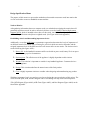
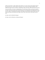
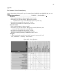
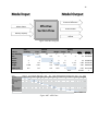
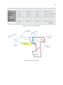
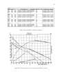
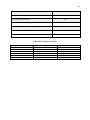
TEAM 10: THE VACUUNEERS Final Report Joseph Cortese Mohammed Alshammari Justin Manalo 4/30/2015 1 Table of Contents Letter of Intent………….………………………………………………………………………………………….…..2 Customer Needs Memo ……………………………………………………………………………………………….3 External Search and Benchmarking Memo …………………………………………………………….....5 Design Specifications Memo………………………………………………………………………………7 Concept Generation Memo………………………………………………………………………………...8 Concept Selection Memo ………………………………………………………………………………...10 Theoretical Analysis Memo………………………………………………………………………………12 First Prototype Evaluation Memo ……………………………………………………………………......14 Presentation (I)……………………………………………………………………………………………16 Component and Material Selection Memo……………………………………………………………….17 Fabrication Memo………………………………………………………………………………………...18 Safety Memo ……………………………………………………………………………………………. 19 Economic Justification Memo…………………………………………………………………………….20 Industrial Design Memo…………………………………………………………………………………..23 Alpha Prototype 2 Presentation………………………………………………………………………….. 25 Final Prototype Analysis Memo…………………………………………………………………………..26 Performance Memo……………………………………………………………………………………… 28 Final Presentation Poster………………………………………………………………………………… 29 Drill Report………………………………………………………………………………………………..30 Appendix…………………………………………………………………………………………………..33 Note: All figures/tables dubbed AXXX are part of the appendix. 2 Dear ME 340 Proctor, Team 10 - The Vacuuneers - hereby notify you of our plans to participate in the given project of converting a cordless drill into a handheld vacuum. We recognize the task established by the client in the document “Design Project - Cordless Handheld Vacuum” as well as the reasoning behind the requested proposals, as failure to meet these conditions would likely hurt our group’s professionalism. As mandated in the Project Description, we recognize that the same NiCd battery pack, battery pack connector and DC electric motor must be used. While researching vacuum cleaners, we have come to understand that all vacuum cleaners work by creating a difference in air pressure. Generally, a motor drives a fan which lowers air pressure INSIDE the appliance creating a partial vacuum. As a result, the atmospheric pressure outside the vacuum then forces the air inside the appliance, creating a suction process. For a vacuum cleaner to efficiently have a suction mechanism, a good motor is required, as well as an airflow. Each member of the team is concurrently enrolled in ME320: Fluid Flow, so all of us will only have a growing knowledge of how air intake will occur in our designs. However, the task of sucking up as much rice as possible shouldn’t need expert knowledge; we will likely rely on slight modifications and judgment during our prototyping and testing phase to see how much rice we can pick up. Our drill has a 21V motor capable of a range of rpms from 0-900 and should have the power to generate enough intake to perform the task. As our members have no sufficient expertise in the field of drill and vacuum mechanics, our design process will mostly be trial and error with on-the-job learning. Thus, we aim to focus on keeping our design simple and easily adjustable. This would also enable us to add any new part to our design if needed. Currently, we are in the planning stage, and we are aiming to finalize the overall project plan during the next week. During our planning stage, and throughout the entire design process, we aim to maintain a high level of organization in our operations, as we believe that organization is the key to efficiency and success. All group members would be participating in generating potential designs that would later be openly discussed by every group member, where members would be underlining the strengths and weaknesses of every design while still maintaining a positive atmosphere and refraining from negative criticism of any design. Once a design is approved by all members, fabrication of the necessary parts will commence and take much of the project duration. Subsequent to that, the group will physically test the handheld vacuum’s performance to see how it can be improved. The testing and modification stage will hopefully take no more than two weeks. After each weekly meeting, tasks are divided equally between all members. Members are to keep each other informed if any problem is to arise as well as about their work progress in general. If any major technical problems arise, we are able to get help from ME340 professors, Learning Factory TA’s, and other professors in their respective fields of study. Still, if such a problem was to occur, we will have two beta prototypes as dictated by the Project Description, so if any of the preliminary ideas fail, we will have a contingency plan in other concepts to minimize delay. Sincerely, Team 10 - The Vacuuneers Gantt Chart (see figure A025) 3 Customer Needs Memo The purpose of this memo is to display our group’s understanding of our customers’ needs and elaborate upon them. We established that our customers overall want a vacuum that performs well, is reliable, and is easy to operate. Our Perspective: Through our combined efforts, we established what we believe to be a list of what the customers need and want. We believe that for this product, they need and want the same qualities in the final product. Customers expect that vacuum cleaners should be easy to use, have exceptional performance, and be reliable. A handheld vacuum cleaner must be moderately lightweight to be usable. Also, the cost must be reasonable, fitting into the correct market. Our early research leads us to believe that $50 is reasonable, but this is too soon to determine our vacuum cleaners exact cost. We believe that the customer does not need a product that emphasizes on its appearance, but should look appealing enough to be competitive. Our Sources and our Market: We decided to survey the cleaning ladies in west commons, peers, and homeowners. The cleaning ladies are there because they use vacuums the most often. We believe they have the best opinion on what functionality they seek in a vacuum cleaner. However, most of those surveyed was the average consumer as they make up the largest portion of vacuum cleaner owners. The reasoning behind surveying cleaning ladies was that we were curious to see how different of an opinion they had compared to the average user. The average consumer’s input is the most important. These include homeowners and those living on their own. What distinguishes them from the heavy users is that there is some concerns that arise with heavy use of vacuum cleaners. It may not be productive to focus on those aspects, but to focus on making our product appeal to the most amount of people. Results/Findings: Through the surveys, interviews, and internet reviews, we have determined that many different users hold very similar opinions with regards to the qualities of vacuum cleaners. The primary needs of these users from our research are ones concerning the performance of the appliance. A few of those who were surveyed also linked this with the features. Although our overall survey results had the features near the bottom they are still important. The second most important quality of a vacuum, according to our findings, is reliability. The vacuum cleaner must be built to withstand many uses. This is further supported by the fact that most of the participants’ surveys claimed that they were moderate users. The third most important quality of a vacuum cleaner is the cost. In general, the participants did not value the luxury of having an expensive vacuum. The fourth most important feature was features, such as attachments and extensions. The final, and least important quality, is how it looks. This is not a surprise as this goes hand and hand with costs. As customers tend to buy low cost vacuum cleaners, they are less likely to focus on the aesthetics of vacuum cleaners in their search, as they are more expensive. In fact, all the participants we interviewed or surveyed keep their vacuum cleaners in a closet of some sort, so the aesthetics would never be appreciated. One interesting thing we found out from the survey is that almost all of them owned a “Hoover” product. They claimed that they were low cost, reliable, and performed well. Another interesting fact is that many of the participants did not own a handheld vacuum. This is because they consider a full sized vacuum more useful and can not justify spending more money on a slightly different product. 4 Additionally, we analyzed different online comments and reviews from Amazon and BestBuy websites that were about different handheld vacuum cleaners. Below is our ranking of the attributes sought by consumers: 1 - Ability to clean corners and tight spots 2 - Powerful suction 3 - Long battery life 4 - Lightweight 5 - Easy to grip 6 - Easily dumpable canister 7 - Sturdy 8 - Easy to maintain 9 - Works with a power cord in addition to the battery 10 -Removes pet hair 11 -Reasonable price Source: www.amazon.com, www.bestbuy.com. Based on amazon’s results and our results, the findings were nearly identical. This leads us to believe that the needs of the customer are clear and obvious, making this search a success. We will confidently be able to refer to this search for the remainder of this project. *detailed survey data etc. in Appendix (see figure A001). 5 External Search and Benchmarking Memo The purpose of this memo is to discuss the background research and benchmarking we conducted for our project. We also included our thoughts and reasoning for our decisions. Overall, we deduced that our vacuum cleaner would compete in the mid to low range of vacuum cleaners in terms of price. Our target customers consist of the everyday, average consumer. We plan to make cuts to the least important specifications and excel in the areas concerning the performance. The Current Market Our team has research current products regarding the market handheld, cordless vacuum cleaners, such as the one our team is designing. We do also recognize that handheld corded vacuum cleaners also exist in this market, but we only acknowledge the cordless ones, since many corded vacuum cleaners have a cordless variant. Products in the market are particularly marketed for one thing such as cost, aesthetics, specific purpose, and form factor. Dyson, for example, produces very expensive vacuum cleaners that have very great specifications on paper, such as high air wattage. Also, company’s battery powered vacuums seem to contain different types of batteries. Our Vacuum Cleaner’s Market We believe our vacuum cleaner to belong in the cordless-handheld vacuum cleaner market, particularly at the lower end. However, we aim to select proper specifications that allow this vacuum to function well without compromising the most important qualities. Many, if not all cordless, handheld vacuums, utilize cyclonic systems for air suction. The idea of a simple fan has not been used in commercial vacuum cleaners since the 1980’s. We have not yet ruled out certain technologies that do not compromise our budget range. Our range is most likely going to be around $50 dollars. This means that a product such as a Dyson handheld cordless vacuum would not be in our competitive range of price. We still plan to try and pull customers away from that type of product. 3 Products in our Market 3 Products that our team agreed to research were the Black and Decker Dustbuster, the Dyson DC34, and the Black and Decker Orb Vac. Black and Decker Dustbuster The Black and Decker Dust Buster was selected because we believed that the vacuum was the most practical type. It does not boast anything out of the unusual and appeared to aim at satisfying the largest amount of people. The Dustbuster is has a 14.4 V, lithium ion battery, rated at 1.5 amp hours. The suction is rated at 18.2 air watts. The total mass is 3 pounds. The dirt bowl volume is 20.6 ounces. The vacuum is water resistance and has an average run time of 9 minutes. The retail cost is $70. The best feature of this vacuum cleaner is its performance to cost ratio. It is the middle range vacuum cleaner out of the 3 we selected. The compromises made were in no way impactful to the customers, as shown in many reviews that our team researched. This will be the strongest competitor to our own vacuum. Dyson DC 34 The Dyson DC34 was selected because it had the best looking design and most features. However, this vacuum is also the most expensive, costing $150. The DC34 has a 22.2 V lithium ion battery and is rated 6 at 1.5 amp-hours. The suction is rated at 28 to 65 air watts due to a suction rate switch. The run time, therefor ranges from 6 to 15 minutes. The vacuum cleaner is also water resistant. We plan to make our vacuum compete and pull customers out of the “luxury vacuum cleaner” market. In order to do this, our product must be more well-rounded than the Dustbuster, and may have to look aesthetically pleasing as well. We will do our best to make the final prototype look refined within reason, in terms of total manufacturing cost. Black and Decker Orb Vac The last vacuum was the Orb Vac, by Black and Decker. This vacuum was a 4.8V, NICad battery. The output is only 8 air watts and the bowl volume is 6 ounces. The run time is 8 minutes and it is water proof. The cost is $50. This was a good choice to compare to our vacuum because it uses the same battery. We selected this vacuum cleaner because we believed that it was the very innovative. The shape and specifications are very odd compared to the other vacuums in the market. It has very low specifications which are a direct correlation of its overall cost and form factor. We believe that our product must be able to at least beat this in our specifications that we believe to be most important. Patents As in the U.S., most patents last 20 years after publication and approval. Each of the vacuum cleaners that we found has a specific patent for the product, all of which were made in the last 5 years. Each one of them contains technical drawings on a pdf with part numbers with their relative uses and orientation. There are also sub patents for technologies in the vacuums, but these are accounted for in the larger patent. Dustbuster: US 5047075 Orb Vac: App #: US 20120304417 A1 DC34: App # : US 21030207615 A1 7 Design Specification Memo The purpose of this memo is to present the methods used to transform customer needs into metrics that we can work with to create our handheld vacuum machine. Needs to Metrics: After gathering information about our customer needs, we embarked on assigning the metrics that will potentially meet those needs. In order to effectively do that, we used a Quality Function Deployment Diagram (QFD), which is intended to show how we take needs, turn them into weighted values, and then define what specifications satisfy those weighted needs. (See Figure A004 in the appendix). Establishing criteria and determining importance levels: Additionally, we used an AHP chart as a quantitative approach to determine the levels of importance of our different metrics.We started off by choosing five criteria in which our metrics fall under, and the assigned importance level of the different criteria will in turn reflect on our metrics. The chosen criteria are the following (See figure A005):- 1- Battery life: As the handheld vacuum would be used with no power cord, battery life is an aspect that customers pay a lot of attention to. 2- Suction power: The effectiveness of the appliance is highly dependent on this criterion. 3- Weight: This criterion is important to consider in any handheld appliance. Customers desire a lighter appliance. 4- Design: This criterion underlines the attractiveness of the final product. 5- Cost: A highly important criterion to consider when designing and manufacturing any product. With these importance levels, we now have a tool to use during the concept selection of this project. The values from the QFD, AHP, and Box Diagram can be used during each step of the selection process. *The QFD Diagram (Figure A004), AHP Chart (Figure A005), and Box Diagram (Figure A006) can be found in the Appendix. 8 Concept Generation Memo The Following Memo contains 3 possible concept designs for the Cordless Vacuum project by The Vacuuneers. Listed at the end, a black box diagram and another diagram were used in the making of these concepts. They were made to aid our group’s effort and keep ourselves on task. We plan to evaluate these concepts within the coming week. Concept #1 Description (Figure A026) This design would feature the most useful parts from the drill. These include the wiring, circuit, motor, gearbox, and battery. A watering pail of some sort could be used for the body. It would be cut in half and have a clamshell design for manufacturing and prototyping ease. The choice to remove one of the reduction stages from the drill would be to get a balance between torque and speed. The housing of the drill would be disposed of. This vacuum cleaner should be balanced, slightly in the front of the handle. This is why the battery is directly under the handle and the other heavier components are slightly in front of it. This will allow the user to easily run the vacuum cleaner at the correct orientation. A more accurate model that takes into account the weight of the parts may reveal that this vacuum may need weight added to balance it better. The fan is an axial fan, taking air in axially and expelling it axially. The canister is removable via a clip, for easy waste disposal and cleaning. The nozzle is also removable. There is a filter in front of the fan to protect it. The nozzle is angled downward and should rest flat on a surface when the vacuum is held at the handle. The brush was added to allow the nozzle to travel along carpet floors. (See figure A026 in the appendix.) Concept #2 Description (Figure A027) The handheld vacuum cleaner would use most of the parts from the available drill. Yet, instead of having two reduction stages, we would diminish that to one reduction stage to achieve faster rpm. A shaft is attached to the motor on one side and to the fan on the other side. The fan would be located inside a “bottle like” housing, while the motor would be outside, and the shaft would connect the two. In the intake opening of the “bottle-like” housing, a hose would be attached to aid in the air suction process. On the rear bottom of the same housing, an opening would connect the housing to the collection bin, where dust and other small particles would be collected. The collection bin would be attached to the vertical housing of the wiring, and the bin would have a door at the bottom to dispose of the dirt collected inside. An air exhaust opening would exist behind the motor to allow cooling off. Concept #3 Description (Figure A028) Since the half of the main components is part of the project constraints, focusing on how to put the remaining 4 components in place: the impeller, nozzle-head, collection bag & filter. Firstly, we needed to remove the clutch & chuck out of the design and replace it with the fan and the control-volume casing for it to function as a vacuum. The nozzle head has a wide mouth feeding into the smaller diameter of the control-volume, naturally increasing incoming speed of the rice. The curved/slanted filter still allows for the suction of the impeller to take place while also “guiding” the incoming rice down towards the collection bag with the help of gravity. The impeller will be driven by the same stock motor, but 9 gearbox will only have a single reduction stage. Because we are only using a single reduction stage we are gaining more rpm’s for the impeller, thus giving us more suction. The trigger and handle will be shifted at an angle to make room for the collection bag. Finally, the battery will be placed at the top of the vacuum; this allows for a better weight distribution. since the battery will take up most the weight once we remove the chuck & clutch, users will most likely have an uncomfortable time handling the vacuum if all of the weight is concentrated at the bottom of the handle; placing the battery approximately above the contact point (where the hand meets the handle) will give the vacuum a better, more natural center of mass. See Figure A029 for Black Box Diagram See Figure A030 for Black Box Combination Diagram 10 Concept Selection Summarizing this memo, our team has included our decision making ultimately leading to our main concept that we will be using in our analysis. Below our team has included an AHP, a concept scoring matrix, and a concept drawing. The rational and explanations for each of the charts are included above their respective figure or table. AHP (refer to figure A007 in the Appendix) For the AHP, we decided to base ours off of the one seen in the textbook. We added new categories, which included needed metrics such as weight distribution, containment system, filter, and airflow. We felt that this new AHP covered the fundamental metrics for our design. The rankings were not chosen at random, but were weighed individually against all others. This tactic generated a ranking of criteria according to its overall importance. This is not a perfect method, but is a simple yet effective way of prioritizing criteria to be used for selection. We decided that the suction power would trump every other metric not related to suction, yet hold similar importance to criteria such as airflow. It ended up being the most important criteria. Criteria such as the nozzle, airflow, and filter followed close behind as they were more important than “cost”, handle, etc. The metrics that had no impact on performance placed poorly because although they were important, they consistently were less needed then higher metrics such as suction power. Concept Selection Matrix (refer to figure A008 in the Appendix) We compiled all of the ratings for each of our team members’ individual concepts as a combined concept selection instead of selecting any single concept. The concept will stem from housing design detailed in Concept 3. Even though, Concept 3 scored the lowest overall, the housing was seen as the most convenient. Each component thereafter was selected in accordance with the housing so that it could easily be phased into the final product. This will allow for the flexibility of using any other component suggested as a backup in case the initial prototype does not function to our desired specifications. A big reason why the Mohammed’s design is the most beneficial is that it eliminates the need to fabricate many essential components: the handle, battery connection, wiring, motor placement and trigger placement. This will reduce manufacturing time and cost; the drill housing will already have a handle from the start and we would only have to connect the intake casing along with our designated containment system. While we are sacrificing weight distribution we can make up for this with a large collection area and minimal manufacturing. The filter concept was inspired by metal pasta strainers. Low cost metallic strainers offer numerous pores to allow for a smooth airflow and easy implementation into the product. The natural curve in pasta strainers allows us to easily direct the incoming rice into our containment system with the help of gravity and angle of impact. The wide-billed nozzle selected gives us a large area of suction while also having the necessary slanted edge to reach tight spaces. The wide-billed design also aides in speeding up the air intake, as it goes from a larger area to a smaller area, allowing for greater suction power. As for the remaining details such as overall weight, airflow and impeller, these were up for modification due to a lack of specifics. Overall weight was a relative matter seeing as no one actually placed measurements on anything such as housing, containment system, nozzle, filter, etc. Each concept replaced the chuck and gearbox with its own casing and containment system therefore any of the concepts could have weighed similarly. Concept 1’s airflow and impeller were selected for the final selection mostly due to its impeller having a radial exhaust and minimal clearance between fan and casing to allow for maximum suction. 11 Concept Drawing (See figure A009) Our final design incorporated the chosen metrics, decided on by our concept scoring, resulting in the combination seen below. We plan to use a bottle with a funnel for a nozzle, not manufacturing one. We also plan to use the drill’s original housing to save time. The containment is an extra cavity, added to the bottle of the nozzle. There are holes radially around the fan to dispense air. This seems like the most practical way to do so, as there is no worry for loss behind the fan that would exist in an axial design. The filter will be slanted to prevent build-up and be made out of wire and material, but also minimalize loss. 12 Cordless Vacuum: Theoretical Analysis Memo Overview of Analysis and Feasibility The ultimate goal of the tests was to identify the optimal conditions to produce the best Fan Static Pressure or the amount of suction. Initial, it is easy to address that the larger the power output, the better. Based on our theoretical Fan Static Pressure results, inversely, the smaller the inlet diameter, air velocity, and flow rate, the larger the Fan Static Pressure. For our best results to become a reality, we would have to have a nozzle that goes from a wide mouth to a small radius the size of half an inch. Based on our results, keeping everything the same while increasing the inlet diameter only another half inch causes the Fan Static Pressure to drop over 75%. Inversely, making a smaller inlet diameter smaller to 0.4 inches - only a 0.1 inch difference - and Fan Static Pressure increases by over 55%. However, realistically speaking, half an inch of diameter is already borderline too small to collect a large amount of rice quickly. Optimally, we should keep our diameter between 0.5 and 0.55 inches to maintain the best mass flow. Reasoning behind Calculations Ideally, at 100% efficiency (n), we would want our vacuum cleaner to have as much intake as possible. Therefore, by using the drill’s ability to change speeds and thus power output (W), we were able to calculate the estimated flow rates (Q) of each of the desired air velocities and inlet diameters. With the flow rates and air flow constant, we were able to find the Fan Static Pressure (H) for each condition. Finally, we took all of the theoretical Fan Static Pressures and changed the energy efficiency at which our vacuum operated to find all the possible Fan Static Pressures our vacuum could produce. This will allow us to have a guideline of what conditions are acceptable and what are useless. Variables List Q - is the volumetric flow rate D - is the impeller diameter ω - is the shaft rotational speed n - is the vacuum efficiency H - is the pressure or head developed by the fan/pump P - is the shaft power T - is the torque on the shaft Equations Equation 1, Area: A = πr2 Equation 2, Flow Rate: Q = (V ᐧ A) 𝑊 ᐧ 8.52 Equation 3, Fan Static Pressure: 𝐻 = 𝑄 Equation 4, Power: W = ω ᐧ T Equation 5, Fan Speed: Varied RPMs Equation 6, Air Flow Constant: 8.52 𝑄1 𝐷1 Equation 7, (𝑄2) = (𝐷2) Equation 8, ∆𝑃1 = ∆𝑃2 + ∆𝑃3 13 Equation 9, Predictions of System Performance Since we are taking out the gear-reduction stages completely, we will only have minimal torque on our fan. If we have close to our maximum rpm output, we would be able to produce approximately 23500 rpm, anticipating head loss. Based on Equation 4, we take advantage of the high rpm and low torque since the total power is maintained (approximately). The pressure losses are also factors to be considered for performance. However, we expect this analysis to overcompensate for the frictional/geometrical losses that occur due to the system design. According to Figure A012, the pressure drop at each component will affect the overall pressure drop of the unit. P1 and P2 are the inlet and exit of the system, respectively, and are at atmospheric pressure. Our design will be slightly different, since our design is centrifugal. The loss from E to F will not be on the fan, as in Figure A012, but will be the distance from the edges of the fan blades to the radial exhaust holes. The diagram describes the losses that occur from A to D due to friction and boundary layers created by the change of geometry. The filter will have a very large impact on the Pressure loss due to high friction. According to Figure A010 and Figure A013, the specific Fan Speed Equation and the Performance diagram indicate that an axial fan will suit our design best. This is because our Nsp is 38(US) and Axial performs better at higher specific speeds. However, our team will still be using a centrifugal design to mitigate losses after the fan and to simplify design. 14 First Prototype Evaluation Memo Fabricating our prototype involved methods such as 3D printing and using available materials in the learning factory, such as a 3”PVC pipe, steel mesh and duct tape. The overall cost of our alpha prototype was no cost. It is non-functional, but could be modified to run at a non-competitive level. This is due to a number of things that include lack of good geometric tolerances on many of the parts. After completing our prototype, we learned a lot of new ideas that we used to come up with a better second prototype. This can be seen near the end of this memo. Construction Process The impeller (see figure A016) was designed using Solidworks. This is because we thought the design was too complex to do in another way. We decided to use 5 blades to minimize frictional losses. We also chose to keep the design of the fins on the impeller simple, as we do not know how to improve them without testing. The diameter was chosen to what our theoretical analysis indicated (3in.) The hole for the impeller was chosen to be about the size of the sun gear on the shaft of the motor as this would be the most probable way to attach it. After receiving our printed fan, our team noticed the lack of control on the tolerance from a makerbot 3D printer. This led us to decide to not use this impeller in any real test. Also, we feel that even with good tolerance, the material would not be appropriate for rotating up to 30000 rpm. The nozzle was also designed using Solidworks. It goes from a 1 in. nozzle inlet to the full diameter of the fan (3 in.). We believed that for a prototype, this part could have been fabricated by other means, but the CAD program simplified our goal. We connected the nozzle to the air chamber by using hot glue. Our nozzle (see figure A017) connects to a cylinder (air chamber) that we made out of pvc pipe. There was a number of processes needed to change the pvc into something we could use. First, a pvc pipe was selected that had an inner diameter a little bit larger than 3 inches, because our 3 inch impeller needed to fit inside of it. Next, we used a rotating band saw to cut the pvc pipe to be approximately 6 inches in length. To allow for the fan to spin with more ease, we sanded a lip into the inside wall of the cylinder. Next, we used a drill press to drill 6 holes into the cylinder for an exhaust. They were radially spaced around where the fan would sit during operation. The collection bin (see figure A018) is to be permanently attached to the connection mentioned above via hot glue. The collection bin, being a Tum’s container, has a cap that could be taken off to remove the rice. The filter (see figure A019) is to be made out of a metal strainer, that was in sheets at the learning factory. Because we wanted the filter to be slanted inside the pipe, we need an elliptical shape to be cut out of the sheet rather than a circular. Wire cutters were used to cut the mesh. To get the mesh to fit in our air chamber, we placed it inside and hot glued each end to the pvc pipe while making sure that it was at the correct orientation. How to Improve There are many ways in which our prototype can be improved. First, we are going to redesign our centrifugal impeller to achieve better performance. Instead of having straight blades, we will have curved blades to more efficiently direct the air radially outward. For the impeller, the design will be enhanced with more curves and also be made out of more expensive material from a better 3D printer. We also need to make our components with more precise dimensions. Additionally, we are going to use a better method in holding the motor and attaching it to pvc pipe. We need to ensure that the motor does not move so that the impeller does not touch the inner walls of the 15 PVC pipe at any time. We can also improve the nozzle either by redesigning it with a smaller inlet or printing an extension to it that has a smaller inlet. The nozzle will also be sanded in order to make it smoother to reduce shear stress on our inflow. The ends of the nozzle will also be smoothed to reduce the size of the boundary layer. The collection bin will also be made out of plastic and will be super glued to the connector between the nozzle and fan. The exhaust will be changed in a way that provides greater air outtake. 16 Presentation Slides (Alpha Prototype I) See Figure A031 17 Component and Materials Selection Memo Components and Materials Plastic injection molding will be used to make most of the parts in our mass produced device. Using this method will enable us extensively customize our parts and maintain durability. Additionally, abs plastic is a relatively light and cheap material. The components that will be injection molded will be the following: housing, collection bin, nozzle extension, on/off trigger part, and mesh filter. The impeller will be made from abs plastic that is plastic injection molded. The battery casing will also be plastic injection molded. The switch will be plastic injection molded as well. Common Off-the-Shelf (COTS) Components Since the product is going to be mass produced, our team decided to manufacture the majority of our parts, as this allows us to get good tolerances and minimal machining. For example, on our prototype, we used a pvc pipe for a chamber. Instead of machining the chamber, we will have those features all molded during the molding of the chamber. Since we will be using a clamshell design, we will need COTS components such as screws washers. A spring will be used in the trigger. Wires for the electronics will also be purchased. The motor will be purchased from a distributer as well as the battery. Potential Environmental Consideration (DFE The purpose for our group using DFE on our design is to exhibit ethics for the environment so that potential customers would find our product desirable. Also, creating a DFE is almost standard when mass producing anything. From the very beginning of material selection, we knew we wanted to reduce the number of different materials and make most of the vacuum cleaner recyclable. The plastic used in the injection molding would be re-melted if need be, which is a nice feature. Even the nickel cadmium battery is recyclable. With the above knowledge, a medium between cost efficiency and environmental awareness did not seem incredibly challenging. Excluding the sustainability, as all vacuum cleaners predominantly use plastic for their vacuum cleaners for obvious reasons (cost, recycling), our group prepared the chart below. Table for DFE or Materials See Table A001 in Appendix Final Drawing of Manufactured Parts See the appendix. 18 Fabrication The purpose of this memo is to elaborate on how a mass-produced version of our vacuum cleaner would be fabricated Processes The air chamber would be created by injection molding and would pass through an inspection where obvious defects could be pointed out. Excess plastic would be cut away with a tool. The nozzle and impeller would be made in a similar matter. An assembly line would have people place the parts and use optimal equipment to place in the screws the quickest. The parts will travel on a belt and each part of the assembly will be done by a different operator. The half of the clamshell from the housing would be placed on the drill-type electronic housing. The trigger would be installed separately. The electronics would be checked with a voltmeter to ensure that they work. The battery would also be installed. The impeller would be placed on the shaft of the motor and that portion would be attached to the housing with screws and washers. The filter would be placed in the air chamber, snapping into the grooves. The nozzle would also be placed in as well as the collection bin. The other air chamber clamshell would be snapped into place, locking the once movable components. Screws and washers would secure the air chamber. The impeller would be attached to the motor and the air chamber would be connected to the electronic housing. A test would be used at the end to see if the vacuum cleaner could function, as well as testing if the vacuum cleaner could generate a pressure difference as stated. This test would only be done on every 50 – 100 made in order to not waste time. The product will be boxed with a user manual and warranty. A set of nozzle attachments would be a welcome addition as well. There would also be a power adapted in order to charge the battery. Exploded Assembly View The exploded assembly view shows how our parts fit together in order to understand the product. Each part has its own detailed drawing included in this report. (See figure A024) 19 Safety Memo Since our handheld vacuum machine is a user-based product, user safety is of utmost importance. The purpose of this memo is to demonstrate our team’s understanding of the consideration that goes into the design and implication of a product. We researched other products on the web in order to familiarize ourselves with this field as safety regulations are not taught in engineering courses. Examination Examining the different safety standards and government consumer product safety regulations provided enabled us to understand the major safety issues that we have to consider. The current regulations focus mostly on the safety of the batteries and the appliance’s outer cover. Batteries are often the most hazardous parts in household appliances, and thus it is of paramount importance to ensure that the mass production version will not include any battery defects and will be compliant to the safety regulations and standards. Additionally, our mass production version will also have a properly fitted and rigid housing that provides proper insulation. Proper insulation will minimize the risk of potential electrocution and will enable our product to meet standard regulations. Our product complies with the following safety standards: UL 1017, IEC 62885-4 Ed.1. Action Additional to the mandatory safety regulations, we will voluntarily raise the safety standards on our product because consumer safety is a main priority. As hair dryers have similar internal parts and safety hazards, we have also examined the historical safety incidents of hair dryers to properly avoid similar incidents from occurring in our hand held vacuum machines. We also plan to adopt the safety standards of hair dryers that we believe can be applicable to our hand held vacuum machine. One report regarding hair dryer electrocution is provided in the references. References: 1. UL 1017: http://ulstandards.ul.com/standard/?id=1017&edition=8&doctype=ulcsa 2. IEC 62885-4 Ed.1:http://www.iec.ch/dyn/www/f?p=103:30:0::::FSP_ORG_ID,FSP_LANG_ID:1395,25 3. Hair Dryer Electrocution report: http://www.cpsc.gov/PageFiles/132317/hairdryers.pdf 20 Economic Justification Memo Production Cost Reasoning: Housing & Trigger (ABS Injection Molding) | “Housing is customized to contain nozzle” Mass of housing = 0.200 kg. 100,000 housings require 20,000kg. Add 30% extra material for production scrap purposes; resultant = 26,000kg. See Table A002 in Appendix for BOM #1 26,000k kg * 0.43 $/kg = $11,180 Per Unit = $0.1118 DC Motors and Wiring $100,000 DC Motors = ($1.50)*(100,000) = $1,500,000 Custom ABS Impeller Mass of Impeller = 0.050 kg 100,000 Units *0.050 kg = 5,000 kg Collection Bin Mass= 0.120kg 100,000 Units * 0.120 kg =12,000 kg 12,000kg * 1.44 $/kg = $17,280 Add 30% extra material for production scrap purposes; resultant = $22,464 Injection Molds Prices Housing Mold Capital Cost: $56,000 Collection Bin Mold Capital Cost: $10,000 Injection Molding Machines: ABS Injection Molding Machine Capital Cost: 45,000 PMMA POM ABS Injection Molding Machine Price (BJ160S5) (Polycarbonate) Injection Molding Machine Capital Cost: 10,000 21 XT-H450 High-efficiency Servo Motor Polycarbonate Injection Molding Machine Retail Price: In order to accurately measure the minimum retail price (break-even price) of our handheld vacuum cleaner, both the capital costs and the operating costs need to be considered. The production will continue for four (4) years. Capital Costs include the costs of injection molds and injection molding machines. Our total Capital Costs are equal to $121,000 and should be paid up front (56k + 10k + 45k + 10k = 121k). This type of cost is a one-time cost at year 0 in our cash flow diagram. Operating Costs are the costs that are paid on an annual or more frequent basis. They include material, production, overhead, labor, and other costs. These are included in the adjusted BOM provided below (For the purpose of our calculations, a new BOM is generated that excludes “fixed costs”; fixed costs will be calculated as part of the Capital Costs.) Capital Costs: See Table A003 for BOM#2 $121,000 * Capital Recovery Factor (A/P,0.1,4) for r=10%, years=4 $121,000 * 0.31547 = $38,171.87 Operating Costs: 3,588,538.00 Annual Equivalent Cost: $3,588,538.00 + $38,171.87 = $3,626,709.87 (Total Production Cost per Year for Four Years) Minimum Retail Price = $3,626,709.87 / 100,000 units = $36.26/unit (not adjusted to inflation) For 25% profit, we would set our retail price at $45/unit. We believe that this is indeed a good investment because our annual profits would be $873,290, equating to $3,493,160 during the whole four year period. Note: Annual Equivalent Cost Method was used rather than Net Present Value Method (NPV) because it would more accurately project the unit production cost. (Source: Engineering Economy Class IE 302). References: 1. http://www.alibaba.com/product-detail/rs555-china-12v-dc-electric-motor_60156247551.html 2. http://www.portercable.com/Products/ProductDetail.aspx?ProductID=20734 22 3. http://www.grainger.com/product/GRAINGER-APPROVED-Screw-Refill1YU14?s_pp=false&= 4. http://www.alibaba.com/trade/search?fsb=y&IndexArea=product_en&CatId=147106&SearchTex t=abs+injection+molding+machine 5. http://www.custompartnet.com/estimate/injection-molding/ 6. Appendix B Exhibit 13-19 Injection Molding Cost Examples 23 Industrial Design Memo The purpose of this memo is to explain how our team feels about our product’s compliance to the aesthetic and ergonomic needs of the customer. Ergonomic and Aesthetic Features The overall colors scheme of our vacuum cleaner is a mixture of black and white. Minimizing color usage simplifies the appearance of the product. This compliments the simple, yet compact design. We believe that this approach will make the product look like it can be stored in most places while not being used. The collection container is a cylinder for ergonomic and aesthetic reasons. It is ergonomic due to the cylindrical shape and its location on the unit. The shape of it accommodates the size of the average female hand span, which is roughly 6.7’’. Research showed that most tools are designed according to the average male features, but we opted to go against this trend. We believe it is better to downsize ergonomic parts when given the option. The location of the collection bin allows it to be gripped in addition to the handle with the on switch. The collection container is also plasti dipped to give it a comfortable texture that does not slip out of the hand. The entire unit does not favor a left or right handed individual, providing equal functionality to any two-handed user. The buttons are red, making them easy to spot. The balance of the vacuum cleaner is slightly towards the nozzle from the center. We chose this because the vacuum cleaner will be slightly tilted forward during use. The weight factor compliments the motion of use. The unit is also easy to disassemble due to nonpermanent methods of attachment, such as screws, being used. The overall appearance of the product is aesthetically pleasing. This is due to the strategic use of curves and color to make the product look highly professional and functional. Ease of Use and Safety As mentioned above, the color of the buttons (red) makes them very easy to see from a new customer’s perspective. The added power control from the trigger is a nice extra feature that does not complicate the use. The battery-removal button is intuitive and located right above the battery. A light turns on, signifying when the trigger is being pulled. This makes the vacuum easier to use for those with hearing disabilities. The unit is lightweight, weighing only two more pounds than the average hand drill. Our team has also taken measures to ensure the safety of our customers. The exhaust holes are small and have a warning label on them. We did this because we considered the possibility of someone placing their hair in a hole and their hair getting caught in the impeller. The holes design also protects against the impeller failing at high speed and shattering. The breakable pieces of the impeller are too large to fit through an exhaust hole. Every removable part of the unit is too large to be swallowed, which makes it safe around young children. The unit also shuts off when overheated to prevent injury. 24 Anthropometric Data Considered The average female hand span is 6.77”. This was considered in the design of the collection container and handle. The average length of a female forearm is roughly 10’’. With ones elbows near their side and forearms outwards, the weight distribution of the product should be manageable. Having a center of mass away from oneself does go against this idea, but since the unit is compact it should still be easy to handle. References http://www.theaveragebody.com/average_hand_size.php http://www.censusatschool.ca/dataresults/2006-07/length-of-forearm/ 25 Alpha Prototype 2 Presentation Slides See figure A032 in appendix. 26 Final Prototype Performance and Evaluation Memo The purpose of this memo is to report and reflect on our team’s final prototype. The information below will consist of the construction, description, and pictures of our prototype as well as performance data. New Parts of the Prototype The next impeller (see figure A033) housing is a 3 to 1 ½’’ adapter. This worked perfectly with the acrylic disk design that we had backing our impeller. A series of drills were used to make holes, and an air tool was used to turn those holes into the shape shown above. This new exhaust compliments the new impeller design by facilitating more airflow then the single large hole before. This design was better than the original because we needed to shrink our nozzle. We were not getting enough suction before. Changing the nozzle to have a maximum size of 1’’ allows for rice to travel a farther distance through the until to the collection container. Our final design will be using this, but we will be attaching the acrylic disk by a sturdier means rather than just tape (see black ring of electric tape above). A new nozzle (see figure A034) was needed to ensure better airflow and airspeed at the inlet. The previous prototype was very ineffective at this. We designed this new one in Solidworks and used a 3D printer to make it. We also attempted to fabricate the attachment seen below the nozzle, but the 3D printer failed in doing so two hours into the job. We quickly went to a department store and found a better solution than we thought. The 3-way pipe allows sturdy connection between the collection container and airflow system. Only small 1 ‘’ long rings of 1 ½ ‘’ pvc pipe needed to be cut and fitted to make a connection between each end of the 3-way pipe. Our filter was also fitted into the bottom of this subsystem by cutting out a circular pattern of a strainer. This was molted and fitted into a cone shape which was then glued to the edge of the pvc pipe. When this attachment is connected to the 3 to 1 ½ ‘’ adapter, the filter is sturdy enough for service. This is a much simpler design then before. The collection container is another piece of pvc pipe (not shown due to being plasti dipped) with a cap on the bottom. The original did not have sufficient air speed to suck up rice, and there was no container connection. We did one coat of plasti tip, but will dip the other parts multiple times. The new impeller (see figure A035) was a combination of our last 2 designs, taking the best parts of each and molding them into a far superior design. From the first impeller, we took the blade design, realizing that it provided much better airflow. From the second design, we took the stem-type attachment hole and dome shape. This made the impeller very sturdy with a lower rotational moment of inertia. The stem-type hole allows a safe connection between sun gear and impeller. We chose to use the Dimension printer for this task, as the quality is much higher. Many makerbot-made impellers can explode without trauma even being dealt to it while in use. The accuracy is way too unreliable for this type of functionality. 27 Air Speed Comparison of the Old vs New Impeller Our first test (see figure A036) our group chose to perform was a test between the old and new impeller’s airspeed from the adapter we used. This was used instead of the nozzle because the adapters’ shape compliments the shape of the manometers fan (a circle). We also thought this was a just call because this was only to compare the performance rather than get readily useful data. See table A008. View of Overall Final Design As seen in figure A037, our design is very small and compact. We tried to reduce the size in order to get minimal losses and boost the overall durability. What was once considered a huge problem was the attachment between the 3” pvc pipe and the 3” to 1 ½’’ adapter. Joe suggested that the solution would be to use some sort of connection to join the two pieces. He found 5 wood screws and decided to drill holes. With great caution and thought beforehand, a method of clamping and drilling holes was conducted. The final outcome was a solid, sturdy connection. What was interesting was the mixed opinions on this method of connection. Some TA’s thought it would be risky, but two of the more experienced TA’s encouraged it. Because of the method used to drill the holes, no measurements were needed to assure that everything was in line. This connection bridged the joining of two, already sturdy, subsystems. It was also a surprise that the unit stands upright even after the added weight offsets the original center of mass. Joe also gave a shaking test to get a feel for the overall sturdiness of the unit and was very pleased. Future Modifications From our data above, our group saw an improvement of 44.55% in the new design. We were shocked of how much better this new design performed. However, before we could test this design on rice, the impeller broke. We will have to request for the ability to print another. We did test to see if the old design could pick up a lot of rice and it did, but we have no analytical data to prove this (but we have video proof). We also didn’t want to test an old design and would like to wait a day for a new print to test our new design. We predict our current design (disregarding the broken impeller), will perform optimally and that changes will only be for aesthetics. The only thing we did not like about this prototype was the connection between the acrylic and adapter, but it held. Everything else performed very well. We are going to plasti dip everything, so that the colors are orange and black. 28 Performance Analysis Memo The purpose of this memo is to document our finding on how our team’s vacuum cleaner performed. Included are our test results and reflection on how well our vacuum cleaner performed. The first section we included, however was an air speed comparison that we completed out of concern for a new impeller’s design. This design compared the other two impeller used in the “Final Prototype Analysis Memo”. Comparison We conducted an air speed comparison (see table A004) of our two original impellers. Soon after, they each broke. We then had a slightly modified third impeller printed. In order to see if our modifications caused a loss in performance, we did an airspeed test on the new impeller. We feel that this data is valuable to this memo even though the data is not entirely reflecting the performance of our vacuum cleaner, but only the impeller. Results of the Comparison Upon examining our results, we conclude that our slight modification had little to no impact on the performance. We predict that the slight decrease in performance can be accredited to the loss in battery power due to the fact that we did not fully charge the battery beforehand. With confidence in our design, we preceded to develop a test in which a simulation of the competition could be replicated. The Test We decided to have our vacuum cleaner complete a task that was similar to the competition we will be competing in. We selected 17 cubic inches of rice to be sucked up. This is about 1.1 cups with a unit conversion, which is the amount we will be doing in the competition. Our vacuum would be timed on how fast it could suck up this amount of rice with the orientation of the rice being that of a 6 inch pancake. The keep consistency, we allowed the operator to get the impeller spinning at full speed before the time began. We repeated this test 10 times and averaged the results seen in table A005. Results According to our data above, we can determine that our vacuum cleaner performed adequately. Our hopes were that an average of less than 10 seconds would be achieved. This was because upon looking at past results of other vacuums, a time of less than 10 seconds is very fast. 29 Final Presentation Poster See figure A038 in appendix for poster. 30 Drill Report I a. Overview The purpose of this report is to cover an inspection and test that our group conducted on our Drill Master 18 V Cordless Drill. The information in this report includes (I) answers to preliminary questions, (II) pictures of the parts of the cordless drill with descriptions,(III a) Dynamometer Test Sketch, (III) completed table 1, (IV) Data plots for the drill, (V) completed table 2, and (VI) Conclusions and reflection. The purpose of this project is creating a handheld, cordless vacuum cleaner, using parts from this cordless drill. Our vacuums will compete against other teams aimed at similar markets. The test will only judge the overall performance of our vacuum on its suction. I b. Answers to Preliminary questions (#’s4, 6, 8, 9, 10, 11, 12, 13) 4. The purpose of the chuck needing a reversed “snap” to remove it is to prevent the chuck from flying off during use. The reverse screw is held in tight, so removing it requires that the drill is in its highest torque setting, so the action pops the screw, rather than just rotating it. 6. Sketch of Drill (see figure A039) 8. Gear Ratio: 2 stages of planetary gear system Each Stage: (R+S) x T_y = R x T_r +T_s x S; Stage 1: T_y/T_s = S/(R+S) = 15/60 = 1/4 R = # teeth in ring gear = 45 S = # teeth in sun gear = 15 P = # teeth in planet gears = 15 T_y = # turns in planet carrier T_r = # turns in ring gear T_s = # turns in sun gear Stage 2: T_y/T_s = S/(R+S) = 9/54 = 1/6 R = 45 P =18 S=9 Overall = ¼ *⅙ = 1/24 So, for ever 24 times the sun gear rotates 1 turn, the last carrier rotates 1 time. Gear Ratio = 24 : 1 (in : out) The types of gears used are sun, planet, ring, and carrier gears. Some alternatives involve screw type gears and belts, but the one seen in the drill do a great job at having a compact form factor as well as effectiveness in reducing the gear ratio. The more gears you have, the higher the cost. This may include more housing to hold the gears as well as safe fails such as the clutch system. 9. Bearings Bearings, at a first glance, there may appear to be ball bearings. However, their purpose is to be part of the clutch. In the event that a torque limit is breached, the drill will not break due to this clutch system. 10. Motor 31 The type of motor used is a dc motor. DC motors are more appropriate for a drill than an AC motor due to factors such as speed variation control and availability. The installation is also much easier than an AC motor. They are also cheaper and in safer than ac motors. The DC motor on this drill also has the option to be reverse due to a polarity toggle. 11. Cooling The drill is cooled via ports near the first “sun gear”, and through small holes around it. Air flow along with heat flow (heat sink) within the motor is the method of cooling. Copper components have high heat thermal gradients to transfer the heat. There is also a circuit that removes power to the drill if it reaches a certain temperature. 12. Part Count The total number of parts in the drill is 50 as per the manufacturer’s handbook. (31/50) 62% of the parts can be purchase from a vendor (screws, wires, washers…). The gear box can be shrunk, but that will compromise the functionality. This drill is minimalistic on parts except the temperature sensor, polarity toggle, and LED light. 13. DFA A clamshell design allows the body to be easily cast into a mold. However, screws must be fastened on both sides of the drill, which means that a machine would either have to turn the drill to do this or be double sided. The trigger is a little difficult to install by hand due to it connecting to the circuit and also fastening, simultaneously, to the seat. II. Pictures of Parts of cordless drill (See figure A040) Description of Parts: A). The DC motor is the consumer of power. It provides the rpm for the first sun gear. B). The polarity toggle can reverse the turning direction of the drill. It also doubles as a safety when in the middle position. C). The circuits consist of switches and wires that bring current throughout the drill to its parts. There is a thermal circuit that shorts the whole system if a certain temperature is reached within the DC motor. E). The Switch has a minimal and maximum activation distance that can change the amount of power used by the motor. This will change the rpm of the drill from low to high. F).The gearbox housing holds the planetary gear system. G). The secondary gear system is a continuation from the first system to convert high rpm into high torque. H). The ring gear is a stationary means of transferring the advantage from each planetary gear stage. I.) The Screws hold plastic components together. The chuck holds the rotating bit of the drill. J). The spring and washer are used for the clutch system to prevent the drill from potential damage. K). The Second Sun Gear works in the same way as the first sun gear, transferring higher rpm. L.) The spacer spaces the metal parts. M.) The planet gear rotates around the sun gear. N). The planet gear rotates around the sun gear. III a. Drill Dynamometer Test and Sketch The dynamometer (see figure A041)was used to rate our drills efficiency. The voltage and current where taken while changing the torque on the dynamometer. The purpose of this was to obtain accurate results in order to be able to compare the results to other teams. These results are seen below. 32 III. Table 1: Drill Performance (see table A006) IV. Data Plots for our Drill (See figures A043 and A044) V. Table 2: Technical Features of Our Drill (See table A007) VI. Conclusion and Reflection Conclusion After conducting baseline observations on our drill before dissecting it, we realized that it actually sounded and ‘felt’ a lot better than it did at the start. This was probably happening because a lot of the grease/lubricant was removed from the gearbox. This leads us to believe that too much grease on the inside of a gearbox is not good for any machine. If we were to test the drill again, then we might actually get slightly better results across the board. Another hypothesis is that if our team were to remove the stock lubricant used in the drill’s gearbox with a non-corrosive solution and replaces it with a more efficient, non-stock, premium lubricant; we can achieve even more of an increase in efficiency, even if just by a little bit more. This could give us an added boost in the motor’s output rpm. Reflection Even if we can get a 200% increase in our motor’s output rpm, we would still not be able to do any mechanical work without the gearbox and its 2 reduction stages. All the power our drill can muster is a direct correlation to the amount of rpms we can generate to the number of reduction stages we implement. The more reduction stages we use in our gearbox, the more power we will have in mechanical output. 33 Appendix The Vacuuneer’s Short Vacuum Survey Answer the questions for the specific type of vacuum cleaner (handheld or non-handheld) that you own: Name:_______________ Vacuum Name and Brand:_____________________ Handheld ( ) Non-handheld ( ) · Handheld: Is the vacuum adequate for what you need it for? Yes No How often do you use the vacuum? Rarely(once a month) Moderate (once every week) Often (more than every other day) Do you feel you overpaid for the vacuum? Yes No Would you recommend this vacuum to peers? Yes No · Normal Vacuum: Is the vacuum adequate for what you need? How often do you use the vacuum? Rarely(once a month) Moderate (once every week) Often (more than every other day) Do you feel you overpaid for the vacuum? Yes No Would you recommend this vacuum to peers? Yes No Would you consider purchasing a handheld vacuum? Yes No · Thoughts: o Rank in order what you feel is the “ideal” vacuum for your needs (1 to 5) cost performance reliability looks features Figure A001: Survey Questions Figure A002: Benchmarking 34 Figure A003: QFD for Handheld Vacuum Cleaners Figure A004: QFD (Needs to Metrics) 35 Model Output Model Input Pressure Difference Effective Suction Flow Motor Power Suction Power Battery Capacity Airflow Figure: A005 Box Diagram Criteria User Handling Cost Suction Power Weight Design Battery Life User Handling 1.5 2 1 0.333 0.5 Suction Cost Power 1 0.667, 0.5 1 2 0.5 0.25 0.5 Battery Weight Design Life 1 3 2 0.5 2 4 1 0.5 0.2 0.5 2 1 0.667 0.75 5 1.5 1 2 Total Weight 8.167 0.173041 2 11 0.233066 2 1.33 0.5 1 Sum: 14 5.83 2.95 5.25 47.197 0.296629 0.123525 0.062504 0.111236 1 Figure A006: AHP Chart Criteria Ease of Use Cost Suction Power (Impeller) Overall Weight Design Nozzle Filter Handle Distribution of Weight Containment System Airflow Ease of Use 1.00 1.50 2.00 1.00 0.33 0.50 2.00 1.00 1.00 1.67 4.00 Cost Suction Power Weight Design 0.67 0.50 1.00 3.00 1.00 0.50 2.00 4.00 2.00 1.00 2.00 5.00 0.50 0.50 1.00 1.33 0.25 0.20 0.67 1.00 0.50 0.50 0.75 2.00 1.00 0.50 2.00 0.50 0.50 0.33 0.50 2.00 1.00 0.50 1.33 0.50 1.00 0.50 1.00 0.75 2.00 1.00 2.00 1.33 Nozzle 2.00 2.00 2.00 1.33 0.50 1.00 1.00 0.33 0.33 0.33 1.00 Filter 0.50 1.00 2.00 0.50 2.00 1.00 1.00 0.50 0.33 0.75 1.00 Handle Distribtution of Weight Containment System Airflow 1.00 1.00 0.60 0.25 2.00 1.00 1.00 0.50 3.00 2.00 2.00 1.00 2.00 0.75 1.00 0.50 0.50 2.00 1.33 0.75 3.00 3.00 3.00 1.00 2.00 3.00 1.33 1.00 1.00 0.50 1.00 0.33 2.00 1.00 1.00 0.50 1.00 1.00 1.00 0.50 3.00 2.00 2.00 1.00 Sum Figure A007: AHP Chart Total 11.52 16.50 24.00 10.42 9.53 16.25 15.33 8.00 9.50 9.50 20.33 150.88 Weight 0.076332 0.109358 0.159067 0.069039 0.063185 0.107701 0.101626 0.053 0.062964 0.062964 0.134765 1 36 CONCEPT SCORING MATRIX Concept 1(Joe) Selection Criteria Ease of Use Cost Suction Power (Impeller) Overall Weight Design (Housing) Nozzle Filter Handle Distribution of Weight Containment System Airflow Concept 2(Mohammed) Concept 3(Justin) Final Concept Weight 0.076332185 Rating (1-5) 4 Score 0.305328738 Rating (1-5) 3 Score 0.228996554 Rating (1-5) 3 Score Best Option 0.228996554 Concept 1 (Joe) 0.109358431 1 0.109358431 5 0.546792153 1 0.109358431 *Moot Point* 0.159066808 4 0.636267232 3 0.477200424 3 0.477200424 Concept 1 (Joe) 0.069039413 2 0.138078826 3 0.20711824 3 0.20711824 0.063184871 5 0.315924355 3 0.189554613 3 0.189554613 Concept 1 (Joe) 0.107701485 2 0.215402969 3 0.323104454 5 0.538507423 Concept 3 (Justin) 0.101626016 1.5 0.152439024 1 0.101626016 5 0.508130081 Concept 3 (Justin) 0.053000177 5 0.265000884 3 0.15900053 3 0.15900053 0.062963945 5 0.314819724 4 0.251855779 4 0.251855779 Concept 1 (Joe) 0.062963945 3 0.188891835 4 0.251855779 3.5 0.134764935 4 0.539059738 2 0.269529869 2 0.269529869 Concept 1 (Joe) 3.180571757 3.006634411 3.159625751 Rank 1 3 2 Figure A009: Selected Concept Concept 1 (Joe) 0.220373807 Concept 2 (Mohammed) Total Score Figure A008: Concept Scoring Matrix Concept 2 (Mohammed) Final Judgement: COMBINATION 37 Figure A010: Spreadsheet of Theoretical Analysis Figure A011: Consumer Pressure Curve (from patent 3894505’s creator) 38 Figure A012: Dynamic Pump Type Effectiveness (from instructor) Figure A013: Example of Pressure Drop with Losses (Provided By Instructor) 39 Air Velocity (ft/min) Flow Rate (Q) ft3/min Inlet Diameter (ft) Drill Power (watts) Fan Static Pressure (in/water) Pump specific Speed (m/s) nf=1.0 4000 4000 4000 4000 4000 4000 4000 4000 4000 4000 4000 4000 50 00 50 00 50 00 50 00 50 00 50 00 50 00 50 00 50 00 50 00 50 00 50 00 60 00 60 00 60 00 60 00 60 00 60 00 60 00 60 00 60 00 60 00 60 00 60 00 5.45415 3912 21.8166 1565 49.0873 8521 5.45415 3912 21.8166 1565 49.0873 8521 5.45415 3912 21.8166 1565 49.0873 8521 5.45415 3912 21.8166 1565 49.0873 8521 6.81769 2391 27.2707 6956 61.3592 3152 6.81769 2391 27.2707 6956 61.3592 3152 6.81769 2391 27.2707 6956 61.3592 3152 6.81769 2391 27.2707 6956 61.3592 3152 8.18123 0869 32.7249 2347 73.6310 7782 8.18123 0869 32.7249 2347 73.6310 7782 8.18123 0869 32.7249 2347 73.6310 7782 8.18123 0869 32.7249 2347 73.6310 7782 0.041666666 67 60 0.083333333 33 60 50 00 50 00 50 00 50 00 50 00 50 00 50 00 50 00 50 00 50 00 50 00 50 00 60 00 60 00 60 00 60 00 60 00 60 00 60 00 60 00 60 00 60 00 60 00 60 00 5.45415 3912 21.8166 1565 49.0873 8521 5.45415 3912 21.8166 1565 49.0873 8521 5.45415 3912 21.8166 1565 49.0873 8521 5.45415 3912 21.8166 1565 49.0873 8521 6.81769 2391 27.2707 6956 61.3592 3152 6.81769 2391 27.2707 6956 61.3592 3152 6.81769 2391 27.2707 6956 61.3592 3152 6.81769 2391 27.2707 6956 61.3592 3152 8.18123 0869 32.7249 2347 73.6310 7782 8.18123 0869 32.7249 2347 73.6310 7782 8.18123 0869 32.7249 2347 73.6310 7782 8.18123 0869 32.7249 2347 73.6310 7782 0.041666666 67 60 0.083333333 33 60 50 00 50 00 50 00 50 00 60 00 60 00 60 00 60 00 5.45415 3912 21.8166 1565 49.0873 8521 5.45415 3912 6.81769 2391 27.2707 6956 61.3592 3152 6.81769 2391 8.18123 0869 32.7249 2347 73.6310 7782 8.18123 0869 0.041666666 67 60 0.083333333 33 60 0.125 60 0.041666666 67 45 0.083333333 33 45 0.125 45 0.041666666 67 30 0.083333333 33 30 0.125 30 0.041666666 67 15 0.083333333 33 15 0.125 15 93.7267 2796 23.4316 8199 10.4140 8088 70.2950 4597 17.5737 6149 7.81056 0663 46.8633 6398 11.7158 4099 5.20704 0442 23.4316 8199 5.85792 0497 2.60352 0221 74.9813 8237 18.7453 4559 8.33126 4707 56.2360 3678 14.0590 0919 6.24844 8531 37.4906 9118 9.37267 2796 4.16563 2354 18.7453 4559 4.68633 6398 2.08281 6177 62.4844 8531 15.6211 2133 6.94272 059 46.8633 6398 11.7158 4099 5.20704 0442 31.2422 4265 7.81056 0663 3.47136 0295 15.6211 2133 3.90528 0332 1.73568 0147 84.3540 5516 21.0885 1379 9.37267 2796 63.2655 4137 15.8163 8534 7.02950 4597 42.1770 2758 10.5442 569 4.68633 6398 21.0885 1379 5.27212 8448 2.34316 8199 67.4832 4413 16.8708 1103 7.49813 8237 50.6124 331 12.6531 0827 5.62360 3678 33.7416 2207 8.43540 5516 3.74906 9118 16.8708 1103 4.21770 2758 1.87453 4559 56.2360 3678 14.0590 0919 6.24844 8531 42.1770 2758 10.5442 569 4.68633 6398 28.1180 1839 7.02950 4597 3.12422 4265 14.0590 0919 3.51475 2298 1.56211 2133 74.9813 8237 18.7453 4559 8.33126 4707 56.2360 3678 59.9851 0589 14.9962 7647 6.66501 1766 44.9888 2942 49.9875 8824 12.4968 9706 5.55417 6472 37.4906 9118 nf=0.9 4000 4000 4000 4000 4000 4000 4000 4000 4000 4000 4000 4000 0.125 60 0.041666666 67 45 0.083333333 33 45 0.125 45 0.041666666 67 30 0.083333333 33 30 0.125 30 0.041666666 67 15 0.083333333 33 15 0.125 15 nf=0.8 4000 4000 4000 4000 0.125 60 0.041666666 67 45 omeg a= 1884.96 rad/s Vdot ft3/ = 49.1 min ft/s^ g= 32.2 2 H= 0.376 38.0272 Nsp= 2779 psi 40 4000 4000 4000 4000 4000 4000 4000 4000 50 00 50 00 50 00 50 00 50 00 50 00 50 00 50 00 60 00 60 00 60 00 60 00 60 00 60 00 60 00 60 00 21.8166 1565 49.0873 8521 5.45415 3912 21.8166 1565 49.0873 8521 5.45415 3912 21.8166 1565 49.0873 8521 27.2707 6956 61.3592 3152 6.81769 2391 27.2707 6956 61.3592 3152 6.81769 2391 27.2707 6956 61.3592 3152 32.7249 2347 73.6310 7782 8.18123 0869 32.7249 2347 73.6310 7782 8.18123 0869 32.7249 2347 73.6310 7782 0.083333333 33 45 50 00 50 00 50 00 50 00 50 00 50 00 50 00 50 00 50 00 50 00 50 00 50 00 60 00 60 00 60 00 60 00 60 00 60 00 60 00 60 00 60 00 60 00 60 00 60 00 5.45415 3912 21.8166 1565 49.0873 8521 5.45415 3912 21.8166 1565 49.0873 8521 5.45415 3912 21.8166 1565 49.0873 8521 5.45415 3912 21.8166 1565 49.0873 8521 6.81769 2391 27.2707 6956 61.3592 3152 6.81769 2391 27.2707 6956 61.3592 3152 6.81769 2391 27.2707 6956 61.3592 3152 6.81769 2391 27.2707 6956 61.3592 3152 8.18123 0869 32.7249 2347 73.6310 7782 8.18123 0869 32.7249 2347 73.6310 7782 8.18123 0869 32.7249 2347 73.6310 7782 8.18123 0869 32.7249 2347 73.6310 7782 0.041666666 67 60 0.083333333 33 60 0.125 45 0.041666666 67 30 0.083333333 33 30 0.125 30 0.041666666 67 15 0.083333333 33 15 0.125 15 14.0590 0919 6.24844 8531 37.4906 9118 9.37267 2796 4.16563 2354 18.7453 4559 4.68633 6398 2.08281 6177 11.2472 0736 4.99875 8824 29.9925 5295 7.49813 8237 3.33250 5883 14.9962 7647 3.74906 9118 1.66625 2941 9.37267 2796 4.16563 2354 24.9937 9412 6.24844 8531 2.77708 8236 12.4968 9706 3.12422 4265 1.38854 4118 65.6087 0957 16.4021 7739 7.28985 6619 49.2065 3218 12.3016 3304 5.46739 2464 32.8043 5479 8.20108 8696 3.64492 831 16.4021 7739 4.10054 4348 1.82246 4155 52.4869 6766 13.1217 4191 5.83188 5295 39.3652 2574 9.84130 6436 4.37391 3971 26.2434 8383 6.56087 0957 2.91594 2648 13.1217 4191 3.28043 5479 1.45797 1324 43.7391 3971 10.9347 8493 4.85990 4413 32.8043 5479 8.20108 8696 3.64492 831 21.8695 6986 5.46739 2464 2.42995 2206 10.9347 8493 2.73369 6232 1.21497 6103 nf=0.7 4000 4000 4000 4000 4000 4000 4000 4000 4000 4000 4000 4000 0.125 60 0.041666666 67 45 0.083333333 33 45 0.125 45 0.041666666 67 30 0.083333333 33 30 0.125 30 0.041666666 67 15 0.083333333 33 15 0.125 15 Figure A015: Fluid Analysis Figure A016: Impeller 41 Figure A017: Nozzle Figure A018: Collection Bin Figure A019: Filter 42 FigureA020: Airflow Chamber Drawing Figure A021: Containment Chamber Drawing 43 Figure A022: Impeller Drawing Figure A023: Inflow Nozzle Drawing 44 Figure A024: Full Assembly Drawing Figure A025: Gantt Chart 45 Figure A026: Vacuum Cleaner Concept #1 46 Figure A027: Vacuum Cleaner Concept #2 47 Figure A028: Vacuum Cleaner Concept #3 Output Input Electrical Power Handheld Vacuum Machine Pressure Differential at the nozzle Manual trigger Figure A029: Black Box for Concept Design Vibrations 48 Figure A030: Combination Black Box Diagram 49 Figure A031: Slides from Presentation I Table A001: DFE of Materials used on the Vacuuneer’s Customer-Ready Product Material Parts Recyclable Waste Durability Recovery ABS plastic -Air Chamber -Impeller -Nozzel -Cannister -Electronics Housing Remeltable Minimal, due to current processes Lightweight and tough. -Parts are screwed/ clamped together Steel -filter, COTS’s -remeltable minimal Very tough -detachable Battery (NiCd) -Battery -yes -maintainable n/a -removable (rechargable) 50 Table A002: BOM #1 Table A003: BOM #2 51 Figure A032: Alpha Prototype 2 Slides Figure A033: Impeller Housing 52 Figure A034: New Nozzle and Airflow Subsystem Figure A035: New Impeller Figure A036: Anemometer 53 Figure A037: Our Final Design Table A004: First Comparison Trial # 1 2 3 4 5 Average: Old Impeller Airspeed (ft/min) 5760 5650 5680 5790 5520 5680 New Impeller Airspeed (ft/min) 8100 8205 8294 8255 8201 8211 Final Modified Impeller Airspeed (ft/min) 7994 8025 8120 8004 8306 8089.8 Table A005: Results from Performance Trial # 1 2 3 4 5 6 7 8 9 10 Average: Time (seconds) 8.85 7.58 6.58 7.52 6.81 7.02 7.14 6.45 6.89 6.99 7.18 54 Figure A038: Final Poster 55 Figure A039: Sketch of Drill a. DC Motor b. Polarity Toggle c. Circuit e. Switch and Circuit f. Gearbox Housing g. Secondary Gear System 56 h. Ring Gear k. Second Sun Gear i. Screws and Chuck l. Spacer n. Planet Gear Figure A040: Parts of Drill Figure A041: Dynamometer Test Sketch j. Spring and Washer m. Planet Gear 57 Table A006: Drill Test Results Dynamometer Test Data 900 120 800 100 600 80 500 60 400 300 40 Current (amps) RPM or Watts 700 rpm amps watts (input) watts (output) 200 20 100 0 0 0 20 40 60 80 100 120 140 External Load Torque (oz·in) Figure A042: Drill Performance Results from Dynamometer Test Data 58 Dynamometer Test Data 800 50 700 40 Rpm 600 500 30 400 20 300 200 10 100 Load HP or Efficiency % 60 900 rpm Load Hp Efficiency % 0 0 0 20 40 60 80 100 120 140 External Load Torque (oz-in) Figure A043: Drill Performance Results from Dynamometer Test Data Table A007: Technical Features of the Drill Cordless Drill Manufacturer Model Retail price ($) Rated current (amps) Drillmaster 18 volt cordless drill (#68239) $59.99 1300 mAh Rated speed at chuck (RPM) 37.5 Weight (lbs) 3.4 Variable speed (yes/no) Yes Bearing types (ball, roller, needle, bushing) Motor type (ac, dc, universal?) How is rotation reversed? (mechanically or electrically) Housing material(s) Housing construction (2 piece clamshell, other?) Assembly complexity Ball (used for clutch) Dc A mechanical switch changes the polarity Plastic (abs) 2 piece clamshell 3 59 (1=complex, 5=simple) Total number of parts 50 Overall speed reduction ratio 24:1 Number of gear reduction stages 2 Type of gears (spur, helical, worm, planetary….) Warranty Planetary, sun, carrier, ring 90 days Unique features (list below) Polarity adjuster, clutch Table A008: Comparison of Speeds Trial # 1 2 3 4 5 Avg Old Impeller Airspeed (ft/min) 5760 5650 5680 5790 5520 5680 New Impeller Airspeed (ft/min) 8100 8205 8294 8255 8201 8211