1
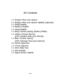
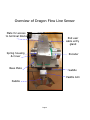
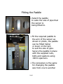
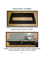
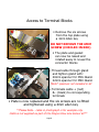
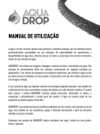
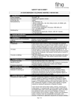
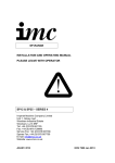
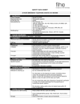
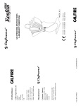
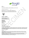
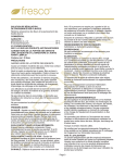
Type 4-20mA Absolute
Shaft Encoder & Optional
Flow Sensor DLS-00X
User Manual
hohner
OPTICAL ENCODERS
Hohner Corporation
5536 Regional Road 81
Beamsville,
Ontario
Canada
L0R 1B3
Canada
Tel: 1 - (905) - 563 - 4924
[email protected]
Hohner Automazione
Piazzale cocchi 10
Vedano olona (VA)
Italia
Tel: (39) 0332 866109
[email protected]
Hohner Automation Ltd
Units 14 - 16
Whitegate Industrial Estate
Wrexham,
LL13 8UG
Wales
United Kingdom
Tel: (44) - 1978 - 363 - 888
[email protected]
Hohner Eletronica Ltda
Rua João Bombo 754
Parque Itamaraty
Artur Nogueira,
São Paulo
Brasil
CEP - 13-160-000
Tel: (55) - 1938 - 77 - 5214
[email protected]
Senso Tec / Im Trade
Moscow
Tel: + 7 845 287 1346
Samara
Tel: + 7 846 373 4939
[email protected]
Hohner Elektrotechnik GmbH
Gewerbehof 1
D- 59368 Werne
Deutschland
Tel: + 49 (0) 2389 / 98780
[email protected]
Contents of this Manual
Page 3 – Kit Contents
Page 4 – Overview of Dragon Flow Line Sensor
Page 5 – Fitting The Paddle
Page 6 – Fitting Dragon Flow Line Sensor to Saddle
Page 7 – Safety notice
Page 8 – Access to Terminal Blocks
Page 9 – Changing the Tension Spring
Page 10 – Installation Drawing for CSA Certification
Kit Contents
1
1
1
1
1
1
1
1
2
1
1
1
1
x
x
x
x
x
x
x
Dragon Flow Line Sensor
Dragon Flow Line Sensor Saddle (optional)
Small Paddle
Medium Paddle
Large Paddle
Grey Tension Spring (factory fitted)
Yellow Tension Spring
(15% Weaker than grey Spring)
x Blue Tension Spring
(15% Stronger than grey Spring)
x 10mm Spanners
x 17mm Spanner
x 4mm Allen Key
x Arm Handle
x Spare Sensor Gasket
Page 3
Overview of Dragon Flow Line Sensor
Plate for access
to terminal blocks
End user
cable entry
gland
Spring housing
& Cover
Encoder
Base Plate
Saddle
Paddle Arm
Paddle
Page 4
Fitting the Paddle
• Select the paddle
to suite the size of pipe that
the sensor is
being fitted to.
Move paddle
up or down
to suit size
of pipe
• Fit the required paddle to
the arm of the sensor as
shown in photo, the paddle
can be fitted higher
or lower on the arm
to suit the size of pipe.
Secure the paddle in place
with the supplied nuts,
bolts and washers using
10mm spanners.
• The procedure is the same
for changing the paddle
size from one to another
Page 5
Fitting Sensor to Saddle
• Saddle should be welded to required pipe before
Dragon Flow Line Sensor is fitted
• Saddle is now secured to sensor with the supplied nuts,
bolts and washers using a 17mm spanner.
Page 6
Safety Notice
The cover-plate contains important certification
and safety information relating to
certification bodies
The following Page of this Instruction details how
to remove the cover-plate to access to the
terminal blocks
After end user access has been completed the
cover plate MUST be replaced to ensure the
integrity of both the product
and the certification covering the product
In the event of the cover-plate being lost the
product must not be used until a replacement
cover-plate is obtained from
Hohner Automation Ltd
Page 7
Access to Terminal Blocks
• Remove the six screws
from the top plate using
a 4mm Allen key
Remove
screws to access
terminal blocks
DO NOT REMOVE THE 6MM
SCREW (CIRCLED IN RED)
• The plate and gasket
can now be raised and
rotated away to reveal the
connector blocks
• Thread cable through gland
and tighten gland with:
20mm spanner for M16 Gland.
22mm spanner for M20 Gland.
*Note* spanners not included in kit
• Terminate cable + (red)
& - (black) to corresponding
terminals
• Plate is now replaced and the six screws are re-fitted
and tightened using a 4mm allen key
**Please Note… cable in photograph is for example only
Cable is not supplied as part of the Dragon Flow Line Sensor kit**
Page 8
Changing The Tension Spring
**It Is important that the tension spring is only changed with the
Paddle arm in the fully downward position**
Spring housing
cover retaining
screw & washer
Tension
Spring
Locating
Pin Holes
• Remove the spring
housing cover by removing
retaining screw & washer
using a 4mm allen key
• Remove the exposed
spring and fit
replacement spring of
desired tension
Yellow = 15% Weaker
Blue = 15% Stronger
• Ensuring that spring is
in recesses of both
spring housing and
spring housing cover,
twist the spring housing
cover clockwise until it
locates on the two pins.
Refit retaining screw &
washer using 4mm allen key
Page 9
Page 10