1
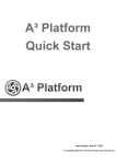
Application Guide
Connecting EZ-HMIs to Allen Bradley
Controllers Application Guide
This document will serve as a guide explaining how to connect our EZ-HMIs to an
Allen Bradley Controller. We communicate with most of the Allen Bradley drivers
available. Please follow the steps outlined in this document to configure the EZ-HMI
to communicate with an Allen Bradley Controller.
EZTouch Plus
(shown)
Serial Connection
Aug 2014
Phone: 1-563-359-7501 • www.ezautomation.net
4140 Utica Ridge Rd, Bettendorf, IA 52722
1|P a g e
Application Guide
WARNING!
Programmable control devices such as EZ Series Touch Panel are not fail-safe devices
and as such must not be used for stand-alone protection in any application. Unless
proper safeguards are used, unwanted start-ups could result in equipment damage or
personal injury. The operator must be made aware of this hazard and appropriate
precautions must be taken. In addition, consideration must be given to the use of an
emergency stop function that is in dependent of the programmable controller. The
diagrams and examples in this user manual are included for illustrative purposes only.
The manufacturer cannot assume responsibility or liability for actual use based on the
diagrams and examples.
CAUTION
Do not press the EZ Series Touch Panel touch screen with any sharp objects. This
practice may damage the unit beyond repair.
Trademarks
This publication may contain references to products produced and/or offered by other
companies. The product and company names may be trademarked and are the sole
property of their respective owners. EZ Automation disclaims any proprietary interest
in the marks and names of others.
© Copyright 2014, EZAutomation
All Rights Reserved
No part of this manual shall be copied, reproduced, or transmitted in any way without
the prior written consent of EZAutomation. EZAutomation retains the exclusive rights
to all information included in this document.
Designed and Built by AVG
4140 Utica Ridge Rd. • Bettendorf, IA 52722-1327
Marketed by EZAutomation
4140 Utica Ridge Road • Bettendorf, IA 52722-1327
Author
Thomas Bernauer
Aug 2014
Phone: 1-563-359-7501 • www.ezautomation.net
4140 Utica Ridge Rd, Bettendorf, IA 52722
2|P a g e
Application Guide
Table of Contents
Allen Bradley Drivers...........................................................................................................................................6
Driver Types ........................................................................................................................................................6
AB DF1 ............................................................................................................................................................6
AB DH485........................................................................................................................................................7
AB EtherNet/IP ...............................................................................................................................................7
AB Data Highway Plus (DH+)...........................................................................................................................7
AB Remote I/O ................................................................................................................................................7
EZ-HMI Driver Compatibility ...............................................................................................................................8
Full Featured (FS) Units: .................................................................................................................................8
Serial and Ethernet (SE): .................................................................................................................................8
Restricted (RS): ...............................................................................................................................................9
Windows Embedded (CE): ..............................................................................................................................9
EZ-Touch PLUS (EZ-T15C-E): ...........................................................................................................................9
EZ Windows 7 15” (EZW): .............................................................................................................................10
EZ3 Series (EZ3): ...........................................................................................................................................10
Communications and Wiring Pinouts ...............................................................................................................11
DH-485 ..........................................................................................................................................................11
DF-1 Full and Half duplex: .............................................................................................................................12
Remote I/O ...................................................................................................................................................14
DH+ ...............................................................................................................................................................17
Data Highway Plus for PLC5 ..........................................................................................................................20
Ethernet I/P...................................................................................................................................................22
PLC Communication Wiring Diagrams ..............................................................................................................25
Tag Addressing for SLC and MicroLogix (PLC_5) ...............................................................................................28
PLC Element strings ......................................................................................................................................28
Timers Addressing ........................................................................................................................................31
Counter Addressing ......................................................................................................................................34
Complete Address Table ...................................................................................................................................36
Address Syntax for Control Logix Ethernet/IP...................................................................................................37
Aug 2014
Phone: 1-563-359-7501 • www.ezautomation.net
4140 Utica Ridge Rd, Bettendorf, IA 52722
3|P a g e
Application Guide
Support for Arrays: ...........................................................................................................................................38
Support for Structures ......................................................................................................................................40
Support for Timer and Counter Status Bits and Flags .......................................................................................41
Steps to configure ControlLogix Tags for use with EZTouch .............................................................................42
Map tag as a PLC/SLC Message ....................................................................................................................47
Importing ControlLogix Tags .............................................................................................................................50
DRIVER ERROR CODES.......................................................................................................................................52
DF-1 Driver Errors ..........................................................................................................................................52
Remote I/O Driver Errors ...............................................................................................................................52
DH+ Driver Errors ...........................................................................................................................................52
Notes ..............................................................................................................................................................52
Technical Help................................................................................................................................................52
Aug 2014
Phone: 1-563-359-7501 • www.ezautomation.net
4140 Utica Ridge Rd, Bettendorf, IA 52722
4|P a g e
Application Guide
This page left intentionally blank
Aug 2014
Phone: 1-563-359-7501 • www.ezautomation.net
4140 Utica Ridge Rd, Bettendorf, IA 52722
5|P a g e
Application Guide
Allen Bradley Drivers
Our units communicate with most of the Allen Bradley drivers available. The list
below shows the drivers we support and PLC controllers. There are 7 different
protocols we offer as tools to communicate to MicroLogix, PLC_3&5, SLCs,
ControlLogix and CompactLogix. However, not all of them utilize the same
drivers.
Allen Bradley(AB):
A-B DF1 Half and Full Duplex (PLC-5, SLC500, MicroLogix 1000, 1200
and 1500) DH485/AIC/AIC+ for MicroLogix 1000, 1200, 1500, SLC 500,
5/01, 5/02, 5/03)
A-B Ethernet I/P (ControlLogix & CompactLogix)
A-B DF1 over EtherNet/IP (for MicroLogix & SLC 500 PLCs) A-B Data
Highway Plus (DH+)
A-B Remote I/O
Driver Types
AB DF1
This driver is an asynchronous byte-oriented protocol that uses RS232. This is
the most common protocol used by many engineers. This protocol uses a link
layer serial frame.
Full Duplex-This protocol is used for point to point link. For two way
communications between two different units or peers
Half Duplex-This protocol is a multi-drop communications with one master
and multiple slaves. It has slower data transmission but can speak to many
devices using the same port.
Aug 2014
Phone: 1-563-359-7501 • www.ezautomation.net
4140 Utica Ridge Rd, Bettendorf, IA 52722
6|P a g e
Application Guide
AB DH485
DH-485 is a proprietary communications protocol allows multiple PLC to
communicate over a network. This RS-485 uses a token passing medium access
control. This DH-485 allows connection for up to 32 devices. Communications
with other nodes within the network is achievable.
AB EtherNet/IP
This protocol is a standard industrial network and preferred network of Rockwell
automation. This protocol uses the same standard as Ethernet and TCP/IP. This
enables real time control for discrete, automatic processes, safety, drives, and high
demanding applications.
AB Data Highway Plus (DH+)
A vast majority of North American Plants still have AB's Data Highway Plus (DH+) or
Remote I/O (RIO) networks in place.
No other Touch Panel HMI manufacturer other than EZAutomation, Uticor and
Allen-Bradley can communicate over Data Highway-Plus (DH+) or Remote I/O.
DH+ uses a peer to peer communications with a Token-Passing system. The max
node allotment is 64 nodes. The communications baud rate supported are 56.7K,
115.2K, and 230.k.
AB Remote I/O
Used primarily for the PLC_3&5 controllers with its rack mounted hardware that
is very robust. This protocol is slowing being phased out by the newer line of AB
products and protocols.
Aug 2014
Phone: 1-563-359-7501 • www.ezautomation.net
4140 Utica Ridge Rd, Bettendorf, IA 52722
7|P a g e
Application Guide
EZ-HMI Driver Compatibility
This section will break down the types of drivers supported by the different EZHMIs. Some Touch Panels may support most of the Allen-Bradley drivers;
however, the Remote I/O and DH+ would require a separate option card to
support the connections and drivers.
Full Featured (FS) Units:
These units can support all serial drivers out of box, but require additional option
cards to run EtherNet/IP, DH+ or Remote I/O.
Available Drivers:
MicroLogix DF1(Full Duplex) PLC 3&5 DF1
SLC 500’s DF1 (Full Duplex)
SLC 500/MicroLogix DF1(Half Duplex)
SLC 500/MicroLogix DH-485/AIC
Available Drivers with the option card:
Data Highway Plus
Remote I/O
EtherNet/IP (FSE) supports only the inputs and outputs.
Serial and Ethernet (SE):
These units support all serial and EtherNet/IP protocols out of box. This unit does
not support DH+ and Remote I/O.
Available Drivers:
MicroLogix DF1(Full Duplex) PLC 3&5 DF1
SLC 500’s DF1 (Full Duplex)
SLC 500/MicroLogix DF1(Half Duplex) SLC 500/MicroLogix DH-485/AIC
Aug 2014
Phone: 1-563-359-7501 • www.ezautomation.net
4140 Utica Ridge Rd, Bettendorf, IA 52722
8|P a g e
Application Guide
Restricted (RS):
These units only support the serial drivers and are not compatible with our option
cards or any ethernet drivers.
Available Drivers
MicroLogix DF1(Full Duplex) PLC 3&5 DF1
SLC 500’s DF1 (Full Duplex)
SLC 500/MicroLogix DF1(Half Duplex)
SLC 500/MicroLogix DH-485/AIC
Windows Embedded (CE):
These units support all serial and EtherNet/IP protocols. In addition, these units
can be equipped with DH+ and Remote I/O cards. For the DH+ protocols, you
would need to order the unit with DH+ preinstalled.
Available Serial Drivers:
MicroLogix DF1(Full Duplex) PLC 3&5 DF1
SLC 500’s DF1 (Full Duplex)
SLC 500/MicroLogix DF1(Half Duplex) SLC 500/MicroLogix DH-485/AIC
Available Drivers with the option card:
Data Highway Plus (EH) Remote I/O Ethernet IP (EH)
EZ-Touch PLUS (EZ-T15C-E):
This is our brand new EZ-Automation drop-in replacement 15 inch HMI. These
units support most serial drivers and Ethernet IP protocols. For the DH+
protocols, you would need to order the unit with DH+ preinstalled.
Available serial Drivers:
MicroLogix DF1(Full Duplex) PLC 3&5 DF1
SLC 500’s DF1 (Full Duplex)
SLC 500/MicroLogix DF1(Half Duplex)
SLC 500/MicroLogix DH-485/AIC
Available Drivers with the option card:
Data Highway Plus (EH) Remote I/O Ethernet IP (EH)
Aug 2014
Phone: 1-563-359-7501 • www.ezautomation.net
4140 Utica Ridge Rd, Bettendorf, IA 52722
9|P a g e
Application Guide
EZ Windows 7 15” (EZW):
This is the award winning 15” WIN7 HMI. This unit support most serial drivers and
Ethernet IP protocols. For the DH+ protocols, you would need to order the unit with
DH+ preinstalled.
Available Serial Drivers:
MicroLogix DF1(Full Duplex) PLC 3&5 DF1
SLC 500’s DF1 (Full Duplex)
SLC 500/MicroLogix DF1(Half Duplex)
SLC 500/MicroLogix DH-485/AIC
Available Drivers with the option card:
Data Highway Plus/Remote I/O
EZ3 Series (EZ3):
This is our newest HMI with 64K colors and supports most serial drivers and
Ethernet IP protocols.
Available Serial Drivers:
MicroLogix DF1(Full Duplex) PLC 3&5 DF1
SLC 500’s DF1 (Full Duplex)
SLC 500/MicroLogix DF1(Half Duplex)
SLC 500/MicroLogix DH-485/AIC
Available Drivers with the option card:
Data Highway Plus
Aug 2014
Phone: 1-563-359-7501 • www.ezautomation.net
4140 Utica Ridge Rd, Bettendorf, IA 52722
10 | P a g e
Application Guide
Communications and Wiring Pinouts
Below will be examples of the communication parameters setup. You will find
these settings in the Project Information window when you first open up the
programming Software. In the PLC section to the right of the PLC model and
protocol selection area you will find a View/Edit PLC Com Setup… button. This is
where the communication parameters will be at. You will need to match these
parameters up with that of the PLC.
DH-485
The following describes the attributes that define the MicroLogix/SLC500 DH485/AIC setup. This is found in under the menu item Setup > Select PLC. Click on
the appropriate PLC type and protocol and then click on the View/Edit Attributes
button.
PLC Editor Revision: This lists the latest PLC code revision. It is useful in
determining if you have the latest PLC code software.
Baud Rate: Click on the arrow to the right of the baud rate field to
select the attribute that corresponds to the baud rate of the DH-485
network. The default is 19200.
Aug 2014
Phone: 1-563-359-7501 • www.ezautomation.net
4140 Utica Ridge Rd, Bettendorf, IA 52722
11 | P a g e
Application Guide
Panel Station Number: Enter the address for the Panel on the DH-485
network. The node address (0–31) must be unique on the network. The
default is 8.
Default PLC Station Number: Enter the default PLC address (0-31 decimal).
The address must be unique on the DH485 network. This address will be
used when a node address has not been entered in the panel internal
register map. The default for the node address is one.
Max Station Number: Enter the maximum node address for the DH-485
network. This address should be equal to or greater than the PLC or panel
with the highest node address on the network. The default is address 31.
Timeout Time (1-255 tenths of a second): Enter a time-out time between 1
and 255 tenths of a second. This is the time the panel will wait to get a
response from a PLC before it reports a time- out error. The default is 30
tenths of a second (3 seconds).
Poll Time (0-255 tenths of a second): This is the time between poll of the
PLC by the panel in tenths of a second. For constant polling set this to zero.
The default for poll time is 0 for constant polling.
DF-1 Full and Half duplex:
The following describes the attributes that define the Allen-Bradley SLC,
MicroLogix PLC with DF1 Full/Half Duplex Protocol setup. This is found in under
the menu item Setup > Select PLC. Click on the appropriate PLC type and protocol
and then click on the View/Edit PLC COM Setup button.
Aug 2014
Phone: 1-563-359-7501 • www.ezautomation.net
4140 Utica Ridge Rd, Bettendorf, IA 52722
12 | P a g e
Application Guide
PLC Editor Revision: This states the current revision of the PLC.
Baud Rate: Click on the arrow to the right of the dialog box and select the
entry that corresponds to the baud rate of the DF1 port.
Parity: Click on the arrow to the right of the dialog box and select the stop bit
number for the DF1 port. Default value is even.
Stop Bits: Click on the arrow to the right of the dialog box and select the
entry that corresponds to the stop bits of the DF1 port. The default is one.
Checksum Type: Click on the arrow to the right of the dialog box and select
the entry that corresponds to the checksum of the DF1 port. The default
checksum is BCC.
Select RS485: If the PLC is operating with RS-485 select Yes. If Yes is chosen,
control RTS is forced to Yes, controlling the RS-485 driver. This will also force
the panel to disable the receiver while the panel is driving the RS-422/485
driver.
Note: The PLC port will not work correctly at baud rates less than 9600
when RS-485 is selected.
Aug 2014
Phone: 1-563-359-7501 • www.ezautomation.net
4140 Utica Ridge Rd, Bettendorf, IA 52722
13 | P a g e
Application Guide
Default PLC Address: The default PLC station address is used when a PLC
address is not specified in a map entry. The default entry is 2.
Station Number: The station address is the address of the DH-485/RS232 DF1
module. The station address defaults to 2.
Timeout Time: Enter the time in tenths of a second the panel should wait for
communications with the PLC before displaying an error. The default for this
is 30 tenths of a second (3 seconds).
Poll Time: Enter the time in tenths of a second the panel should wait
between executing one complete sequence of reads for the current screen.
The default value is zero for constant polling.
Remote I/O
The following describes the attributes that define the PLC2, 3, and 5 Remote I/O
setup. This is found in under the menu item Setup > Select PLC. Click on the
appropriate PLC type and protocol and then click on the View/Edit PLC COM
Setup.... button.
PLC Editor Revision: This lists the latest PLC code revision. It is useful in
determining if you have the latest PLC code software.
Aug 2014
Phone: 1-563-359-7501 • www.ezautomation.net
4140 Utica Ridge Rd, Bettendorf, IA 52722
14 | P a g e
Application Guide
Baud Rate: Click on the arrow to the right of the baud rate field to
select the attribute that corresponds to the baud rate of the Remote
I/O network. The default is 57.6K.
PLC Model: Click onto the arrow to the right of the combo box to select
the model of PLC the I/O is connected to. An incorrect selection will result
in data being read from or written to the wrong rack.
Character Order in Registers: If using an ASCII object, select the character
order that is compatible with the device you are using. Select from Char 2,
Char 1 (Default) or Char 1, Char2.
Example:
Character 1-2
ABCD BADC
Character 2-1 (Default)
Rack Definitions: Click on the rack number in the list that you want to define.
Click on the Define button. The following window will appear.
The second window is separated into the four quarters of the rack. Click on
a quarter to select it. It also shows if the quarter is an active or non-active
quarter.
Aug 2014
Phone: 1-563-359-7501 • www.ezautomation.net
4140 Utica Ridge Rd, Bettendorf, IA 52722
15 | P a g e
Application Guide
Quarter Definition: This window allows for the groups and modules to be
defined for that quarter, and whether or not the quarter is active.
Active
Click on the box in front of Active if the EZSeriesTouch Panel is to be
the only I/O to respond on that quarter. If selected, the EZSeriesTouch
Panel will simulate the quarter. Do not enable if the EZSeriesTouch
Panel is to monitor only that quarter. This is to be done if there is a
real quarter or maybe another EZSeriesTouch Panel active on that
quarter. This allows for reading only that quarter — any writes will not
be returned to the PLC.
Note: The EZSeriesTouch Panel must be the only one to
respond to information for that quarter. If anything else
responds, the results could be in error.
Module 0
Group 0 0 BTR 0 BTW
Group 1 0 BTR 0 BTW
To ensure that a block transfer is handled by the EZSeriesTouch Panel, all
modules that are to have a block transfer monitored must be selected from
this screen. If data is to be transferred by a BTR from the EZSeriesTouch Panel
to the PLC it must be in an active quarter. The BTW and BTR instructions must
still be executed in the PLC logic. To select BTRs or BTWs for a quarter simply
click on all that are to be used.
Aug 2014
Phone: 1-563-359-7501 • www.ezautomation.net
4140 Utica Ridge Rd, Bettendorf, IA 52722
16 | P a g e
Application Guide
DH+
The following describe the attributes that define the DH+ setup. This is found in
under the menu item Setup > Select PLC. Click on the appropriate PLC type and
protocol and then click on the View/Edit PLC COM Setup... button.
NOTE: Tech-Support has a wonderful guide on setting up the DH+ protocol.
Please call 877-774-3279 and we will be glad to send it to you.
PLC Editor Revision: This lists the latest PLC code revision. It is useful in
determining whether or not you have the latest PLC code software.
Baud Rate: Click on the arrow to the right of the baud rate field to
select the attribute that corresponds to the baud rate of the Data
Highway Plus network. The default is 57.6K.
Panel Number (Octal values): Enter the address for the Panel on the
Data Highway Plus network. The node address (0–77 octal) must be
unique on the network. The default is 1.
Aug 2014
Phone: 1-563-359-7501 • www.ezautomation.net
4140 Utica Ridge Rd, Bettendorf, IA 52722
17 | P a g e
Application Guide
Default PLC Station Number: Enter the default PLC address (0-77 octal). The
address must be unique on the network. This address will be used when a
node address has not been entered in the panel internal register map. The
default for the node address is two.
Important Note: If connecting to a SLC500, the Station Number of the
SLC500 MUST be entered in the SLC 500 Station Number field!
Timeout Time: Enter a time-out time between 0 and 255 tenths of a second.
This is the time the panel will wait to get a response from a PLC before it
reports a time-out error. The default is 30 tenths of a second (3 seconds).
Poll Time (0-255 tenths of a second): This is the time between poll of the PLC
by the panel in tenths of a second. For constant polling set this to zero. The
default for poll time is 0 for constant polling.
SLC 500 Station Numbers: Enter the Station Number (node address) of SLC
500 PLCs that reside on the Data Highway + Network and that the Panel must
communicate with. This address should be equal to or greater than the PLC
or panel with the highest node address on the network. The Station Number
will be in Octal Values. Click on the Add button to transfer the Station
Number you have added to the list. Click on a Station Number in the list to
highlight it, and then click on the Remove button if you want to delete a
Station Number from the list. Click on OK when done.
Character Order in Registers: If using an ASCII object, select the character
order that is compatible with the device you are using. Select from Char. 1,
Char. 2 (Default) or Char. 2, Char. 1.
Example:
Character 1-2 (Default)
Character 2-1
ABCD
BADC
Aug 2014
Phone: 1-563-359-7501 • www.ezautomation.net
4140 Utica Ridge Rd, Bettendorf, IA 52722
18 | P a g e
Application Guide
Aug 2014
Phone: 1-563-359-7501 • www.ezautomation.net
4140 Utica Ridge Rd, Bettendorf, IA 52722
19 | P a g e
Application Guide
Data Highway Plus for PLC5
The following screens provide you with an example of how to set up a PLC5 with
Data Highway Plus Protocol. To set up the PLC5 with DH+ using PLC-5 Programming
Software Series A 6200, program the Channel Configuration screens as shown
below.
On the screen shown below, select DH+ to highlight, and then press F5 to access
the Channel Configuration screen.
Aug 2014
Phone: 1-563-359-7501 • www.ezautomation.net
4140 Utica Ridge Rd, Bettendorf, IA 52722
20 | P a g e
Application Guide
Configure the Channel Configuration screen as shown below.
NOTES
1) Panel baud rate must match PLC baud rate;
2) Default PLC Station Number must match PLC Node Address.
Aug 2014
Phone: 1-563-359-7501 • www.ezautomation.net
4140 Utica Ridge Rd, Bettendorf, IA 52722
21 | P a g e
Application Guide
Ethernet I/P
EZ Automation Touch Panels support communication to ControlLogix, SLC 500 series
and PLC5 over Ethernet using Ethernet IP protocol. User would need to define IP
address and PLC type for each of the PLC connected to Panel.
To select EtherNet I/P please select an HMI that support this protocol. Then on the
drop down window on PLC manufacturer please select “Ethernet Drivers”. In the
next field under “PLC Model and Protocol” please select “Ethernet I/P” as shown
below.
After selecting the Model and Protocol, on the right is the “View/Edit PLC Com
Setup…” button.
Aug 2014
Phone: 1-563-359-7501 • www.ezautomation.net
4140 Utica Ridge Rd, Bettendorf, IA 52722
22 | P a g e
Application Guide
After selecting the view/edit PLC Com Setup button, this window shown below will
appear.
This is where you will add your PLC(s) IP. You can add up to 4 PLCs at a time with
our dedicated OS. The CE HMI can handle a maximum of 64 PLCs at a time.
The EZ programming software will assign you a PLC ID for each PLC added.
Timeout Time: Enter the time in tenths of seconds that the panel
should wait for communications with the gateway to fail before
displaying an error. Default is 30 tenths of a second (3 seconds).
Poll Time: Enter the time the panel should wait between executing one
complete sequence of reads for the current screen. This time is defaulted
to 0 for constant polling.
Aug 2014
Phone: 1-563-359-7501 • www.ezautomation.net
4140 Utica Ridge Rd, Bettendorf, IA 52722
23 | P a g e
Application Guide
Please double click on the grid or press Add/Edit to enter your PLC information.
There are 3 PLCs that the panel can communicate with as shown from the dialog box
above.
Note: Entering the slot number of the PLC's CPU is only applicable for the
ControlLogix PLCs.
After entering all the necessary details, click on “Add PLC Details” to add the PLC.
You can add up to 64 PLCs for CE unit and up to 4 total PLCs for EZ Touch Jr. and SE
HMIs.
Finally, click “OK” and you are all set to communicate with added PLC/PLCs from EZ
Touch Panel over Ethernet IP.
NOTE: The SLC5/05 (DF1 over Ethernet) also works with compatible
MicroLogix PLCs.
Aug 2014
Phone: 1-563-359-7501 • www.ezautomation.net
4140 Utica Ridge Rd, Bettendorf, IA 52722
24 | P a g e
Application Guide
PLC Communication Wiring Diagrams
This section will include wiring diagrams for communications from our 15 pin port
(COM 2) to the Allen Bradley PLC.
Allen-Bradley SLC500, 5/01, /02, /03 DH-485/AIC, RS-485A
(P/N EZ-DH485)
Aug 2014
Phone: 1-563-359-7501 • www.ezautomation.net
4140 Utica Ridge Rd, Bettendorf, IA 52722
25 | P a g e
Application Guide
Allen-Bradley SLC DF1, RS-232C (P/N EZ-SLC-232-CBL)
Allen-Bradley MicroLogix 1000/1200/1500 RS232C (P/N EZ-MLOGIX-CBL)
Aug 2014
Phone: 1-563-359-7501 • www.ezautomation.net
4140 Utica Ridge Rd, Bettendorf, IA 52722
26 | P a g e
Application Guide
Allen-Bradley PLC5 DF1 RS-232C (P/N EZPLC5-232-CBL)
Data Highway Plus/Remote I/O
Aug 2014
Phone: 1-563-359-7501 • www.ezautomation.net
4140 Utica Ridge Rd, Bettendorf, IA 52722
27 | P a g e
Application Guide
Tag Addressing for SLC and MicroLogix (PLC_5)
PLC Element strings
The element strings identify where tags are mapped to in the PLC. The following
provides the Map String, Memory Type, Address Range, Flag, IO Type, Value
Type and Examples for mapping tags with the Allen-Bradley SLC’s, MicroLogix,
and PLC_5 DF1 (Full Duplex) Protocol:
O-Output: Data type discrete R/W (Word): Address range 0-255
I-Input: Data type discrete read/write (word): Address range 0-255
Aug 2014
Phone: 1-563-359-7501 • www.ezautomation.net
4140 Utica Ridge Rd, Bettendorf, IA 52722
28 | P a g e
Application Guide
B-Binary: Data type R/W (word) Address range: 0-255
N-Integer: Data type R/W or R/O (word). Address Range 0-255
Aug 2014
Phone: 1-563-359-7501 • www.ezautomation.net
4140 Utica Ridge Rd, Bettendorf, IA 52722
29 | P a g e
Application Guide
F-Float: Data type R/W or R/O (word). Address Range 0-255
Aug 2014
Phone: 1-563-359-7501 • www.ezautomation.net
4140 Utica Ridge Rd, Bettendorf, IA 52722
30 | P a g e
Application Guide
Timers Addressing
Timers can be addressed in a few ways depending on what you are trying to
accomplish. Here are some of the ways to address them using the different flags
associated with the timer instruction. The Timer instruction requires a flag address
to be programmed in EZ programming software.
The Accumulator: T4:0.ACC R/O Address range 0-255
The Preset: T4:0.PRE R/W or R/O Address range 0-255
Aug 2014
Phone: 1-563-359-7501 • www.ezautomation.net
4140 Utica Ridge Rd, Bettendorf, IA 52722
31 | P a g e
Application Guide
The Enable bit: T4:0.EN Discrete Read only
The Done Bit: T4:0.DN Discrete Read only
Aug 2014
Phone: 1-563-359-7501 • www.ezautomation.net
4140 Utica Ridge Rd, Bettendorf, IA 52722
32 | P a g e
Application Guide
The Timer Timming Bit: T4:0.TT Discrete Read only
Aug 2014
Phone: 1-563-359-7501 • www.ezautomation.net
4140 Utica Ridge Rd, Bettendorf, IA 52722
33 | P a g e
Application Guide
Counter Addressing
Counters can be addressed in a few ways depending on what you are trying to
accomplish. Here are some of the ways to address them using the different flags
associated with the counter instruction. The Counter instruction requires a flag
address to be programmed in EZ programming software.
The Accumulator: C5:0.ACC R/W Address range 0-255
The Preset: T4:0.PRE R/W or R/O Address range 0-255
Aug 2014
Phone: 1-563-359-7501 • www.ezautomation.net
4140 Utica Ridge Rd, Bettendorf, IA 52722
34 | P a g e
Application Guide
The Done Bit: C5:0.DN Discrete Read only. The .CU, .CD, .OV and .UN
members are also supported.
Aug 2014
Phone: 1-563-359-7501 • www.ezautomation.net
4140 Utica Ridge Rd, Bettendorf, IA 52722
35 | P a g e
Application Guide
Complete Address Table
Memory
Type
Access Type
Data
Type
File Range Address Range
Output (O) READ_WRITE
Word
None
0-17777 for PLC5
0-255 Micro, SLC
O:017
Input (I)
READ_ONLY
Word
None
0-17777 for PLC5
0-255 Micro, SLC
I:010
Status (S)
READ_ONLY
Word
None
0-9999 for PLC5
0-255 Micro, SLC
S:127
Binary (B) READ_WRITE
Word
B3,B9B255
0-999 for PLC5
0-255 Micro, SLC
B3:10/2
Integer (N) READ_WRITE
Word
N7,N9N255
0-999 for PLC5
0-255 Micro, SLC
N7:100
Float (F)
READ_WRITE
Word
F8-F255
0-999
0-255 Micro, SLC
F9:3
Timer (T)
READ_ONLY
READ_ONLY
READ_ONLY
READ_WRITE
READ_WRITE
Discrete
Discrete
Discrete
Word
Word
T4,T9T255
0-999 for PLC5
.EN
0-255 Micro, SLC .TT
.DN
.ACC
.PRE
15
14
13
T4:0.EN
T4:0.TT
T255:32.DN
T4:0.ACC
T4:0.PRE
Counter
(C)
READ_ONLY
READ_ONLY
READ_ONLY
READ_ONLY
READ_ONLY
READ_WRITE
READ_WRITE
Discrete
Discrete
Discrete
Discrete
Discrete
Word
Word
C5,
C9-C255
0-999 for PLC5
.CU
0-255 Micro, SLC .CD
.DN
.OV
.UN
.ACC
.PRE
15
14
13
12
11
C5:0.CU
C5:1.CD
C10:254.DN
C255:1.OV
C5:0.UN
C5:7.ACC
C5:123.PRE
Control
(R)
READ_ONLY
READ_ONLY
READ_ONLY
READ_ONLY
READ_ONLY
READ_ONLY
READ_ONLY
READ_ONLY
READ_WRITE
READ_WRITE
Discrete
Discrete
Discrete
Discrete
Discrete
Discrete
Discrete
Discrete
Word
Word
R6,
0-999 for PLC5
.EN
0-255 Micro, SLC .EU
.DN
.EM
.ER
.UL
.IN
.FD
.LEN
.POS
15
14
13
12
11
10
9
8
R6:1.EN
R6:2.EU
R255:254.DN
R6:1.EM
R10:1.ER
R11:121.UL
R6:1.IN
R6:1.FD
R44:5.LEN
R77:1.POS
String (ST) READ_WRITE
Aug 2014
Word
R9-R255
ST3-ST999 0-779 for PLC5,
SLC, Micro
Phone: 1-563-359-7501 • www.ezautomation.net
4140 Utica Ridge Rd, Bettendorf, IA 52722
Flag
Bit Example
ST3:775
36 | P a g e
Application Guide
Address Syntax for ControlLogix Ethernet/IP
Unlike PLC5 or SLC, the ControlLogix family of PLCs uses tags for its variables. To
access a ControlLogix variable, enter the ControlLogix Tag Name as the Address in
the Panel Tag Details dialog box.
Touch panel Software allows you to enter tag names that are of 40 character length,
same as the number of characters you would be allowed to enter for ControlLogix
Tag name.
A Logix5000 controller lets you divide your application into multiple programs, each
with its own data. Thus, when you create a tag, you define it as either a controller
tag (global data) or a program tag for a specific program (local data).
The general addressing format to be followed when you enter Tag Information from
ControlLogix in our Touch Panel Software:
1. Controller tags: “PLCID>"Tag Name" is the addressing format to be
followed when you enter Tag Information from ControlLogix in our Touch
Panel Software. (PLCID is the corresponding Index for each PLC
connected to the Panel)
Example: To access a controller tag "Parts_Count" in the ControlLogix
PLC, you would enter the tag address as:
1>Parts_Count
2. Program tags: "PLCID">Program:"Program Name"."Tag Name": PLCID
corresponds to the Index in the PLC configuration table from PLC
attributes. (Program name is the name of the specific program that
contains the local tag.)
Example: To access a program tag "Part Number" in a ControlLogix
PLC program called "Extruder," you would enter the tag address as:
1>Program: Extruder.PartNumber
Touch Panel Software currently supports the following data types of ControlLogix
Tags: BOOL, DINT, INT, REAL, STRING, INT (ARRAYS), DINT (ARRAYS), BOOL
(ARRAYS), REAL (ARRAYS) and Structures.
Aug 2014
Phone: 1-563-359-7501 • www.ezautomation.net
4140 Utica Ridge Rd, Bettendorf, IA 52722
37 | P a g e
Application Guide
Support for Arrays:
Touch panel Software allows you to enter tags either with one, two or three
dimensional arrays and they support address range which goes from 0 to 65535
Example of how a Tag name defined with array is addressed in our software can be
seen below:
ControlLogix Controller Tag:
Syntax: "PLCID">"Tag Name"[index]...
Example: 2>Odd[3][3]
ControlLogix Program Tag:
Syntax: "PLCID">Program:"Program Name"."Tag Name"[index]...
Example: 2>Program:Extruder.Odd[3][3]
Aug 2014
Phone: 1-563-359-7501 • www.ezautomation.net
4140 Utica Ridge Rd, Bettendorf, IA 52722
38 | P a g e
Application Guide
Rules to follow while addressing the Tags that are of Array type:
1. There should be a bracket at the beginning as well as at the end of an
address location. E.g. array[10], array[10, 10], array[10,10,10]
2. There shouldn’t be any space between the name of an array and its
address location. The correct way of addressing would be: tag1[10],
tag2[32] etc. If you enter the tag address as tag1 [10] or tag2 [3,3], it
would be an invalid tag.
3. There should be a comma (“,”) between the row and column while
addressing a two dimensional array and comma between row, column
and no of characters in terms of a 3 dimensional array. The correct way of
addressing would be : tag2[3,3],tag3[10,10,10] etc. If you enter the tag
address as tag2[3 3] or tag3[10 10 10], it would be an invalid tag.
4. There shouldn’t be any space between the row and column while
addressing a two dimensional array and similarly there shouldn’t be
any space between row, column and no of characters in terms of a 3
dimensional array. The correct way of addressing would be :
tag2[3,3], tag3[5,5,5] etc If you enter the tag address as tag2[3, 3] or
tag3[10, 10,10], it would be an invalid tag.
Aug 2014
Phone: 1-563-359-7501 • www.ezautomation.net
4140 Utica Ridge Rd, Bettendorf, IA 52722
39 | P a g e
Application Guide
Support for Structures
Touch panel software would now allow you to define tags with structures. When
you define tags of Structures, make sure that the Tag address you enter in the panel
software follows the format below:
ControlLogix Controller tag:
Syntax: PLC ID>Structure Name. Member Name
Example: 2>PROP.RTSTimer
ControlLogix Program tag:
Syntax: 2>Prop. RTS Time is an example of the addressing format to be followed
when you use
tags defined with structures in our Panel software.
Example: 2>Program:Extruder.Prop.RTSTimer
Aug 2014
Phone: 1-563-359-7501 • www.ezautomation.net
4140 Utica Ridge Rd, Bettendorf, IA 52722
40 | P a g e
Application Guide
Support for Timer and Counter Status Bits and Flags
ControlLogix Controller tag:
Syntax: “PLCID” > "Timer/Counter Name”.Flag
Example: 1> Timer1.EN
ControlLogix Program Tag:
Syntax: “PLCID”> Program:”Timer/Counter Name”.Flag
Example: 1>Program:Extruder.Counter2.ACC
Aug 2014
Phone: 1-563-359-7501 • www.ezautomation.net
4140 Utica Ridge Rd, Bettendorf, IA 52722
41 | P a g e
Application Guide
Steps to configure ControlLogix Tags for use with EZTouch
In this section will show how to configure tags to work with our HMIs. Step by
step process will walk you through the RSLogix 5000 software. You will be
creating a new tag using the Allen Bradley RSLogix 5000. You will map the tag
save and then download to the PLC.
Note: RSLogix must be Offline to create tags or to map them as PLC/SLC
Messages.
Let’s create a new tag in RSLogix 5000. While RSLogix 5000 is offline, go to LOGIC
> EDIT TAGS.
Aug 2014
Phone: 1-563-359-7501 • www.ezautomation.net
4140 Utica Ridge Rd, Bettendorf, IA 52722
42 | P a g e
Application Guide
1. Once the EDIT TAG window is open, right-click on an empty cell and chooses
EDIT TAG PROPERTIES.
2. After choosing EDIT TAG PROPERTIES the window in figure below will be shown.
Aug 2014
Phone: 1-563-359-7501 • www.ezautomation.net
4140 Utica Ridge Rd, Bettendorf, IA 52722
43 | P a g e
Application Guide
3. Give your new tag a name, for this example we have used “EZTouch_INT”.
Enter a description if needed (this is optional and not required).
4. Choose a TAG TYPE. For our purpose we will use a BASE type tag.
5. Click on the “…” box next to the DATA TYPE field to bring up the menu in Figure
4.
Aug 2014
Phone: 1-563-359-7501 • www.ezautomation.net
4140 Utica Ridge Rd, Bettendorf, IA 52722
44 | P a g e
Application Guide
7. Scroll down through the list until you come to “INT” or type “INT” into the
DATA TYPE field. The data types supported by EZTouch for use with
ControlLogix are, INT, REAL (floating pt.).
Note: The BOOL data type is not recommended for use as it may cause
unpredictable results.
8. After selecting a DATA TYPE of INT, we will need to move down and define
the ARRAY DIMENSIONS. The array dimensions define the number of
elements in your tag, ex: 100 means that you have created 100 data
elements using the INT format. You need only to fill in a value for DIM 0.
9. Once the Data Type and Array Dimensions have been
established, click OK.
Aug 2014
Phone: 1-563-359-7501 • www.ezautomation.net
4140 Utica Ridge Rd, Bettendorf, IA 52722
45 | P a g e
Application Guide
Now your NEW TAG window should look as in the example below.
To complete the creation of your new tag, select a SCOPE & STYLE. In our
example, we have defined the tag as a CONTROLLER tag. Our STYLE type is
Decimal.
Click OK to finalize the tag creation.
Aug 2014
Phone: 1-563-359-7501 • www.ezautomation.net
4140 Utica Ridge Rd, Bettendorf, IA 52722
46 | P a g e
Application Guide
Map tag as a PLC/SLC Message
1. Select LOGIC > MAP PLC/SLC MESSAGES… The window as shown below will
appear.
Aug 2014
Phone: 1-563-359-7501 • www.ezautomation.net
4140 Utica Ridge Rd, Bettendorf, IA 52722
47 | P a g e
Application Guide
2. Define a FILE NUMBER to be associated with our newly created tag. In our
example, we have used a File Number of 7.
3. Next, select the TAG NAME that you would like to associate with the File
Number 7. Here we have selected “EZTouch_INT”
4. Please complete the Mapping by clicking “OK.”
Aug 2014
Phone: 1-563-359-7501 • www.ezautomation.net
4140 Utica Ridge Rd, Bettendorf, IA 52722
48 | P a g e
Application Guide
After you click OK from the PLC/SLC Mapping window, your RSLogix 5000 screen
should look similar to the example below:
5. Save the project and download it to the PLC for the changes to take effect.
(Repeat the Tag Creation process and PLC/SLC Mapping process as needed.)
After completing the previous steps, your EZTouch will be able to access tags N7:0 –
N7:99.
Aug 2014
Phone: 1-563-359-7501 • www.ezautomation.net
4140 Utica Ridge Rd, Bettendorf, IA 52722
49 | P a g e
Application Guide
Importing ControlLogix Tags
In order to eliminate the need for having to enter the Tag Information from
ControlLogix manually, our touch panel software provides you this feature
“Importing ControlLogix Tags” through which you could Import the ControlLogix
Tags into your Touch Panel Project.
All you need to do is to Export the ControlLogix Tags from RS-Logix Software into a
CSV file and then Import the ControlLogix tags into your project in the Touch Panel
Software.
To import ControlLogix Tags from CSV file, perform the steps below:
1. Click on Import Tags -> “Import ControlLogix Tags from CSV file” as shown
below
2. You will now see the “Import ControlLogix Tags” Dialog Box
Aug 2014
Phone: 1-563-359-7501 • www.ezautomation.net
4140 Utica Ridge Rd, Bettendorf, IA 52722
50 | P a g e
Application Guide
3. Please Select the ControlLogix PLC ID from the drop down box.
4. Click “OK” and you would see the following Dialog Box notifying you of
the number of ControlLogix Tags that has been successfully imported. If
there are issues in importing the Tags, the tag database log view window
will appear to inform you of the errors.
5. Once the tags are imported, you can click on Setup > Tag Database to view
the imported Tags.
Aug 2014
Phone: 1-563-359-7501 • www.ezautomation.net
4140 Utica Ridge Rd, Bettendorf, IA 52722
51 | P a g e
Application Guide
DRIVER ERROR CODES
DF-1 Driver Errors
The values listed here may be placed in the PLC Error internal register, if the error is
detected by the EZSeries Touch Panel.
0x0001 Incompatible Revision:
This error will be displayed when the driver and exec have incompatible revision.
0x0002 PLC error incorrect map size:
This error occurs when an incompatible map is loaded into the unit. The driver will not
attempt to communicate with the PLC when this occurs.
0x0004 Limit of elements per screen exceeded:
This occurs when there are too many register on the display that can be monitored.
0x0008 PLC MSG time-out CMD=X:
This error occurs when the unit does not receive a reply to its command. The unit will retry
a command and wait for the specific time-out period before reporting this command. The
command ID causing this error is reported. CMD 0xAA=READ CMD 0XA2=WRITE.
0x0010 Invalid PLC attributes - using defaults:
This will occur if the PLC driver receives an invalid set of attributes. The default attributes
will be used when this occurs.
0x0020 PLC bad checksum CMD=X:
This occurs when a reply with an invalid checksum is received by the unit. The command ID
of the command that incurred the error is reported as part of the message. CMD
0XAA=Read CMD 0XA2=Write.
0x0040 PLC Error STS=XX EXTSTS=XX CMD=ZZ
This is reported when a controller responds to a command with an error. The error code is
shown and can be looked up in the Allen-Bradley documentation. The command ID of the
command causing the error is reported. CMD 0XAA=Read, CMD 0XA2=Write.
0x0080 PLC Nack Error
This error is reported when a controller responds to a command with a negative
acknowledgment.
0x0100 PLC element read-only
This is reported when an attempt is made to write to an element with a read-only map
entry. Read-only map entries are: input file, output file, and all discrete entries. The driver
can only read discrete entries; it cannot write to a single bit within a word.
Aug 2014
Phone: 1-563-359-7501 • www.ezautomation.net
4140 Utica Ridge Rd, Bettendorf, IA 52722
52 | P a g e
Application Guide
0x0200 PLC TX buffer full:
The error is reported if the transmit buffer becomes full in the PLC driver.
0x0400 PLC error no reply:
This occurs when the DF1 modules indicate the PLC has no reply to the last message. It is
usually displayed when the unit re-establishes communications after a PLC message timeout error. This can also occur when the panel message time-out is too short. If the PLC
message time-out does not give the PLC enough time to respond to the message this error
will be displayed.
0x0800 Error code xx:
This is reported when the PLC driver encounters an unknown error. This should never
occur.
Aug 2014
Phone: 1-563-359-7501 • www.ezautomation.net
4140 Utica Ridge Rd, Bettendorf, IA 52722
53 | P a g e
Application Guide
Remote I/O Driver Errors:
The values listed here may be placed in the PLC Error internal register, if the error is
detected by the EZSeriesTouch Panel.
Error 1: OPTION_BRD_ERROR
Screen Message: OPTION BOARD CONFIGURATION ERROR
Condition: While resetting, the card failed to load code from PROM to RAM. While
resetting, the card failed to indicate it is present and running.
While resetting, the card failed to indicate restart was successful.
Error 2: INVALID_CARD_ERROR
Screen Message: INVALID OR NO OPTION BOARD
Condition: Invalid or no card found during restart.
Error 3: RACK_ERROR
Screen Message: RACK STATUS: RACK ERROR: T: aabg-ww / bb "tag map string"
Condition: While reading or writing a tag, the PLC indicated a rack error. The PLC sees no
response from this rack in this map string.
Error 4: NO_RACK
Screen Message: NO RACK ERROR: T: aabg-ww / bb "tag map string"
Condition: When reading or writing a tag, the PLC indicated that the rack in this map string
is not present.
Error 5: PROGRAM_MODE_ERROR
Screen Message: PLC IN PROGRAM MODE: T: aabg-ww / bb "tag map string"
Condition: When reading or writing a tag, the PLC indicated that it was in program or test
mode.
Error 6: NO_WORD_ERROR
Screen Message: WORD NOT IN BTX: T: aabb-ww / bb "tag map string"
Condition: When reading from the BTX specified in the map string, the word number was
not found in the BTR, or the length of the tag element was longer than the specified BTX.
Error 7: NO_COMM_ERROR Screen Message: NO COMM ERROR
Condition: When reading or writing the Remote I/O interface card indicated that it has not
received a valid message from the PLC within a period of 160 milliseconds.
Error 8: NONACTIVE_QUARTER_ERROR
Screen Message: WRITE TO NONACTIVE QUARTER: T: aabg-ww / bb "tag map string"
Condition: When writing to the quarter specified by the group in the map string, the PLC
indicated that this quarter was not active.
Aug 2014
Phone: 1-563-359-7501 • www.ezautomation.net
4140 Utica Ridge Rd, Bettendorf, IA 52722
54 | P a g e
Application Guide
Error 9: NONACTIVE_BTR_ERROR
Screen Message: WORD NOT IN BTR: T: aabg-ww / bb "tag map string"
Condition: When writing to the BTR specified in the map string, the word number was not
found in the BTR, or the length of the tag element was longer than the specified BTR.
Error 10: NONACTIVE_QUARTER_32_ERROR
Screen Message: WRITE TO NONACTIVE INPUT QTR: T: aabg-ww / bb "tag map string"
Condition: When writing a 32 bit or string value to an Input, the value was either mapped
to a non-active quarter or out of the range for the rack specified by the map string.
Error 11: NONACTIVE_QUARTER_R32_ERROR Screen Message:
NONACTIVE_QUARTER_R32_ERROR
Condition: When reading a 32-Bit or string value from an Input or Output, the value was
out of the range for the rack specified by the map string.
Error 12: GENERAL_ERROR Screen Message: ERROR CODE xxx Condition: Never should
occur.
Error 13: INVALID_DRIVER_STATE Screen Message: INVALID DRIVER STATE
Condition: Driver reached an invalid state during a write. Driver reached an invalid state
during a read.
Error 14: LAST_ERROR
Screen Message: N/A
Condition: Never would occur.
Aug 2014
Phone: 1-563-359-7501 • www.ezautomation.net
4140 Utica Ridge Rd, Bettendorf, IA 52722
55 | P a g e
Application Guide
DH+ Driver Errors:
Error 1: INVALID_WRITE
Screen Message: INVALID WRITE TO REGISTER: oo-Nxxx::yyyy
Condition: If writing a value to a T or R and the values id greater than 0x7FFF or value is
less than 0. If writing to a T, C, or R and the value are a DISCRETE.
Error 2: MSG_TIMEOUT
Screen Message: PLC COMMUNICATION TIMEOUT
Condition: Driver timed out while waiting for a reply to a transmission.
Error 3: OPTION_BRD_ERROR
Screen Message: OPTION BOARD CONFIGURATION ERROR
Condition: While resetting, the card failed to load code from prom to RAM. While
resetting, the card failed to reach a waiting to transmit condition. While resetting, the card
failed to indicate restart was successful. While taking the card offline, the card failed to
reach a waiting to transmit condition.
Error 4: REGISTER_READ_ONLY
Screen Message: OI REGISTER IS READ ONLY: oo-Nxxx:yyyy
Condition: If writing to I or O.
Error 5: BAD_ADDRESS
Screen Message: BAD ADDRESS: oo-Nxxx:yyyy
Condition: If writing to SLC500 and the file address is greater than 255 or the word address
is greater than 255. If reading from SLC500 and the file address is greater than 255 or the
word address is greater than 255.
Error 6: COMM_ERROR
Screen Message: COMMUNICATION ERRORS
Condition: Driver timed out while waiting for a reply to a transmission. Card was not in a
waiting to transmit condition during an attempted transmission.
Error 7: STATUS_ERROR
Screen Message: STS xx EXT_STS xx ERRORS FROM PLC xx
Condition: PLC's reply to a read message returned a status error. PLC's reply to a write
message returned a status error.
Error 8: INVALID_CARD_ERROR
Screen Message: INVALID OR NO OPTION BOARD
Condition: Invalid or no card found during restart.
Aug 2014
Phone: 1-563-359-7501 • www.ezautomation.net
4140 Utica Ridge Rd, Bettendorf, IA 52722
56 | P a g e
Application Guide
Error 9: INVALID_DRIVER_STATE
Screen Message: INVALID DRIVER STATE
Condition: Driver reached an invalid state during a write. Driver reached an invalid state
during a read.
Error 10: GENERAL_ERROR
Screen Message: ERROR CODE xxx
Condition: Never should occur.
Error 11: LAST_ERROR
Screen Message: N/A
Condition: Never would occur.
NOTES:
Time-out Errors:
The time-out time specifies the amount of time the panel will wait for a reply to a message
before triggering an error. Each message sent to the PLC must be acknowledged by the PLC.
The acknowledgment must be received within a certain amount of time. If an
acknowledgment is not received, the driver will retry the message. After the message has
been sent twice with no response, the driver will report a time-out. If the panel is constantly
displaying time-out errors or communication errors, the time-out time or poll time may have
to be increased. Only the Panel is allowed to communicate with the SLC500-20, 20- or 40
series PLCs. These PLCs can only handle one or two messages at a time, and if more than
one Panel is trying to communicate, errors will occur. A panel and a program loader can be
connected to this series of PLCs without errors occurring. The amount of information being
requested from the Panel and the amount of activity on the DH485 network can affect the
response time of a message.
Discrete:
All map entries that specify a bit are read-only. The driver cannot perform bit writes. The
error "PLC Element Read-Only" is returned when an attempt is made to write to a discrete
element.
DH-485/RS-232 Interface Module Setup:
The DF1 port on the interface module should be set to match the PLC port on the panel. The
DF1 port must be set to eight bits per character. The rest of the settings must match the
settings on the panel. The panel will not be able to communicate to the module if the settings
on this port do not match the settings on the PLC port of the panel. The DF1 module must be
configured for half- duplex by selecting the DF1 protocol option from the top level setup
menu on the interface module.
Aug 2014
Phone: 1-563-359-7501 • www.ezautomation.net
4140 Utica Ridge Rd, Bettendorf, IA 52722
57 | P a g e
Application Guide
Do you still need help?
Technical Support
Most of the frequently encountered problems regarding the communications of the
AB PLCs are answered in the sections above. However, if you still need answers to
your questions, please call our technical support at 1-877-774-EASY.
Copyright © 2014 by AVG. All Rights Reserved.
Aug 2014
Phone: 1-563-359-7501 • www.ezautomation.net
4140 Utica Ridge Rd, Bettendorf, IA 52722
58 | P a g e