1
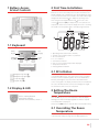
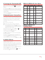
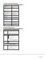
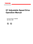
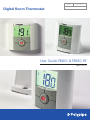
PBDIG1
Digital Room Thermostat
APRIL 2012
EFFECTIVE: 1ST APRIL 2012
User Guide PBDIG & PBDIG RF
April 2012
CONTENTS
Overview..............................................................................................................................03
1. Battery access and user controls.........................................................................................04
1.1 Keyboard ...............................................................................................................04
1.2 Displays and LED.....................................................................................................04
2. First time installation..........................................................................................................04
2.1 RF Initiation ............................................................................................................04
3. Setting the Room Temperature...........................................................................................04
3.1 Overriding Room Temperatures ..............................................................................04
4. Turning the thermostat off.................................................................................................05
5. Remote Sensor Connection................................................................................................05
6. Hidden Menus...................................................................................................................05
PBDIG & PBDIG RF User Menu.......................................................................................05
PBDIG & PRPDIG RF Installer Menu................................................................................05
7. Technical Specification........................................................................................................06
8. Fault diagnostics................................................................................................................06
02
OVERVIEW
The Digital Room Thermostat Range (PBDIG & PBDIG RF) can provide temperature
control for areas of up to 40m2.
Both units are compatible with the Remote (wet room) sensor PB23020 and
should be installed 1.2m above floor level and away from any direct heat sources.
Wiring Details are provided in the additional installer documentation.
The PBPR and PBPR RF units are designed to be used in conjunction with
our range of hardwired and wireless Master Wiring Centres and Slave Units.
Depending on the application, additional RF receivers (PB REC RF) may required.
Details on how to initiate communication with the receiver units in RF
applications are provided in the additional RF documentation.
This user guide provides user settings and Programming details, these and the
advanced settings can also be downloaded from www.ufch.com in A4 format.
03
1 Battery Access
& User Controls
2 First Time Installation
Open the two side covers and Insert the 2 AAA Alkaline supplied
batteries (or remove the small protection tab if the batteries are
already installed in the compartment). The unit will display the main
icon screen and software version number. Press and hold the right
navigational arrow button ( ) to display the opening screen.
Then using the left navigational button ( ) move the cursor
over the
and press (OK) to display the pre-set required room
temperature. After few seconds the display will revert to showing
the actual room temperature that is currently being measured.
1
2
3
4
8
5
1.1 Keyboard
6
Minus
key (-)
Plus
key (+)
Validation
key (OK)
Status
LED
7
1.Operating menu (active mode is framed)
2. Installer menu program number or parameter
3. RF Communication
4. °C or °F indicator
5. Low batteries indicator
6. Type of sensor used and temperature displayed
7. Temperature indication
8. Heating demand indication
2.1 RF Initiation
Navigation key left ( )
Navigation key right ( )
Escape key ( )
Program key ( • )
1.2 Display & LED
Red on: Heating demand
Green flash: Attention
Red flash: Error (batteries, sensor...)
On RF installations the unit must first be paired to the
corresponding RF Receiver. To do this set the receiver to pairing
mode (see receiver installation guide). Access the hidden User
Menu by following the steps as shown in the Hidden Menu
section of this guide. The display should now show menu 00 and
the code rf INI. Wait until the receiver acknowledges the signal.
The transmitter and receiver are now paired.
3 Setting The Room
Temperature
With the symbol being displayed press the Plus Key (+) to
show the current pre-set room temperature. With this display
flashing press and hold the (+) or (-) buttons until the required
room temperature is displayed.
Then press the (OK) button to save this value in the internal memory.
3.1 Overriding The Room
Temperature
At any time the current temperature setting can be increased
or decreased by simply pressing either the (+) or (-) buttons.
04
4 Turning the Thermostat Off
In order to turn off the thermostat use the navigational arrow
( ) to move the cursor over the (Off)
symbol. The display
will show the current default frost protection setting and then
switch off.
PBDIG & PBDIG RF User Menu
Menu No
Display
Description
00 (Available
on RF
Versions only)
INI
Initiates RF
Connection
01
dEG
04
no
Calibration of
temp reading
no
05
(only with
sensor fitted)
SEnC
Calibration of
sensor temp
reading
no
06
HG
Note: Whilst in the (Off) mode; if the room drops to the pre-set
frost temperature value the thermostat will automatically switch
on and maintain the temperature at the value as entered (default
setting 10.0 degC).
To adjust the frost protection default setting please see the
section headed User Menu.
5 Remote Sensor Connection
The connection of the Remote sensor allows adjacent wet rooms
to be controlled from a thermostat positioned outside the room.
However the sensor can also be used to control floor surface
temperatures where sensitive floor coverings are installed.
In the installer settings menu the sensor options are referred
to as follows.
Air = Measures room temperature
Default
Option
Refer to RF Installer
Leaflet
Temperature
Deg C
Display
Deg F
Adjustment with + or –
button (This function is
not possible for first 24
hours of operation)
Adjustment with + or –
button (This function is
not possible for first 24
hours of operation
Holiday mode
10.0C
frost setting
0.05C to 10.0C
08
CLr
Restore
factory
Default
settings
09
UErS
202
Software
Version
None
10
End
Return to
main Screen
Press OK
SEN = Remote Sensor (used to measure air temperature)
Press OK
FLr = Room temperature with floor regulation (both room
thermostat and remote sensor used) NOTE: This function
is only displayed when a Floor Low (menu 26) and a Floor
High (menu 27) value is entered.
PBDIG & PRPDIG RF
Installer Menu
To access this menu set to the unit to the Off mode
hold down the Escape key ( ) for 10 seconds.
Menu No
Display
Description
Default
Option
23
rEGU Air
See
section 4
Measures Room
Temp
Air
Sen Or Flr
24
Air t
Air Temp Reading
None
25
SEN t
Remote Sensor
Temp Reading (only
operative Is remote
sensor is used)
None (Note: If Err
display shows check
sensor
connection)
26
FL:Lo
Low floor temp
limit
no
Enter required low
temp setting
27
FL:Hi
High floor temp
limit
no
Enter required high
temp setting
28
type
Operating Mode
HYS
reG (proportional
banding)
34
CLr EEP
Restore factory
Default settings
Press OK
35
End
Return to main
screen
Press OK
then
You will then access the hidden installer menu.
The unit will display menu 23 rEGU Air.
Press (OK) to toggle between the options with the (-) and (+)
Keys and verify with OK.
If you want to choose the Flr setting use the navigation keys
to reach menu 26 (FL:L) and set the floor low value. Then scroll
to menu 27 (FL:H) and set the floor high value.
To exit the installer menu scroll to menu 35 (End) and press (OK).
6 Hidden Menus
There are 2 hidden menus which can be accessed by pressing and
holding a combination of buttons.
The user menu can be used to set a number of user preferences
such as a 12 hour or 24 hour clock display, temperature readings
in either degC or degF, etc and the installer menu can be used
to adjust various operational settings of the unit.
To access the User menu set the unit to the
and hold the ( ) button for 10 seconds.
To access the installer menu set the unit to the
press and hold the ( ) button for 10 seconds.
setting and press
mode and
05
7 Technical Specification
Measured
Temperature
Precision:
0.1°C
Environmental
Operating Temperature:
Shipping and Storage
Temperature:
0°C - 40°C
-10°C to +50°C
Setting Temperature
Range
Comfort, Reduced:
Anti freeze/OFF:
Holiday:
Timer:
5°C to 35°C
by 0.5°C step
7°C
0.5°C to 20°C
5°C to 35°C
Regulation
Characteristics:
Hysteresis of 0.5°C
Electrical
Protection:
Class II - IP30
Power Supply:
Operating Life:
2 AAA LR03 1.5V
Alkaline
2 Years
Output:
2 Points Contact (Free Contact)
Relay 5 Amps 250Vac
Optional External
Sensor:
10k ohms at 25°C
8 Fault Diagnostics
My thermostat doesn’t start
Battery
Problem
- Check if the protection sticker
on the batteries is removed.
- Check the orientation of the batteries.
- Check the charge of the batteries.
My thermostat LED, blinks in red
Problem
on Sensors
Battery level is low
The logo blinks (ambient sensor)
- Contact your installer.
The logo blinks (floor sensor).
- Check the connection
of the sensor.
- Disconnect the sensor, and check it with an ohmmeter (the value
must be around 10kohms).
The logo blinks (batteries)
- Replace the batteries.
My thermostat seems work correctly but
the temperature in the room was never
in accordance with the program
Program
- Check the clock.
- Check the difference between
Comfort and Setback temperature
is not too high?
- Contact your installer, to check
and adjust the calibration.
06
User Guide PBDIG & PBDIG RF
Digital Room Thermostat
Polypipe Building Products
Broomhouse Lane
Edlington
Doncaster DN12 1ES
Tel: 01709 770 000
Fax: 01709 770 001
2410 London Road
Mount Vernon
Glasgow G32 8XZ
Tel: 0141 778 8822
Fax: 0141 778 2703
Dromore Road
Lurgan, Craigavon
Co. Armagh BT66 7HL
Tel: 028 38 881270
Fax: 028 38 882344
www.polypipe.com
Underfloor heating systems trade website: www.ufch.com
Underfloor heating systems consumer website: www.freeyourwalls.com