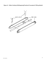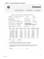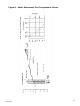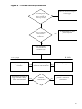
1
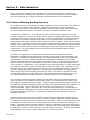
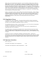
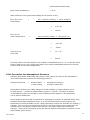
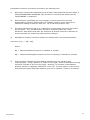
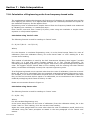
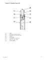
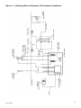
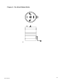
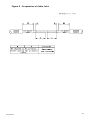
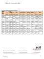
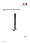
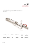
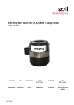
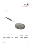
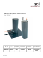
Vibrating Wire/Water Settlement Cell User Manual Man 140 3.0.2 06/08/2014 Lucie Williams Phillip Day Chris Rasmussen Manual No. Revision Date Originator Checked Authorised for Issue User Manual 1 Contents Section 1 : 1.01 1.02 1.03 1.04 1.05 Introduction ................................................................................................................................... 3 General Information ........................................................................................................................ 3 Trench Installation .......................................................................................................................... 4 Borehole Installation ....................................................................................................................... 6 Underwater Installation.................................................................................................................. 7 De-Aired Water Boiler ..................................................................................................................... 8 Section 2 : Water Circulating Unit ............................................................................................................... 9 Section 3 : Cable Jointing .............................................................................................................................. 10 Section 4 : Cable Termination ..................................................................................................................... 11 Section 5 : Data Reduction ........................................................................................................................... 12 5.01 5.02 5.03 5.04 Section 6 : 6.01 6.02 6.03 Section 7 : 7.01 7.02 Section 8 : 8.01 8.02 Factors Affecting Reading Accuracy........................................................................................... 12 Magnitude of Errors....................................................................................................................... 13 Specimen Calculation ................................................................................................................... 13 Correction for Atmospheric Pressure ......................................................................................... 14 Taking Readings and Monitoring ......................................................................................... 16 Taking Readings - Theory ............................................................................................................ 16 Taking Readings - Correct Procedure ........................................................................................ 16 Frequency of Readings ................................................................................................................. 16 Data Interpretation ................................................................................................................... 17 Calculation of Engineering units from frequency-based units. ............................................ 17 Use of Temperature Correction coefficients............................................................................. 18 Troubleshooting Guide............................................................................................................. 20 The Vibrating Wire Transducer ................................................................................................... 20 Troubleshooting with Factors other than the transducer ...................................................... 21 Figure 1 - Trench Type Cell .............................................................................................................................. 22 Figure 2 - Borehole Type Cell .......................................................................................................................... 23 Figure 3 - Vibrating Wire Settlement Cell System Installation ......................................................... 24 Figure 4 - De-Aired Water Boiler ................................................................................................................... 25 Figure 5 - Preparation of Cable Joint ........................................................................................................... 26 Figure 6 - Cable Jointing Kit Wrapping Electrical Connector & Fitting Mould ............................. 27 Figure 7 - Sample Calibration Certificate ................................................................................................... 28 Figure 8 - Water Settlement Cells Temperature Effects ...................................................................... 29 Figure 9 - Trouble Shooting Flowchart ....................................................................................................... 30 Figure 10 – Conversion Table ......................................................................................................................... 31 User Manual 2 Section 1 : Introduction This instruction manual describes the techniques required for borehole or trench installation of the water filled vibrating wire settlement cell. The operating principle and method of reading using commercially available vibrating wire readout equipment is briefly discussed. For a complete description of the use of the readout or datalogger used, please see the appropriate manual for that instrument. It is essential that the equipment covered by this manual should be installed and operated by competent and suitably qualified staff. The techniques described for installation of the cell are intended to serve as a general guide and will vary to suit particular site conditions. 1.01 General Information Description The vibrating wire/water settlement cell is installed at the required measuring horizon and is connected to the monitoring station by an electric cable for the vibrating wire signal and a pair of small bore nylon tubes for the water. The instrument readout point must be built on stable ground beyond the influence of any expected movement or surveyed accurately and regularly to quantify any movement it is suffering. The readout point provides a datum from which all readings are referenced. The cell consists of a vibrating wire pressure transducer with an integral liquid chamber. The twin nylon tubes are filled with water and connected at one end to the water level datum pot and at the other to the transducer liquid chamber. Vertical movement of the cell relative to the datum pot at the control house results in a corresponding change in liquid pressure at the transducer. Readings are taken using a vibrating wire readout unit connected to the cable via a suitable terminal unit. Alternatively, for multiple vibrating wire instrument installations cables may be terminated at automatic data logging equipment. The system is suitable for either trench or borehole installation. The trench type settlement cell is 115mm diameter, 370mm high and mounted on a 300mm square base plate and the borehole type is 155mm diameter, 340mm high, with a left hand threaded connection to receive a special placing adaptor. The system is reliable, simple to install and to read. Measurements are taken remotely from the readout point and because cells are buried they do not interfere with the construction progress after instrument installation. The liquid tubes allow for re-circulation of the water after installation and for in-situ instrument checks/calibration. The settlement cell must be installed at a level lower than the liquid datum pot at the monitoring station and the difference in elevation between the two points must be within the cell operating range, with due allowance made for anticipated vertical ground movement. The reading range and accuracy of the cell is determined by the range of the transducer fitted. In installations that involve datum pot open to the atmosphere, a correction for atmospheric User Manual 3 pressure will be needed. An accurate barometer is therefore necessary for this. In installations where water lines, transducers or both will be subject to temperature variations, corrections for temperature variation will be required. Installation Techniques The installation procedures outlined in this text are intended as a general guide and flexibility in the interpretation of them is required to suit particular local site conditions. The three main methods of settlement cell placement are trench installation, borehole installation and underwater installation. Each is described separately below. 1.02 Trench Installation The settlement cell terminal/datum panel should be rigidly fixed to the wall of an instrument house or cabinet located on stable ground beyond the zone of any anticipated ground movement. The cable and water line tubing are cut to length and bound together at intervals along their length using adhesive tape, the colour of which identifies a particular instrument. A trench is excavated from the terminal location to the cell installation point and the cable and twin tubes laid in the trench, connected to the respective fittings within the cell and on the terminal/datum panel, and tested. The water level in the datum pot provides the datum to which all readings can be related. The cell is then placed horizontally on compacted material or, alternatively, cast inside a concrete block, and the trench carefully backfilled and compacted. (a) Confirm with the Engineer the required installed locations of the cell and terminal point, in both plan and elevation, and ensure that the elevation difference between the two plus the anticipated settlement is within the instrument operating range. Calculate the tubing and cable lengths required for proposed trench route. Agree and record the master colour code system to provide identification for each settlement cell. (b) Construct the instrument house or cabinet on stable ground, preferably beyond the influence of any anticipated ground movement and rigidly fix the terminal/datum panel in a vertical position to one wall. (c) Cut the cable and water line tubing to length. Up to 10% over the exact calculated length should be allowed to accommodate snaking the cable in the trench, ground movements, and cutting the cable back at the instrument and terminal points. Seal both ends of each tubing using adhesive tape to prevent entry of dirt, etc. Working to the previously agreed master colour code, individually identify the instrument by binding the cable and tubing together at intervals with the respective colour of adhesive tape supplied for the purpose. For positive identification at the tubing ends colour code at 1m intervals over the final 3m. (d) The trench cross-sectional dimensions will be dependent upon such factors as the number of instruments involved and the type of parent material through which the trench will be excavated. Each particular site situation should be individually considered in these terms but with the common denominator that effective protection of the buried tubing is essential. Excavate the trench from terminal location to cell installation point and ensure that the trench invert is smooth, with no undulations, and of constant gradient along its length. Place a layer of compacted sand or stone-free material in the trench to a depth to provide adequate tubing protection and compact. User Manual 4 (e) With reference to FIGURE 1, connect the cell to the cable and water line tubing as follows. Loosen the two gland nuts (3) to free the cable tail (1). Remove the two screws (4) and part the cell outer case tube (5) from the base plate (8). Withdraw cable tail (1) from inside the cover tube through gland. Remove screws (9) from top of cover tube to release the vibrating wire transducer (6). Prepare the water line (2) by carefully removing the outer polythene sheathing to expose the two tubes within over sufficient length to reach comfortably from the gland nut (3) to the fittings (7). To prevent kinking ensure that when reassembled the tubes will describe gradual curves over their length within the cell. Connect the tubes each to one compression fitting (7). It does not matter which tube is connected to which fitting. Re-assemble the cell. (f) The electrical cable and twin water line tubing should now be snaked along the base of the trench and into the instrument house. The trench should not be backfilled until the final zero reading has been established. (g) With reference to FIGURE 3 connect the water line tubing to the terminal panel, carefully remove the outer polythene sheathing to expose the two tubes over a sufficient length, so that they reach comfortably between the tube ducting and the manifolds. From each settlement cell usually the clear tube is connected to the return manifold so the water can be seen returning through the line. (h) Fix a permanent length of tubing to the supply manifold, long enough to reach the water circulating unit. Connect the de-aired water boiler, the vacuum pump and the pressure pump to their respective positions on the water circulating unit. (i) Open the necessary valves and draw de-aired water from the boiler to completely fill the cylinder of the water circulating unit using the vacuum pump. Close all valves. Open the necessary valves and apply pressure to the bladder within the cylinder using the pressure pump. This in turn will pressurise the water in the circulating unit. Close all valves. For full details of how to use the De-aired Water boiler and Water Circulating Unit refer to Sections 3 and 4. (j) Open the necessary valves to allow water to flow from the cylinder to the water supply manifold, through the respective manifold valve into the water line tubing to the cell, back to water return manifold and into the datum pot. Continue until the datum pot is filled to the overflow level. Close the valve at the top of the water return manifold. (k) Water should now be circulated through the tubing before the zero reading is taken. A quantity of water equal to 5 times that contained in the tubes should be circulated around the system to comprehensively flush out any air prior to commissioning. A length of tubing should be attached to the return manifold bottom valve and as the water returns through this tube, it should be plunged to the bottom of a clear container partly filled with water. Doing this will allow any air that comes out of the tube to be identified as a bubble that rises from there turn tube. Also, the container can be used to measure the volume of water that has already been circulated. (l) Zero Readings A zero reading is now obtained using the Vibrating Wire Readout/Logger. In the case of a trench installation, the cell should be covered over with a mound of material at least 1 metre high and left for at least two hours before the zero can be taken. This is to ensure the transducer is at a stable temperature and not exposed to the sun or cold winds. A change in temperature of the transducer will cause a change in period reading, all other variables remaining constant. Before the final zero reading is established, it is preferable to monitor the cell over the course of a few hours to confirm zero period stability. User Manual 5 It is also essential now to accurately record the “base” atmospheric pressure (in cmH20) at the moment the base period is recorded. Most barometers measure the pressure in millibars which can be considered equal to cmH20 to a suitable degree of accuracy. (m) With a zero reading established, the trench is now be backfilled with stone-free material and compacted. (n) With the trench backfilled and compacted, check the zero reading. 1.03 Borehole Installation The settlement cell terminal/datum panel should be rigidly fixed to the wall of an instrument house or cabinet located on stable ground beyond the zone of any anticipated ground movement. If this is not possible, the control house should be levelled regularly to quantify any movement occurring. The cable and water line tubing are cut to length and bound together at intervals along their length using adhesive tape, the colour of which identifies a particular instrument. The twin tubes are connected to the respective fittings within the cell and on the terminal/datum panel, and tested. The water level in the datum pot provides the datum to which all readings can be related. A borehole is formed to the depth at which the cell is to be placed and a trench excavated from the top of the borehole to the terminal location. Grout is placed at the borehole base to form a plug and the cell is pushed into the grout using a placing adaptor and placing tubes. The installing equipment is disconnected from the cell and the borehole backfilled with weak grout or granular material. The cable and tubing are laid in the trench which is carefully backfilled and compacted. (a) Confirm with the Engineer the required installed locations of the cell and terminal point, in both plan and elevation, and ensure that the elevation difference between the two plus the anticipated settlement is within the instrument operating range. Calculate the total tubing length required for proposed trench route and borehole depth. Agree and record the master colour code system to provide identification for each settlement cell. (b) As described in 2(b) - (d) but referring to FIGURE 2. (c) Form borehole, minimum diameter 150mm to required cell installation depth. (d) With reference to FIGURE 2, as described in 2(d). (e) With reference to FIGURE 3, as described in 2(e) - (g). (f) With reference to FIGURE 2, as described in 2(h). (g) The borehole depth is governed by the instrument operating range from 0.5m to the range of the vibrating wire transducer fitted and therefore it is necessary to select length of placing tubes required for installation. Connect placing adaptor to placing tube, and tighten. Using a measuring tape and starting from the top of the placing adaptor, mark level corresponding to ground level for the proposed installation depth with a band of coloured adhesive tape (after having taken due allowance for the distance from the placing adaptor to the pneumatic transducer). (h) Place stiff grout to the borehole base over sufficient depth to cover the cell (minimum 400mm). User Manual 6 (i) The placing adaptor and receiving hole in the cell are fitted with left-hand threads. By turning in an anticlockwise direction screw the placing adaptor and attached placing tube into the cell. Carefully lower down the borehole, assembling placing tubes in the previously marked sequence. Push the cell into the grout plug until the previously measured ground level mark corresponds to actual ground level. Throughout ensure that no tension exists in the cable and tubing. Unscrew the placing adaptor from the cell by rotating the placing tubes in a clockwise direction and remove all placing tubes from the borehole. (j) Make a final check to ensure cable continuity and water circuits are leak-free, as described above. (k) Backfill borehole with weak grout or granular material to trench invert. The procedures described in Section 2 should now be followed in order to carry out the following tasks: 1) Snaking of tubing and electrical lines along the base of the trench. 2) Circulation of de-aired water through the tubing prior to commissioning. 3) Establishment of zero reading. 4) Checking of zero reading after trench backfilled and compacted. 1.04 Underwater Installation The settlement cell terminal/datum panel should be rigidly fixed to the wall of an instrument house or cabinet located on dry land beyond the zone of any anticipated ground movement. If this is not possible, the control house should be levelled regularly to quantify any movement occurring. The cable and water line tubing are cut to size and bound together at intervals along their length using adhesive tape, the colour of which identifies a particular instrument. The twin tubes are connected to the respective fittings within the cell and on the terminal/datum panel, and tested. The water level in the datum pot provides the datum to which all readings can be related. Cell installation is by lowering from a boat or direct hand-placement by divers. Finally, the cell cable and tubes (along their submerged length) are carefully anchored to the sea/river bed until fill is hydraulically placed to hold them permanently in position. It is not realistic to attempt to state a precise underwater installation procedure due to the considerable variety of possible site conditions that influence the choice of method. However, the main points are discussed below and should be included in any adapted procedure used to suit the conditions of a particular site. (a) Confirm with the Engineer the required installed locations of the cell and terminal point, in both plan and elevation, and ensure that the elevation difference between the two plus the anticipated settlement is within the instrument operating range. Calculate the cable and tubing lengths required for the proposed route. Agree and record the master colour code system to provide identification for each settlement cell. (b) Construct the instrument house or cabinet on dry land beyond the zone of any anticipated ground movement and rigidly fix the terminal/datum panel in a vertical position to one wall so that the future reduced level of mercury within the datum pots will be as specified by the Engineer. User Manual 7 (c) As described in 2(c). (d) As described in 2(e) - (j). (e) Install the cell. If there are soft sediments on the sea/river bed they should be removed by dredging down to a more competent foundation material before commencing instrument installation. While it is possible to install the cell remotely by lowering from a boat it is more convenient and thorough, and therefore recommended, to use a diver for direct hand placement. (f) Snake the cable and tubing and carefully place stone-free material around and above to such a depth as to provide adequate protection. (The degree of snaking will be dependent upon the magnitude of the expected ground movement. Where the cable and tubing crosses the interface between two dissimilar fill materials, across which differential settlement is expected, it is important that the degree of snaking should be locally increased.) With reference to 2(d) and (m), the cable and tubing should be trenched up the shore to the monitoring point so that exposure to wave action is kept to a minimum. (g) De-aired water can now be circulated and zero readings established as described in 2(k) and 2(l). 1.05 De-Aired Water Boiler Refer to figure 4. Up to 50 litres of de-aired water can be prepared in the boiler at one filling. An immersion heater coil heats the water to boiling thus expelling any air or gases in solution. By sealing the boiler and allowing it to cool, the steam and water vapour above the water condense thus creating a partial vacuum inside the boiler. This prevents further solution of air or gases. (a) Remove the central filler-cap using the special spanner provided. Open valves V and S. (b) Pour in clean water to within 100mm of the top. (c) Connect the electrical cable to a suitable mains supply (either 110V or 230V as indicated on the immersion heater coil cover). Switch on at the mains. Bring to the boil and allow to boil for fifteen minutes. Switch off at the mains supply and disconnect plug from wall socket. (d) Close Valves V and S and replace the central filler-cap. Allow to cool. WARNING: NOTE: Although the cap is fitted with a pressure relief valve, never boil with the filler-cap on. With a partial vacuum inside the boiler, never open valve S before opening valve V, as this will draw air into the de-aired water. SAFETY REQUIREMENTS: The 4 psi Pressure Relief Valve in the centre of filler-cap must be checked at intervals not exceeding 12 months by a competent person. User Manual 8 Section 2 : Water Circulating Unit Refer to figure 3. Operating instructions for drawing de-aired water from the boiler and filling water-line tubing and settlement cells are as follows:(a) Close all valves. (b) Attach vacuum pump to valve B with black hose, open valve B and A, remove air from inside bladder. (c) Close valve B and remove hose and fit on valve A. (d) Fit red hose to valve D and place end of hose in water. Pump vacuum pump to draw water into circulating unit. Avoid drawing air. (e) Close valve D and A. Fit foot pump to valve E and attach nylon tube to valve C and terminal panel left-hand side lower valve. (f) Open valve C of water circulating unit. Open the bottom valves on the left and right valve panels - these are the inlet and outlet valves for the circulating water. Now open inlet and outlet valves for the cell to be de-aired. All other valves should be closed. (g) Make sure top valves leading to the datum pot are closed. Start to pump water with the foot pump. Do not go above 2.5 bar or the range of the cell, whichever is the least. During circulation, the outlet valve should have a tube attached (which can be permanently left in place) which should be plunged to the bottom of a clear container partly water filled. Any air expelled from the tubes will appear as a bubble which rises from the tube. (h) Repeat steps (a) to (g) as necessary to de-air/circulate for all cells. User Manual 9 Section 3 : Cable Jointing Refer to figures 5 and 6. It is desirable to minimise cable joints, but where they are unavoidable a joint kit may be supplied. The effectiveness of this joint largely depends on the care with which the jointing operation is carried out. (a) Thoroughly scrape all wax and dirt from cable end for approximately 150mm. Prepare the cable ends as shown. Stagger the individual conductor connections. (b) Use the crimped connectors to join the conductors. Ensure electrical continuity of outer armoured screen is re-established across joint. Use the electrical insulation tape to wrap the connectors. Stretch the tape to half its original width and apply one layer half lapped over connector area only. Do not wrap the tape beyond the pencilled area. (c) Trim the ends of the mould with a sharp knife to suit the diameter of the cable. Hold the mould halves in place centred over the splice. Snap both halves together and fit the pouring spouts in the holds. Ensure that both seams are completely snapped together. Tape the ends of the mould body to form a seal. (d) Mix the resin thoroughly and maintaining the mould in a level position, spouts uppermost, pour the resin through one spout until both spouts are completely filled. When the resin has solidified and cooled remove the spouts. NOTE: User Manual In cold weather (below 15 degrees C) the resin becomes very viscous. It is therefore advisable to keep the resin in a warm place prior to mixing. Mix the compound until its temperature starts to rise, this decreases the viscosity. 10 Section 4 : Cable Termination The cables are normally terminated in terminal boxes. The cables enter through waterproof glands. (a) Unscrew the cover or open the lid as appropriate. Unscrew the fixing screws holding the terminal panel and carefully remove it without straining the internal connecting leads. (b) Prepare the cables by stripping and cutting back 20mm approx. of the outer insulation and armour. Remove the rubber packing and strip back 5mm of the conductor insulation. (c) Slacken the entry glands and insert the cables. Make connections to the contact block (details of colour coding supplied with each instrument). Retighten the glands to grip the cables. (d) Replace the terminal panel and secure. Connect the Vibrating Wire Readout/Logger to each instrument in turn to check connections User Manual 11 Section 5 : Data Reduction Figure 7 shows an example of the vibrating wire instrument calibration certificate as supplied with each vibrating wire instrument. The form is designed to provide complete site record facilities for a single instrument and its application is self explanatory. 5.01 Factors Affecting Reading Accuracy The reading accuracy of vibrating wire/water settlement cells is influenced by the effect of temperature changes on water density. Where large seasonal or daily temperature fluctuations occur then due arithmetic allowance of this must be made when calculating elevation differences between the datum level and the installed settlement cell. Consider the installed cell. It is connected to the remote monitoring point by the twin tubing, containing the continuous water column, with the tubing installed within trenches over their entire length to the terminal point. In all but exceptional circumstances the soil temperature will remain constant at the depth of the trenched tubing and therefore the temperature of the water contained within will also remain constant. There will be minimal reading errors. However, for maximum reading accuracy attention should be given to that portion of the tubing length which is exposed to ambient air temperature at the monitoring station, particularly when no means of temperature control is provided (eg. heating or airconditioning). The worst effects will arise from large vertical heads subject to large temperature variations. The effect of temperature on reading accuracy becomes more significant with the underwater installations required during causeway construction or land reclamation, for example. For shallow and sheltered water, the water temperature will vary considerably with weather or season, causing corresponding temperature fluctuations in the water column contained within the twin tubes lying on the bottom. Changes in temperature will alter the water density and consequently the pressure exerted on the diaphragm of the cell's transducer. Additionally in such situations the monitoring station is often constructed on a platform founded on piles extending above maximum water level. Normally it is not possible to equip the monitoring station with any form of temperature control. That part of the twin tubing length above water level will be subjected to ambient air temperature. Where single skin metal terminal enclosures are used or the tubing is exposed to direct sunlight, temperatures considerably higher than ambient shade temperatures can occur. The combined effect of the three factors on reading accuracy can be considerable. The correction method required to obtain accurate data under the conditions described above is outlined in the Specimen Calculation below. It is important that no part of the twin tubing is exposed to direct sunlight. Tubing leaving the monitoring station platform to the installed instrument should be positioned within the natural shadow of the platform. It may be necessary to place the tubing within a freely-ventilated cover to provide a continuous shade. Also, to determine air, water and soil temperatures it is advisable to install a screened, perforated access tube vertically through the monitoring station floor to the lake or sea bed soil beneath. Temperature readings can then be taken at various depths as required. Experience has also shown that to obtain accurate data it is absolutely essential that no part of the instrument system is allowed to move or vibrate during the reading operation. To eliminate this possibility, two precautions are necessary. Firstly, connecting tubing from the installed instrument to the monitoring point should be firmly anchored throughout its length. The most critical areas are where the tubing is subjected to wave and wind action at and immediately above the water surface. Secondly, the monitoring station itself should be sufficiently strong to resist movement induced by wave and wind. If this is not possible then readings should only be taken when there is no such movement. User Manual 12 Water purity may sometimes be important. At 4°C the density of fresh water relative to distilled water is 1.0011. This represents a reading error of approximately 2cm on a 20m water head. However, as the water used in a practical installation is likely to be derived from the same source throughout its useful life, such an error will be constant and would therefore not affect the accuracy of reading differences, i.e. settlement. This assumption is valid when very small proportions of water treatment chemicals are present - it may not be valid in some tropical areas where chemical additives vary in both quantity and quality. Advice should be sought from the local water authority or, failing this, only distilled water used throughout the instrument system. Finally, it may also be useful to take readings at the same time each day. Direct sunlight effects are minimal in the early morning. Also, much of the overnight temperature, which is relatively stable and predictable, will remain within that portion of the water column subject to ambient air temperature variations, thus reducing the possibility of significant temperature gradients in that portion of the tubing assumed to be at the same temperatures. 5.02 Magnitude of Errors To illustrate this, refer to FIGURE 8. The graph shows the effect of water temperature variations on a 20m high water column related to a readout device assumed to be totally accurate over the considered temperature range (0 to 40°C). Two important points are evident. Over the range of 0 to 10°C errors due to temperature variation are minimal and can normally be ignored. The effect is considerable over the range 10 to 40°C and must be compensated for if meaningful data are to be obtained. The graph tends to oversimplify the problem since it assumes that the entire 20m water column is subjected to the same temperature at any given time. This assumption is not valid if the water column is subjected to the differing soil, water and air temperature along its length. Consider the case of an underwater installation as described earlier. Both the air temperature and the surrounding water temperature will affect the water within the tubing. The correction to the data must be applied in two parts corresponding to the effect of each particular temperature on the respective length of water column over which it has direct influence. 5.03 Specimen Calculation Refer to figure 8. Total water head subject to air temperature = 4m. Total water head subjected to water temperatures = 16m. Total water head = 20m. = 25°C (Taken insider User Manual 13 perforated/screened tube). Mean water temperature = 21°C. With reference to the graph and relating all corrections to 4°C. Error due to air = 4m (column in the air) x (Error at 25°C) temperature 20m (test column) = 0.2 x 60 = 12mm Error due to water temperature = 16m (column in water) x (Error at 21°C) 20m (test column) Total error on = 0.8 x 40 = 32mm = 12 + 32 20m head = 44mm Therefore 44mm must be added to the reading to standardise at 4°C, i.e. to read the same head of water at 4°C you would need 44mm more water head added because the column would shrink at the lower temperature. 5.04 Correction for Atmospheric Pressure Vibrating Wire Water Settlement Cells have a water datum pot open to the atmosphere. This means that they measure the following pressure: Pressure Measured = Head of Water in twin tubing + Atmospheric Pressure acting on Datum Pot Atmospheric pressure can easily change from 980 millibars to 1020 millibars over a 24 hour period. 1 millibar is approximately equal to 1 cmH20. Therefore a change in atmospheric pressure from 980 to 1020 millibars would register on the settlement cell as a 40cm settlement. It can therefore be seen that a correction for atmospheric pressure is essential when using Vibrating Wire/Water Settlement Cells. It is recommended that for this purpose, two barometers be made available on site. Both barometers need to be accurate to1 millibar (1 cmH20). Prior to using the barometers to derive correction factors, they should each be monitored for a few days to ensure that they give the same magnitude of pressure changes. (They need not both be giving the correct absolute atmospheric pressure or even both reading equal values). User Manual 14 Atmospheric pressure corrections are made in the following way: 1) Once each cell has been backfilled over and water tubes filled with de-aired water, a “BASE ATMOSPHERIC PRESSURE” (Bp) should be recorded at the same time the “BASE PERIOD” is measured. 2) One barometer (preferably the most rugged) is carried around the site and anatmospheric pressure reading taken in millibars (cmH20) at the same time a settlement reading is taken for each cell. Let us call this pressure “Mp”. 3) The other barometer is kept in an “impact free” environment such as on the wal lin the site office. The “site barometer” should be checked against this “office barometer” both before and after site visits and at random intervals in between to ensure that both are measuring equal pressure changes. 4) Atmospheric Pressure Correction Factors are determined in the following fashion: Correction (cm) = [Bp - Mp] Where: Bp = Base Atmospheric Pressure (in millibars or cmH20). Mp = Measured Atmospheric Pressure at time of reading (in millibars or cmH20). 5) User Manual This correction is added onto the reading obtained from the vibrating wire readout/logger. Using a positive “K” factor in the logger, leads to settlement causing a positive increase in value on the logger. Similarly, an increase in atmospheric pressure causes an “apparent settlement” of the cell. For this reason, it can be seen that pressures higher than Base Pressure give rise to negative (“heave”) corrections. 15 Section 6 : Taking Readings and Monitoring 6.01 Taking Readings - Theory Vibrating Wire Settlement Cells can be read with Soil Instruments Vibrating Wire Readout/Logger or any other readout capable of reading a vibrating wire transducer. The wire of the sensor is excited to oscillate at its resonant frequency which is then accurately measured by counting the number of oscillation cycles. The reading can be obtained from the readout/logger as raw data in terms of normal reading (Period x 107) or linear reading (f²/1000). If a readout/logger channel is dedicated for one particular instrument and a Channel Table set up (refer to logger user’s manual) for that channel, the readings can be obtained and logged/stored in the readout/logger memory directly in cmH20. It is extremely important to establish a reference reading (or “base” reading) at the time of installation and initial setting up. Store this reading for zero displacement with gauge factor for a particular cell. The logger will display positive displacement for increasing settlement if a positive gauge factor is inputted into the logger. 6.02 Taking Readings - Correct Procedure Following the procedure given below should mean random errors are avoided when taking measurements of the cells: 1) Select correct channel on readout/logger. 2) Select correct number on dial of terminal panel. 3) Close all valves of instruments NOT being used. 4) Check water level in datum pot - if low, top up with de-aired water. 5) During reading, the logger should be allowed to “ping” at least 3 or 4 times on each instrument to ensure stability. 6) Record Atmospheric Pressure at time of reading. 6.03 Frequency of Readings The frequency with which readings of the Vibrating Wire/Water Settlement Cell are taken will depend on the stage of construction and the behaviour of the structure after completion. The following points are relevant: 1) Immediately after installation it is a good idea to take readings as frequently as twice daily for a few days to confirm zero readings. 2) During the general construction phase of the project, a normal reading frequency would be once or twice a week. 3) After completion of the structure, the frequency with which readings are taken may be set at every two weeks or even less. If an increased rate of change in the readings is observed, then it may be necessary to increase the frequency with which readings are taken in order to properly record any movement taking place. User Manual 16 Section 7 : Data Interpretation 7.01 Calculation of Engineering units from frequency-based units. The mathematical relationship between the frequency of vibration of a tensioned wire and the force applying the tension, is an approximate straight line relationship between the square of the measured frequency and the applied force. Engineering units of measurement maybe derived from the frequency-based units measured by vibrating wire readouts, in 3 traditional ways:From ‘Period’ units and from ‘Linear’(f^2/1000) units using two methods: a simple Linear equation or a Polynomial equation. Calculation using ‘Period’ units The following formula is used for readings in ‘Period’ units. E = K (10^7/P0^2 – 10^7/P1^2) Where; E is the Pressure in resultant Engineering units, K is the Period Gauge Factor for units of calibration (from the calibration sheet), P0 is the Period ‘base’ or ‘zero’ reading P1 is the current Period reading. This method of calculation is used by the Soil Instruments Vibrating Wire loggers’ (models RO-1-VW-1 or 2 and with serial numbers starting VL or TVL) internal processors’, for calculating and displaying directly on the loggers’ LCD screen, the required Engineering based units. The loggers’ require ‘Period’ base or zero reading units for entering into their channel tables, to calculate and display correctly the required engineering units. If an Engineering-based unit is required other than the units of calibration, then the correct K factor will have to be calculated using the standard relationship between Engineering units. For example, if the units of calculation required were in mH2O and the calibration units were kPa, we can find out that 1kPa is equal to 0.1022mH2O, so we would derive the K factor for mH2O by multiplying the K factor for kPa by 0.1022. Please see conversion factors in Figure 10. Calculation using Linear units The following formula is used for readings in ‘Linear’ units. E = G (R0 – R1) Where; E is the resultant Engineering unit, G the linear Gauge factor for the units of calibartion (from the calibration sheet), R0 is the Linear ‘base’ or ‘zero’ reading, R1 is the current Linear reading. Again the Linear gauge factor for units other than the units of calibration would need to be calculated using the same principles as stated in the last paragraph of the ‘Period unit’ section. User Manual 17 Linear unit calculation using a Polynomial equation Linear units maybe applied to the following polynomial equation, for calculation of Engineering units to a higher order of accuracy. E = AR1^2 + BR1 + C Where; E is the resultant Engineering unit, A, B and C the Polynomial Gauge factors A, B and C, from the instrument’s calibration sheet, R1 is the current Linear reading. The value C is an offset value and relates to the atmospheric pressure experienced by the piezometer at the time of calibration. This figure will have changed at the time of installation due to changes in altitude or barometric pressure, so C should be re-calculated at the installation time as follows: C = - (AR0^2 + BR0) Where; A and B are as above, R0 is the Linear ‘base’ or ‘zero’ reading. Please note that the sign of the re-calculated value of C, should be the same as the original value of C, so if the original is negative then the recalculated value should also be negative. Conversion to engineering units other than the units of calibration, would best be done after conversion, using a factor calculated using the same principles as stated in the last paragraph of the ‘Period unit’ section. Please see conversion factors in Figure 10 7.02 Use of Temperature Correction coefficients. Soil Instruments vibrating wire transducers have been carefully developed over many years, so that the combination of material types in the instruments’ build, its design and the manufacturing processes, results in instruments which are little affected by changes in temperature. Any changes are regarded as insignificant. Therefore, as standard, Soil Instruments vibrating wire instruments are not provided with temperature correction coefficients, even though they may be specified with a thermistor. It should be noted that while an instrument is changing temperature, the stresses created across the transducer body by temperature gradients, will induce changes in the instruments reading, but once the instrument has stabilised at its new temperature, these differences will disappear. The time for an instrument to fully stabilise at a new temperature will be in the order of 30 to 40 minutes. At the time of ordering, instruments may be specified, calibrated with individual temperature correction coefficients. If supplied with this coefficient, then the coefficient may be applied using the following formulae and example: ET = E + TK (T1-T0) User Manual 18 Where; ET is the temperature corrected Engineering reading, TK the temperature coefficient, T1 the current instrument temperature and T0 the base or zero reading temperature (both in degrees C and recorded from the instruments internal thermistor). The temperature coefficient, TK, will be in units of Engineering per degree c, as per the calibration certificate. Ensure that the temperature coefficient is converted to the same units of Engineering as per the calculated E, via a conversion factor before applying the temperature correction. User Manual 19 Section 8 : Troubleshooting Guide 8.01 The Vibrating Wire Transducer If a failure of any vibrating wire transducer or the electrical cable is suspected, the following steps can be followed. The transducers themselves are sealed and cannot be opened for inspection. The “Troubleshooting Flowchart” in FIGURE 9 should also be followed if any instrument failures are suspected. The steps below and the Troubleshooting Flowchart are applicable generally to any vibrating wire instrument. STEP 1 Before any of the following steps are followed, the readout unit should be used to verify the stability of the reading and the audio signal from the portable logger should be heard. An unstable (wildly fluctuating) reading from a transducer, or an unsteady audio signal are both indications of possible problems with instruments or their related electrical cables. IMPORTANT: If a portable data logger is giving faulty readings or audio signals from all transducers, a faulty readout unit must be suspected. Another readout unit should be used to check the readings from the transducers and Soil Instruments should be consulted about the faulty readout unit. STEP 2 The resistance across the two conductors of the electrical cable should be checked. This can be done using a multimeter device across the two exposed conductors if the cable has not been connected to a terminal cabinet, or can be done just as easily across the two conductors if the instrument has been connected to such a terminal (or data loggers). The resistance across the two conductors should be approximately of the order of 120 to 180. The majority of this resistance will come from the transducer (say approximately 130) and the remainder from the electrical cable connected to the transducer (for 22 gauge copper), resistance is approximately 1/15m. Before proceeding to Steps 2 and 3, the continuity should be checked between conductors and earthing screen of the electrical cable. If continuity exists, a damaged cable is confirmed. STEP 3 If the resistance across the two conductors is much higher than the values quoted in “STEP 1” (or is infinite), a severed cable must be suspected. If the location on site of cable damage is found, the cable can be repaired using a joint sealing kit (or “splice”). STEP 4 If the resistance across the two conductors is much lower than the values quoted in “STEP 1” (say 80 or less) it is likely that cable damage has occurred causing a short in the circuit. It is possible to calculate approximately how far from the cable end (or readout location) User Manual 20 the suspected circuit break is. If the resistance of a known length of conducting cable is measured, a resistance/unit length can be found. This figure can be used to calculate the length of conductor cable in between readout location and the “short”. It must be remembered that this method is only applicable if the “short” occurs between the two conductors of the electrical cable. Since cables are generally buried and hidden it is usually impossible to confirm the short is of this nature. It should therefore be remembered this method can be used as a rough guide only. STEP 5 If the resistance is within the values quoted in “STEP 1” (i.e. 120 to 180), AND no continuity exists between conductor and earth screen and on checking the reading from the transducer, it proves to be still unstable or wildly fluctuating, it must be assumed that the integrity of the circuit is good. A faulty transducer must be suspected and Soil Instruments. should be consulted. 8.02 Troubleshooting with Factors other than the transducer The following are a few symptoms of common errors that can occur with Vibrating Wire/ Water Settlement Cells. Their most common cause is given along with suggestions on how to avoid the problem in the future. 1) Symptom: “Large”, simultaneous, and equal magnitude heaves and settlements noticed from reading to reading for every cell on site. These would take the form of common peaks and troughs on settlement plots. Possible Causes: Incorrect barometer calibration, check the two barometers against each other, if errors are found, change barometer(s). 2) Symptom: “Unrealistic” but equal heave of all the instruments connected into the same datum panel. Possible Causes: a) Drop in water level in datum pot, top up with water. b) Settlement of the instrument house. Use survey techniques to monitor the level of the house and correct for any movement observed. 3) Symptom: Large random errors in readings on individual cells. Possible Causes: a) Choosing wrong dial number on terminal panel. b) Choosing wrong channel on vibrating wire logger. c) Opening wrong valves on terminal panel. d) Channel table errors - check set up of channel table in logger memory. 4) Symptom: Long term “unrealistic” heave of individual cells. Possible Causes: Air creeping into the water filled tubes. Circulate de-aired water around the tubing again. 5) Symptom: Long term “unrealistic” heave of all cells on site. Possible Causes: If surveying techniques are being used to correct for settlement of the instrument sheds, possible settlement of the main survey bench mark. User Manual 21 Figure 1 - Trench Type Cell (1) - Cable (2) - Twin Nylon Tubes for water (3) - Gland Nuts for cable and tubes (4) - Screws (5) - Cover Tube (6) - Vibrating Wire Transducer (7) - Fitting for water tubes (8) - Base Plate (9) - Screws User Manual 22 Figure 2 - Borehole Type Cell (1) - Cable (2) - Twin Nylon Tubes for water (3) - Gland Nuts for cable and tubes (4) - Screws (5) - Cover Tube (6) - Vibrating Wire Transducer (7) - Fitting for water tubes (8) - Placing adaptor User Manual 23 Figure 3 - Vibrating Wire Settlement Cell System Installation User Manual 24 Figure 4 - De-Aired Water Boiler User Manual 25 Figure 5 - Preparation of Cable Joint User Manual 26 Figure 6 - Cable Jointing Kit Wrapping Electrical Connector & Fitting Mould User Manual 27 Figure 7 - Sample Calibration Certificate User Manual 28 Figure 8 - Water Settlement Cells Temperature Effects User Manual 29 Figure 9 - Trouble Shooting Flowchart There is no reason to suspect a faulty logger Is reading from portable Logger stable, sensible & Audio sig. steady? YES NO Does a continuity exist between earthing screen & conductor? YES A damaged cable or cable joint is suspected NO Check magnitude of resistance between conductors (R) R < 80 R is very high A severed cable is suspected causing very high or infinite resistance Suspected that portable VW logger used first is faulty – contact Soil Instruments. User Manual YES A faulty readout is suspected. Check reading of instrument with another unit YES Different read-out OK? NO NO A damaged cable is suspected causing a short A faulty transducer is possible - contact Soil Instruments. 30 Figure 10 – Conversion Table Pressure, Stress & Modulus of Elasticity MN/m2 kp or kN/m2 atm or kgf/cm bar or kPa 2 MPa 1 1000 10.197 10.000 9.869 1.019 x 9.87 x 0.001 1 0.0100 10-2 10-3 9.807 x 98.07 1 0.9807 0.9678 10-2 0.100 100.0 1.0197 1 0.9869 0.1013 101.33 1.0332 1.0132 1 9.788 x 9.983 x 9.789 x 9.661 x 9.7885 -3 10 10-2 10-2 10-2 2.983 x 3.043 x 2.984 x 2.945 x 2.9835 10-3 10-2 10-2 10-2 1.333 x 1.3595 1.333 x 1.315 x 0.1333 10-4 x 10⁻³ 10-3 10-3 0.1073 107.3 1.0942 1.0730 1.0589 6.895 x 7.031 x 6.895 x 6.805 x 6.895 -3 10 10-2 10-2 10-2 4.788 x 4.788 x 4.883 x 4.788 x 4.725 x 10-5 10-2 10-4 10-4 10-4 m H2O ft H2O mm Hg tonf/ft2 psi or lbf/in2 lbf/ft2 102.2 7500.6 9.320 145.04 20886 0.1022 0.3352 7.5006 0.0093 0.14504 20.886 10.017 32.866 735.56 0.9139 14.223 2048.1 10.215 33.515 10.351 33.959 750.06 760.02 14.504 14.696 2088.6 2116.2 1 73.424 0.9320 0.9444 9.124 x 10⁻² 2.781 x 10⁻² 1.243 x 10⁻³ 1 6.426 x 10⁻² 4.464 x 10⁻⁴ 1.4198 204.45 335.2 3.2808 0.3048 1 1.362 x 4.469 x 10-2 10-2 10.960 35.960 22.377 1 804.78 0.7043 2.3108 51.714 4.891 x 1.605 x 10-3 10-2 0.3591 0.43275 62.316 1.934 x 10⁻² 15.562 2.7846 2240.0 1 144.00 6.944 x 10⁻³ 1 Bell Lane, Uckfield, East Sussex t: +44 (0) 1825 765044 e: [email protected] TN22 1QL United Kingdom f: +44 (0) 1825 744398 w: www.itmsoil.com Soil Instruments Ltd. Registered in England. Number: 07960087. Registered Office: 5th Floor, 24 Old Bond Street, London, W1S 4AW User Manual 31