1
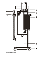
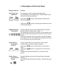
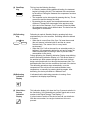
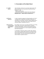
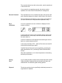
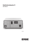
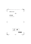
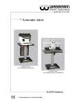
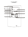
Cryo 5 Users Manual Front Panel Cryo 5 Back Panel Description of the Front Side 2a Therapy Time Adjustment 2b Digital Therapy Time Display 3a Air Current Flow Regulation Key 3b Air Current Flow Indication Display 4 Start/Stop Key 5a Defrosting Key 5b Defrosting Indication Display 6 After-Sales-Service Indication Display 7 Indication Display for Emptying the Defrosted Water Container 8 Indication Display for Cleaning the Filter 9 On/Off Indication Display 10 Stand-by Indication Display Description of the Back Side 1 On/Off Switch 11 Filter for Room Air 12 Access Door to the Container for Defrosted Water 13 Power Fuses 14 Identification Plate 15 Power Cable 16 Holder for Treatment Tube 17 Treatment Tube 18 Base and Castors Cryo 5 Table of Contents Page 1. Assembly Notice 5 2. Short Start-Up Procedure 6 3. Device Description 7 4. Description of the Front Panel 9 5. Description of the Back Panel 12 6. Modifications of the Treatment Parameters 13 7. Indications / Contraindications 14 8. Advice 15 9. Technical Information 16 10. Accessories 17 11. Safety and Maintenance • Safety • Functional and Safety Test • General Comment • Error Indications • Casing Care • Disposal 18 12. UL Classification 20 1. Assembly Notice 1. Castors (18) If the desired castors are not mounted on the Cryo 5, proceed as follows: • Lay the Cryo 5 on its left side, opposite to the one with the holder for the treatment tube. Pay attention not to damage the filter at the backside. • Castor axle can be plugged in the 4 special holes on the base of the unit. 2. Holder for Treatment tube (16) Holder is affixed with the 2 corresponding screws on the right side of the unit. 3. Treatment Tube (17) The tube can be screwed on below the front panel of the Cryo 5. The cold air exit is situated there. 4. Handpiece To be inserted into the distal end of the treatment hose to provide a smaller, more easily directed flow of air. 2. Short Start-Up Procedure 1. Switch on the Device Press the On/Off Key (1) The On/Off Indication Display (9) is then lit. When the Cryo 5 has been switched on, it begins to store a reserve of cold air. The unit needs 10 minutes to reach the minimal cold temperature. The loading time is indicated by the blinking of the Stand-By Indication Display (10), during which time the device cannot be used. 2. Utilization When the unit has reached its minimal cold temperature, it is ready for use and the Stand-By Indication Display (10) stops blinking. It is then constantly lit. 3. Beginning of the Treatment The unit is preset with an air current flow level of 3 (3b) and a treatment time of 15 minutes (2b). Select the desired air output. Press the Start/Stop Key. 4. End of the Treatment The end of the treatment is indicated by the stop of the air current flow and an acoustic signal. 3. Device Description What is the Cryo 5? A compact device which generates cold air for skin cooling. What does it produce? The Cryo 5 produces cold air at that can be applied with variable air current flows. What are the advantages of the Cryo 5? The preset parameters are user friendly. A large cold air production capacity is provided. Only ambient room air and electricity are required. No consumables. How can you reach the desired cold concentration? Depending upon the surface and the access of the area to be treated, the device offers 6 air current flow levels (level 1 = 300 l/min, level 6 = 700 l/min.). The Running of the Cryo 5 In order to employ Cryo 5 in its entire capacity, the daily running stages and principal elements should be understood. The Cryo 5 is basically composed of the following elements: - a "cold circuit" with a cold reserve, - a compressor, - a cooling fan (Fan C), situated in the low part of the unit, - a therapy fan (Fan T), - a defrosting system of the cold reserve, - a micro-processor controlled driving system. The daily running of the Cryo 5 consists of the following stages: The Minimal Load With "Load", we mean the time the device needs to produce a certain quantity of cold that it will store in its reserve. The "Minimal Load" of the Cryo 5 begins to be created as soon as the device is switched on. This phase is characterized by the simultaneous working of the compressor and the Fan C. These 2 elements are always functioning together. During the Minimal Load, no functions are available and the indication displays only bring a horizontal slash; no therapy is possible. When the unit has reached its minimal cold temperature, the Stand-By Indication Display (10) stops blinking. The compressor and Fan C still function and now produce the Additional or Total Load. The Total Load (Additional) The Total Load refers to the steady maintenance of the maximum cold temperature in the cold reserve. For example: During a treatment (Starting of Fan T with the Start Key), the compressor and the Fan C run automatically in order to compensate for the loss of cold capacity. When the Fan T stops (end of treatment) the compressor and Fan C will continue running in order to complete the cold reserve. During this loading period, treatment is possible. Afterwards, the unit remains in Stand-By Mode. The Stand-by If the device is not used for approximately 30 minutes, (in Standby Mode), the cold reserve will naturally lose part of its capacity. The compressor and Fan C will then start running in order to complete the cold reserve. During the Stand-by Mode, treatment is possible. Cold reserve additions are made automatically. The frequency required to maintain adequate cold reserve may change according to the climatic conditions around the Cryo 5. Important Advice for Optimal Use The first treatment should be made after the cold reserve is complete or Total Load and not after the Minimal Load. Otherwise, the possibility exists that the unit may not have enough cold reserve for subsequent treatments; it would then automatically proceed to the Minimal Load and treatment would not be possible for a few minutes. 4. Description of the Front Panel Displays and Keys Function (2a) Therapy Time Adjustment The therapy time can be adjusted with these 2 keys. Any modification of the treatment time in Stand-By Mode will be stored for the following treatments. Lightly typing , results in decreasing the treatment time from 15 to 0 minutes. Lightly typing , results in increasing the treatment time from 15 to 30 to 60 minutes. (2b)Digital Therapy Time Display During the Minimal Load or the Defrosting Phase, this display does not indicate a treatment time, rather "--:--". The therapy time is pre-set at 15 minutes, but is modifiable to suit the user’s needs. During treatment, the time counts down by the second. At the end of treatment, 00:00 is indicated in the Digital Therapy Time Display. The end of the treatment is indicated by the stop of the air current flow and an acoustic signal. (3a) Air Current Flow Regulation Key The unit is preset with an air current flow 3. But it may be modified before, as well as during the treatment. Lightly typing results in reducing the air current flow to Level 1. Lightly typing results in increasing the air current flow to Level 6. Holding the key pressed modifies the air current flow each second. (3b) Air Current Flow Indication Display During the Minimal Load or the Defrosting Phase, this display indicates "-". When the Minimal Load has been reached, it indicates the preset Level 3. (4) Start/Stop Key This key has the following functions: • In Stand-by mode or during additional loading, the treatment begins by pressing this key. The treatment time counts down by the second. During the treatment the compressor functions permanently. • The treatment can be interrupted by pressing this key. The air current flow and the therapy time stop. • By pressing this key again, the interrupted treatment can be continued. Therapy time starts again at the previous value. • At the end of the treatment, Cryo 5 returns to Stand-by Mode. All parameters return to their default value. The device can be used again for a treatment. (5a) Defrosting Key Defrosting is made in Stand-by Mode by pressing both keys simultaneously for a few seconds. Defrosting should be started in 2 cases: • When the air current flow of the Cryo 5 is lower than normal (the cold reserve is blocked with ice and the air cannot circulate freely. The cause of this is a very humid environment). • When the Cryo 5 will not be used for an extended period (i.e. holidays), it is suggested to defrost the unit and to empty the Water Container prior to leaving in order to prevent water accumulation in the device. During defrosting, the Stand-By Indication Display stops blinking and the Defrosting Indication Display is lit. The device draws in the ambient air, which passes through the cold circuit (without being cooled) and draws it out through the treatment tube. The defrosted water flows into the container at the back of the device. The defrosting procedure stops automatically, once the temperature of the cold circuit has reached ambient room temperature, or manually by pressing both keys again. After defrosting, the device proceeds to a Minimal Load. (5b)Defrosting Indication Display It indicates that the defrosting procedure is running. Once completed, the display stops blinking. (6) After-SalesService Indication Display This indication display is lit when the Cryo 5 presents a defect in the functioning. It is indicated by an acoustic signal and an error number in the Digital Therapy Time Display: F --. It is then better to switch off the device and call your distributor. With the error number, he can give instructions on how to proceed. (7) Indication Display for Emptying the Defrosted Water Container This display indicates that the container for defrosted water should be emptied. The container is accessible through the door at the back of the device. When the indication display is lit, no treatment is possible. (8) Indication Display for Cleaning the Filter In order to protect the cold circuit and to control the purity of the air drawn out of the Cryo 5, a filter has been installed (11) at the back of the device. The indication display is lit when the filter should be cleaned. Switch off the device and clean the filter with a vacuum. After cleaning, the filter display must be switched off manually. Proceed as follows: Hold the Start/Stop key pressed and switch on the device. (9) On/Off Indication Display This display is lit as long as the device is switched on. If it should go out along with the other indication displays, it is possible that a malfunction of the Cryo 5 has occurred which burned out the primary fuses of the device. In this case, please contact your After-Sales-Service Representative, who will then check the cause of the break down and change the primary fuses if needed. (10) Stand-By Indication Display • When this display is lit, the Cryo 5 is ready for use; it has enough cold capacity to proceed to treatments. • When this display blinks, the Cryo 5 is proceeding to a Minimal Load or defrosting. No treatment is then possible. 5. Description of the Back Panel (1) On/Off Switch Upon switching on the Cryo 5, an acoustic signal sounds. The device checks the correct functioning of keys and indication displays in 2 ways: - Graphic elements check - Typical display check with treatment time and parameters. Afterwards, Cryo 5 begins to store its cold reserve and all displays indicate "--" until the device is ready for use. (11) Filter for Room Air In order to clean the treatment air of larger impurities, the Cryo 5 is equipped with a metallic filter at the back of the device. Its maintenance is very simple: it should be cleaned regularly with a vacuum cleaner. The operation must only be made when the indication display for cleaning the filter is lit. (12) Access Door to the Container for Defrosted Water By switching on the Cryo 5 or by starting "defrosting", the cooling system warms and produces defrosted water. The Water Container holding approx. 2 liters can be reached through the door at the rear of the device. It can be opened by pushing the black slide downwards. It is advisable to disinfect the Water Container after emptying. The level sensor (hanging ball) should also be cleaned. Check before closing the door to be sure that the ball is placed in the Water Container. The device should only be used when the Water Container is placed in the unit. 6. Modification of Preset Parameters Cryo 5 provides the possibility to individualize the treatment according to your needs. Air Current Flow Air Current Flow is preset at Level 3 and can be modified by pressing the keys /. Treatment Time Treatment Time is preset at 15 minutes; it may be modified to 30:00 and 60:00 minutes. When these parameters are modified in Stand-by Mode (before pressing Start/Stop to begin a treatment) they are stored until the device is switched off. After switching off and on, the preset parameters are available again. 7. Indications / Contra-Indications Indications The Cryo 5 Cold Air Device is intended to minimize discomfort associated with laser treatments. Alternative uses include skin cooling as a local anesthetic for procedures that induce minor discomfort.. Contra-Indications • • • • • Hyper-sensitivity to cold Areas of impaired sensation Areas of impaired circulation Open wounds Do not use in the presence of explosive gases. 8. Advice Caution • After transporting Cryo 5 (especially sideways), wait at least 30 minutes before switching on the unit. • Do not place the Cryo 5 near a heating device: heating system, fango unit, sauna, etc... Insure a minimum of 24” free space behind Cryo 5 for air circulation. • Under extreme environmental conditions (over 86°F and high humidity) Cryo 5´s cooling capacity may be reduced. • Electrical and magnetic fields may interfere with the normal functioning of the device. The use of Cryo 5 close to any device generating electromagnetic fields (radiology, diathermy...) is impermissible. • Cryo 5 packaging is to be disposed of and kept out of the reach of children. • Cryo 5 should not be used the presence of explosive or flammable gases. 9. Technical Information Operating Voltage : 120V / 60 Hz Thermal-Magnetic Circuit Breaker : 12A or 14A Power Input : 1.4 kVA Power Input in Stand-by : about 260 W Volume Level : 70 dBa max. Treatment Temperature : -29°F max. (-35°C) Air Volume : 1000l/min max. Protection Class : Class I, Type B according IEC 601-1 MDD/MPG : Class Ila Treatment Tube Length : 71 inches (180 cm) Housing Dimensions : H 38 inches (970 mm) / W 13 inches (330 mm) / L 18 inches (460 mm) : W 470 mm / L 510 mm Dimensions of the Base Height with Castors 3 Inches (75 mm) : 43 inches (1080 mm) Weight : 121 lbs. (55 kg) Environmental Conditions : Temperature from +50°F to +95°F : Steady humidity level from 30 to 95% : Pressure from 700 hPa to 1060 hPa Storage Conditions : Temperature from -38°F to +158°F : Relative humidity from 10 to 100% : Pressure from 500 hPa to 1060 hPa Packaging : The device should only be shipped in the original packaging Storage and shipment only with an empty water container! Explanation of Labels Technical changes possible Device Type B: Protection level against electric shock. Refer to user manual! 10. Accessories Only authorized accessories should be used. Accessories delivered with unit 1 User Manual 1 air hose 1 mounting bracket for air hose 1 Container for defrosted water Available Accessories* Accessory Number 95370000 80025520 65440611 80400751 65370620 95372210 * Changes possible Air Hose Container for defrosted Water Base Castor Ø 75 mm mounting bracket for air hose Air Hose 11. Safety and Maintenance Safety Cryo 5 is produced in accordance with Safety Standard VDE 0750 Part 1 (IEC 601-1), UL 2601, Good Manufacturing Practices, and Safe Medical Devices Act and Amendments. As the manufacturer, Zimmer Elektromedizin GmbH can only be held responsible for safety and reliability of the device when: • the device is connected to the correct “hospital grade” electrical outlet, • the device is used in accordance with the User Manual, • repairs, modifications or any other changes are made only by those authorized to do so by Zimmer Elektromedizin. The device consists of no parts which must be user-supplied. (The user must only vacuum the filter (11) when the indication light is lit, and empty the Water Container (12) when full.) Functional and Safety Test If any functional and safety test is required, proceed as follows: These control checks should only be made by knowledgeable, qualified personnel with the practical necessities, which enable these technical checks to be independently performed. The following controls must be made: • Control of the outside function and safety state of the device and accessories. • Control of readability of descriptions and displays. • Control of functioning according User Manual, Chapter 4, On/Off Switch. • Control of the protective earth resistance according IEC 601-1 maximal value: 0,2 Ω. • Control of ground leakage current according UL 2601 maximal value: 300 µA. The controls checked, as well as the results, must be mentioned in the device book. If any control is not operating correctly, the device must be repaired or the user must be informed that it is dangerous. General Comment This User Manual is to be considered as part of the device itself and is therefore always to be kept in close vicinity of the device. The User Manual is the basis for correct usage and handling of the device as well as for the patients and operators safety. Error Indications If an error is detected, an error indication is displayed on the screen as follows: In some cases, the error is self-correctable after the device has been switched-off. In this case, wait a few seconds and switch the device back on. If the error indication is still displayed after switching the device back on, contact customer service. In the event of an Error “F22”, switch off the device and wait 30 minutes before switching on again. Certified Service Personnel can be reached by contacting the sales representative or by contacting Zimmer Elektromedizin directly. When the expulsed air or air volume temperature is decreasing, defrosting is necessary. Casing Care Cryo 5 casing should be cleaned with commercial plastic cleaner. Glass front panel, treatment tube and nozzels are easy to be cleaned with a non abrasive glass cleaning product. Disposal The device must be given to specifically authorized personnel or organization for disposal. 12. UL Classification The device bears the following UL Mark: CLASSIFIED BY UNDERWRITERS LABORATORIES INC. WITH RESPECT TO ELECTRIC SHOCK, FIRE, MECHANICAL HAZARDS ONLY IN ACCORDANCE WITH UL 2601-1 AND CAN/CSA C22.2 NO. 601.1 1KD1