1
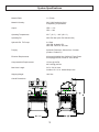
MH
USER MANUAL
Dispensing System
5845 WEST 82ND STREET
INDIANAPOLIS, INDIANA
46278 U.S.A.
Phone (317) 875-5592
Fax
(317) 875-5456
Email [email protected]
Web www.glascraft.com
Table Of Contents
Introduction
About This Manual.................................................................................................................................................... 1
Parts & Illustrations
MH System List / Options / Repair Parts Kits ..........................................................................................................
System Specifications ..............................................................................................................................................
22100-XX MH System Console ...............................................................................................................................
22100-XX MH System Assembly .............................................................................................................................
22140-XX MH Control Box Assembly ......................................................................................................................
22100-XX MH Schematic .........................................................................................................................................
22120-00 Fluid Section Assembly ...........................................................................................................................
22105-00 Iso Heat Exchanger Assembly ................................................................................................................
22110-00 Poly Heat Exchanger Assembly ..............................................................................................................
22023-01 Manual Hose Assembly ..........................................................................................................................
Typical System Layout Diagram ..............................................................................................................................
Typical System Hose Connections For 50 Ft. ..........................................................................................................
Typical System Connections For 100-300 Ft. ..........................................................................................................
2
3
4
6
18
25
28
30
35
40
41
42
43
Safety
Urethane Safe Handling and Use of Foam Equipment ............................................................................................ 44
Installation
Instructions ...............................................................................................................................................................
Optional Transfer Pump Installation / Air Dryer Kit ..................................................................................................
Electrical Connections ..............................................................................................................................................
Hydraulic Pack .........................................................................................................................................................
Operation
Initial Start-up Procedures ........................................................................................................................................
Over Pressure System Protection ............................................................................................................................
Over Pressure Problem Correction ..........................................................................................................................
System Shut Down ...................................................................................................................................................
System Daily Start-Up ...............................................................................................................................................
48
50
51
51
52
55
56
57
58
Limited Warranty Policy ................................................................................................................................ 60
Notes ..................................................................................................................................................................... 61
If You Have An Equipment Problem ......................................................................................................... 64
For Your Reference .................................................................................................... INSIDE BACK COVER
Introduction
About This Manual
The information in this document is intended only to
indicate the components and their normal working
relationship typical use. Each assembly should be
directed by a GlasCraft distributor or
made from the GlasCraft assembly instructions provided.
Before operating, maintaining or servicing any
GlasCraft system, read and understand all of the
technical and safety literature provided with GlasCraft
products. If you do not have the proper or related
manuals and safety literature for your GlasCraft system, contact your GlasCraft distributor or GlasCraft,
Inc.
This manual provides information for the assembly,
operation, maintenance and service of this GlasCraft
product as used in a typical configuration. While it
lists standard specifications and procedures, some
deviations may be found.
In this GlasCraft technical and safety publication, the
following advisories will be provided where
appropriate:
NOTE
In order to provide our users with the most up-to-date
technology possible, we are constantly seeking to improve products. If technological change occurs after
a product is on the market, we will implement that
technology in future production and, if practical, make
it available to current users as a retrofit, up-date or
supplement. If you find some discrepancy between
your unit and the available documentation, contact
your GlasCraft distributor to resolve the difference.
GlasCraft, Inc. reserves the right to change or modify
this product as it deems necessary.
Is information about the procedure in progress.
CAUTION
Is imperative information about equipment
protection.
WARNING
Is imperative information about personal safety.
Careful study and continued use of this manual will
provide a better understanding of the equipment and
process, resulting in more efficient operation, longer
trouble-free service and faster, easier troubleshooting.
1
Parts & Illustrations
MH Dispensing System
45lbs.(21kg.)/min. Spray or Pour Dispensing System
Includes
22100-XX
22023-01
18006-01
17254-XX
17661-XX
59934-04
17798-25
18101-01
1017-00
GC-1239
MH Dispencing System
High Pressure Heated Hose Assembly
Whip Hose Assembly
Probler Gun Assembly • W/ Round Spray Mixing Chamber
Gun Service Kit
Dioctyl Phthalate, 1 Qt.
Air Hose Assembly
1/4” X 1/4” Fitting
1/4” X 1/4” Hose Adapter
System User Manual
Options
22023-01
22094-00
High Pressure Hose Assy., 50 Ft.
Required To Complete Hose Electrical Circuit
100 Ft. Minimum Hose Length
1 22023-01 High Pressure Hose
Recommended Service Kits
17661-XX
21063-00
21277-00
22190-00
Gun Service Kit
Heat Exchanger Kit
Pump Fluid Section Repair Kit
Hydraulic Fluid Pump
2
System Specifications
Material Ratio:
1:1 (Fixed)
Material Viscosity:
200- 2000 Centipoise (Cps)
At Operating Temperatures
Output:
GPS = .021
GPC = .042
Operating Temperatures:
32º F ( 0º C ) - 190º (88 º C )
Operating Psi:
3000 Psi. Max (Over Psi Switches Set)
Hydraulic Psi To Pumps:
2:1 Ratio
1000 PSI. Hydraulic PSI.
2000 PSI. Fluid PSI. Per Side.
Purging:
Automatic Pneumatic, Solvent-free, Constant
(Probler / Probler P2)
Electrical Requirements:
63 Amps @ 208/240 Vac, 50/60 Hz Three Phase
63 Amps @ 380 Vac, 50/60 Hz Three Phase
Compressed Air Requirements:
15 Cfm @ 100 Psi
425 Liters @ 6.8 Bar
Max Hose Length:
310’ X 3/8 I.d. Hose
Includes 10’ X ¼ I.d. Heated Whip Hose
Shipping Weight:
1000 Lbs
Overall Dimensions:
3
22100-XX MH System Console
4
22100-XX MH System Console
1
MAIN POWER SWITCH
Controls power and door; handle must point 1 to
energize power, handle must point to 0 to open control
box door. White pilot indicates when lighted, that the
main power is on.
2
EMERGENCY STOP PUSH
BUTTON
To stop all functions, push down on red button. To reset,
turn handle on push button. All functions will remain off
until main power switch is turned off and back on.
3
AMMETER
An instrument for measuring amperes to the primary
side of the hose’s transformer.
4
HOSE TEMPERATURE
CONTROLLER
Controls temperature of liquid inside the heated hoses.
To set desired temperature, press the up or down button
until you reach desired temperature From this point, the
temperature control is completely automatic.
5
6
7
WHITE PILOT LIGHT
POLY PRESSURE GAUGE
HYDRAULIC PRESSURE GAUGE
8
HYDRAULIC PRESSURE KNOB
9
HYDRAULIC OIL FILL PORT
Remove cap to fill tank with recommended hydraulic oil.
10
POLY DUMP VALVE
Removes pressure and material from POLY side.
11
ISO DUMP VALVE
Removes pressure and material from ISO side.
12
ISO PRESSURE GAUGE
Indicates material pressure.
13
HOSE THERMOCOUPLE OUTLET
14
ON PUSH BUTTON
Power outlet for hose thermocouple.
Powers the controller. It requires 10 seconds for the
Controller to respond.
15
ISO TEMPERATURE
CONTROLLER
Controls temperature of liquid inside ISO heater. To set
desired temperature, press the up or down button until
you reach desired temperature. From this point, the
temperature control is completely automatic.
16
POLY TEMPERATURE
CONTROLLER
Controls temperature of liquid inside the poly heater.
To set desired temperature, Press the up or down
button until you reach desired temperature. From this
point, the temperature control is completely automatic.
17
OVER-PRESSURE RESET
BUTTONS
When over-pressure is detected, the hydraulic power
pack will be shut down, and will remain off until
pressure is reduced and the push button is reset.
18
ON PUSH BUTTON
Powers the hydraulic power pack.
19
OFF PUSH BUTTON
Removes power to the hydraulic power pack.
20
COUNTER
Counts pumps cycles. (.079x pump cycles = us gallons)
(.238x pump cycles= liters)
Indicates power on.
Indicates material pressure.
Indicates hydraulic pump pressure
Increases or decreases hydraulic pressure. Turn
clockwise to increase pressure. Turn counter-clockwise
to decrease pressure.
5
22100-XX MH System Assembly
REVISION R
6
22100-XX MH System Assembly
Detail
F
REVISION R
7
22100-XX MH System Assembly
Detail
G
REVISION R
8
22100-XX MH System Assembly
REVISION R
9
22100-XX MH System Assembly
REVISION R
10
22100-XX MH System Assembly
REVISION R
11
22100-XX MH System Assembly
REVISION R
12
22100-XX MH System Assembly
REVISION R
13
22100-XX MH System Assembly
REVISION R
14
22100-XX MH System Assembly
REVISION R
15
22100-XX MH System Assembly Parts List
PART
NUMBER
DESCRIPTION
PART
NUMBER
DESCRIPTION
10009-07
ELBOW FITTING
22113-01
HEAVY SPLIT LOCK WASHER
1625-23
PLUG
22114-01
NUT
17597-01
CONNECTOR FITTING
22115-00
UPPER SHAFT CAM ADAPTER
18428-01
NEEDLE VALVE
22118-00
ISOLATION HOSE MOUNTING BLOCK
18468-03
FITTING
22120-00
1.5:1 FLUID SECTION
19616-00
SWIVEL CASTER
22121-00
STAND-OFF
20053-24C
SCREW
22122-00
PUMP STAND-OFF
20188-20C
SCREW
22123-00
CHANGEOVER STAND-OFF
20188-28C
SCREW
22124-00
BOTTOM PUMP BRACKET
20639-03
GAUGE
22125-00
MOUNTING PLATE
20655-02
ELBOW FITTING
22126-00
SIDE FRAME SUPPORT
20732-03
TUBING
22127-00
VERTICAL FRAME SUPPORT
20735-01
ELBOW FITTING
22128-00
FRONT FRAME SUPPORT
20735-04
ELBOW FITTING
22129-00
BOTTOM MOUNTING BRACKET
20735-04
ELBOW FITTING
22130-00
FLUID SECTION GUARD
20750-03
SWIVEL TEE FITTING
22131-00
MOUNTING PLATE
20796-02
FITTING
22132-00
BOTTOM CHANGEOVER PLATE
20796-01
FITTING
22133-00
TOP CHANGEOVER PLATE
20849-01
UNION BULKHEAD FITTING
22134-00
HYDRAULIC FLUID PUMP TOP PLATE
21071-02
FIBER WASHER
22135-00
TRANSFORMER MOUNTING PLATE
21081-02
CONDUIT CONNECTOR
22136-00
STROKE COUNTER BRACKET
21119-00
TRANSFORMER
22137-00
YOKE
21192-01
TEE HANDLE BODY VALVE
22138-00
TRANSFORMER COVER
21283-00
ROLLER SWITCH
22139-00
LIMIT SWITCH MOUNTING BRACKET
21284-40C
SCREW
22140-XX
CONTROL BOX ASSEMBLY
21286-01
LOCK WASHER
22145-01
HYDRAULIC MOTOR
21287-01
NUT
22148-00
DECAL HOSE SECTION
21329-05
MATERIAL HOSE ASSEMBLY
22151-00
HYDRAULIC FLUID PUMP
21390-00
AIR MOTOR STAND-OFF
22155-00
DECAL HYDRAULIC PRESSURE
21402-00
3-WAY LOCKOUT VALVE
22156-01
TEE FITTING
21433-02
ELBOW FITTING
22160-01
CAP
21660-00
2-WAY CONTROL VALVE
22161-00
ROTATION DECAL
21819-00
LIVE WIRE DECAL
22164-00
DIRECTIONAL CONTROL VALVE
21830-00
HIGH PRESSURE SWITCH
22165-00
SPOOL VALVE MANIFOLD
21847-00
CE PLATE
22167-00
FRONT HYDRAULIC MOTOR COVER
21881-00
PRESSURE GAUGE
22168-00
BACK HYDRAULIC MOTOR COVER
22083-00
RUN DECAL
22169-00
SIDE HYDRAULIC MOTOR COVER
22084-00
RETRACT DECAL
22172-00
COUNTER CHANGEOVER GUARD
22088-03
ISO ELECTRIC PLUG ASSEMBLY
22173-00
HYDRAULIC PUMP SUPPORT BRACKET
22088-06
POLY ELECTRIC PLUG ASSEMBLY
22177-01
MATERIAL HOSE ASSEMBLY
22105-00
(ISO) HEAT EXCHANGER ASSEMBLY
22212-02
BULKHEAD FITTING
22110-00
(POLY) HEAT EXCHANGER ASSEMBLY
22506-00
2 IN / 2 OUT TERMINAL
22543-00
SWIVEL FITTING
16
22100-XX MH System Assembly Parts List
DESCRIPTION
PART
NUMBER
DESCRIPTION
22706-16
SCREW
8155-48C
SCREW
23303-00
TOP TRANSFORMER COVER PANEL
8155-80C
SCREW
BOTTOM TRANSFORMER COVER
8156-32C
SCREW
PART
NUMBER
23304-00
23306-00
DIN RAIL TERMINAL
8301-24
SCREW
23307-00
TERMINAL END CLAMP
8301-40C
SCREW
23308-00
END BARRIER
8560-03
CONNECTOR FITTING
4342-04
ELBOW FITTING
8560-05
FITTING
4342-23
TEE PIPE FITTING
8560-07
FITTING
5307-01
CONDUIT NUT
8560-11
CONNECTOR FITTING
6782-03
TEE FITTING
8560-17
CONNECTOR FITTING
6782-23
TEE FITTING
9704-03
TUBING
7315-11
RUBBER GROMMET
9869-13
SCREW
7486-03
FLAT WASHER
9869-20
SCREW
7486-04
FLAT WASHER
9943-24F
SCREW
7486-05
FLAT WASHER
9944-32C
SCREW
7486-05
FLAT WASHER
9944-40C
SCREW
7486-07
FLAT WASHER
9945-32C
SCREW
7486-10
LOCK WASHER
9955-40C
SCREW
7486-13
FLAT WASHER
9955-56C
SCREW
7486-13
FLAT WASHER
9955-64C
SCREW
7486-14
FLAT WASHER
9955-64C
SCREW
7486-27
FLAT WASHER
9955-72C
SCREW
7729-04
NUT
RM-856-04
ELBOW FITTING
7733-12
NUT
RS-118
ISO DECAL
7733-14
NUT
RS-119
POLY DECAL
7733-17
NUT
RS-126
DECAL HOSE CURRENT
7733-34
NUT
RS-141-02
CORD GRIP
7733-42
NUT
7734-03
LOCK WASHER
7734-05
LOCK WASHER
7734-06
LOCK WASHER
7734-07
LOCK WASHER
7734-10
LOCK WASHER
7734-12
LOCK WASHER
7957-40C
SCREW
7958-32C
SCREW
7966-10
PIPE FITTING
7966-15
FITTING
7966-17
PIPE FITTING
8115-03
FITTING
17
22140-XX MH Control Box Assembly
18
REVISION W
22140-XX MH Control Box Assembly
19
REVISION W
22140-XX MH Control Box Assembly
20
REVISION W
22140-XX MH Control Box Assembly
21
REVISION W
22140-XX MH Control Box Assembly
22
REVISION W
22140-XX MH Control Box Assembly Parts List
PART
NUMBER
DESCRIPTION
PART
NUMBER
DESCRIPTION
14626-01
FITTING
22119-00
63 AMP FUSE BLOCK
14638-02
BLIND RIVOT
22141-00
MH CONTROL BOX
1625-23
PIPE PLUG
22142-00
CONTROL BOX TRANSFORMER
17702-00
PILOT LAMP
22143-00
63 AMP FUSE
20226-00
SET SCREW
22146-01
63A SOLID STATE RELAY
20655-02
ELBOW FITTING
22146-02
50 AMP RELAY
21081-02
SWIVELLOK CONNECTOR
22150-02
(OPAQUE) PILOT LIGHT
21112-00
LCD COUNTER
22153-00
(MH) DECAL
21164-00
1/2 AMP FUSE
22154-00
(HYDRAULIC POWER) DECAL
21164-02
2 AMP FUSE
22162-00
CONDUIT CONNECTOR
21324-00
CONDUIT CONNECTOR
22163-00
30A AMMETER
21333-00
THERMOCOUPLE WIRE
22165-00
MH SPOOL VALVE MANIFOLD
21334-00
THERMOCOUPLE WIRE
22178-00
ON/OFF POWER SWITCH
21335-00
CIRCULAR PANEL JACK
22201-01
25A MECHANICAL CONTACTOR
21356-02
2 AMP MICROPROCESSOR
22422-01
10 AMP 3 POLE RELAY
21361-00
MINIATURE LAMP
22423-01
10 AMP 3 POLE RELAY SOCKET
21402-00
3-WAY LOCKOUT VALVE
22502-00
CIRCULAR PANEL JACK
21722-00
CONTROL BLOCK MOUNTING BRACKET
22506-00
2 IN / 2 OUT TERMINAL
21823-00
DIN RAIL
22507-00
TERMINAL END COVER
21824-16C
SCREW
22527-00
WIRING DUCT COVER
21848-00
CE DECAL
22528-00
WIRING DUCT
21854-00
PUSH BUTTON
22528-01
WIRING DUCT
21862-00
PUSH BUTTON
22709-02
4-POLE MECHANICAL CONTACTOR
21863-00
PUSH BUTTON
22753-00
(OVERPRESSURE/OVERTEMP) DECAL
21864-00
EMERGENCY STOP BUTTON
22849-01
20-25 MOTOR CIRCUIT CONTROLLER
21865-01
N.O. CONTACT BLOCK
4342-04
ELBOW FITTING
21865-02
N.C. CONTACT BLOCK
5307-01
CONDUIT NUT
21866-00
COUPLING PLATE
6782-03
TEE FITTING
21867-02
INSCRIPTION CAP
7486-05
FLAT WASHER
21867-03
INSCRIPTION CAP
7486-11
FLAT WASHER
21867-04
INSCRIPTION CAP
7486-27
FLAT WASHER
21867-05
INSCRIPTION CAP
7486-28
FLAT WASHER
21886-00
FRONT MOUNTING LAMP BLOCK
7733-06
NUT
21887-01
YELLOW COLOR CAP
7733-12
NUT
21887-02
OPAQUE COLOR CAP
7734-03
LOCK WASHER
21887-03
GREEN COLOR CAP
7734-06
LOCK WASHER
21888-03
CIRCUIT BREAKER
7735-16C
SCREW
21888-06
CIRCUIT BREAKER
7735-40C
SCREW
21888-06
CIRCUIT BREAKER
7959-72C
SCREW
21888-12
CIRCUIT BREAKER
8115-03
FITTING
21889-00
DIN RAIL FUSE HOLDER
8160-12F
SET SCREW
21892-01
DIN RAIL FINDER RELAY
9897-24C
SCREW
21893-01
DIN RAIL SOCKET RELAY
22104-00
LABEL
23
22140-XX MH Control Box Assembly Parts List
PART
NUMBER
DESCRIPTION
RS-118
(ISO) DECAL
RS-119
(POLY) DECAL
RS-121
(HOSE) DECAL
RS-122
(PRIMARY) DECAL
RS-124
(MAIN) DECAL
RS-126
(HOSE CURRENT) DECAL
RS-127
(HOSE CONTROL) DECAL
RS-141-02
CORD GRIP
24
22140-XX MH System Generic Ladder Schematic
25
REVISION W
22140-02 MH System 220 Volt 3 Phase Schematic
26
REVISION W
22140-03 MH System 380 Volt 3 Phase Schematic
27
REVISION W
22120-00 Fluid Section Assembly
REPAIR KIT: 21277-00
28
REVISION C
22120-00 Fluid Section Assembly Parts List
PART
NUMBER
DESCRIPTION
QTY.
1005-26
SNAP RING
1
13867-30
O-RING
1
13867-56
O-RING
3
19633-00
SPRING
1
20448-00
TIE ROD
4
20484-48C
SCREW
4
21255-01
SUPPORT SEAL
1
21256-00
PUMP HEAD
1
21257-00
PUMP CYLINDER
1
21258-00
PUMP SHAFT
1
21260-00
SPRING
1
21261-00
BALL
1
21263-00
PISTON GUIDE
1
21264-00
TRANSFER HOUSING SEAT
1
21265-00
FOOT VALVE HOUSING
1
21267-00
FOOT VALVE SEAT
1
21268-00
PUMP BASE
1
21269-00
BALL
1
21397-02
SHAFT EXTENSION
1
21433-02
ELBOW FITTING
1
21555-00
PUMP SEAL
1
21556-00
PUMP SEAL
1
21557-00
TRANSFER HOUSING
1
21731-00
SOLVENT CUP ADAPTER
1
21896-03
PACKING RETAINER
1
21897-03
FELT WIPER
4
7733-43
NUT
4
7734-08
LOCK WASHER
8
7959-24F
SCREW
1
8560-07
FITTING
1
29
REVISION C
22105-00 ISO Heat Exchanger Assembly
30
REVISION J
22105-00 ISO Heat Exchanger Assembly
31
REVISION J
22105-00 ISO Heat Exchanger Assembly
32
REVISION J
22105-00 ISO Heat Exchanger Assembly Parts List
PART
NUMBER
DESCRIPTION
QTY.
PART
NUMBER
DESCRIPTION
QTY.
11021-23
PLUG
1
21091-01
TURBULATOR SPRING
4
11021-24
PLUG
3
21092-00
HEATER TIE ROD
1
16254-05
FITTING
1
21093-01
THERMOCOUPLE FITTING
1
21038-00
FIBER WASHER
1
21094-01
ELBOW FITTING
1
21056-32C
SCREW
2
21096-00
THERMOSTAT MOUNTING PAD
4
21057-01
FIBER WASHER
2
21819-00
LIVE WIRE DECAL
1
21058-00
TUBE SENSOR ASSEMBLY
1
22108-00
OVERTEMP SWITCH
4
21059-00
HEATER TUBE ASSEMBLY
3
22705-20C
SCREW
4
21064-01
O-RING
1
4342-23
ELBOW FITTING
1
21064-02
O-RING
8
7486-03
FLAT WASHER
2
21065-16C
SCREW
4
7486-04
WASHER
2
21068-06C
SCREW
8
7486-05
WASHER
4
21071-01
FIBER WASHER
1
7733-42
NUT
2
21072-00
INSULATOR PAD
2
7734-04
LOCK WASHER
2
21074-00
THERMOCOUPLE
1
7734-06
LOCK WASHER
4
21076-00
(ISO) FRONT END PLATE
1
7734-10
LOCK WASHER
2
21077-00
DANGER DECAL
1
7958-20C
SCREW
4
21078-00
HEATER COVER
1
8612-08
BAND CLAMP
4
21079-00
(UNIVERSAL) REAR END PLATE
1
RS-118
ISO DECAL
2
21080-00
MOUNTING BRACKET
1
21081-02
SWIVELLOK CONNECTOR
1
21082-00
MOUNTING BRACKET
2
21083-01
FITTING
8
21089-00
HEATER ELEMENT
4
33
REVISION J
22105-00 ISO Heat Exchanger Schematic
Note
When replacing thermocouple p/n: 21074-00,
use kit p/n: 21214-01. Besure thermocouple
is touching heater element before tightening.
34
REVISION J
22110-00 POLY Heat Exchanger Assembly
35
REVISION J
22110-00 POLY Heat Exchanger Assembly
36
REVISION J
22110-00 POLY Heat Exchanger Assembly
37
REVISION J
22110-00 POLY Heat Exchanger Assembly Parts List
PART
NUMBER
DESCRIPTION
QTY.
PART
NUMBER
DESCRIPTION
QTY.
11021-23
PLUG
1
21086-00
(POLY) FRONT END PLATE
1
11021-24
PLUG
3
21088-00
(POLY) HEATER COVER
1
16254-05
FITTING
1
21089-00
HEATER ELEMENT
4
TURBULATOR SPRING
4
21038-00
FIBER WASHER
1
21091-01
21056-32C
SCREW
2
21092-00
HEATER TIE ROD
1
21057-01
FIBER WASHER
2
21093-01
THERMOCOUPLE FITTING
1
21058-00
TUBE SENSOR ASSEMBLY
1
21094-01
ELBOW FITTING
1
THERMOSTAT PAD
4
21059-00
HEATER TUBE ASSEMBLY
3
21096-00
21064-01
O-RING
1
21819-00
LIVER WIRE DECAL
1
21064-02
O-RING
8
22108-00
OVERTEMP SWITCH
4
21065-16C
SCREW
4
22705-20C
SCREW
4
ELBOW FITTING
1
21068-06C
SCREW
8
4342-23
21071-01
FIBER WASHER
1
7486-03
FLAT WASHER
2
21072-00
INSULATOR PAD
2
7486-04
WASHER
2
21074-00
THERMOCOUPLE
1
7486-05
WASHER
4
NUT
2
21077-00
DANGER DECAL
1
7733-42
21079-00
(UNIVERSAL) REAR END PLATE
1
7734-04
LOCK WASHER
2
21080-00
MOUNTING BRACKET
1
7734-06
LOCK WASHER
4
21081-02
SWIVELLOK CONNECTOR
1
7734-10
LOCK WASHER
2
SCREW
4
21082-00
MOUNTING BRACKET
2
7958-20C
21083-01
FITTING
8
8612-08
BAND CLAMP
4
RS-119
POLY DECAL
2
38
22110-00 POLY Heat Exchanger Assembly Schematic
Note
When replacing thermocouple p/n: 21074-00,
use kit p/n: 21214-01. Besure thermocouple
is touching heater element before tightening.
39
REVISION J
22023-01 MH Manual Hose Assembly
PART
NUMBER
DESCRIPTION
10262-04
NYLON HOSE
11745-10
HEAT SHRINK TUBING
13424-03
CABLE TIE
15998-02
TUBING
17896-01
UNION FITTING
18012-03
HEATED HOSE COVER
18101-01
ADAPTER FITTING
19490-01
SWIVEL HOSE FITTING
19506-01
COPPER STRIP
21341-01
MATERIAL HOSE
22021-01
(ISO) HOSE ASSY.
22022-01
(POLY) HOSE ASSY.
22088-01
MALE ELECTRIC PLUG
22088-02
ELECTRIC PLUG ASSY.
40
REVISION J
Typical System Layout Diagram
TOP VIEW
41
Typical System Hose Connection 50 Ft. Application
42
Typical System Hose Connection 100-300 Ft. Applications
43
Safety
Safe Handling And Use Of Urethane Foam
Equipment
Organic Peroxides and Dual Component Coatings. Local
codes and authorities also have standards to be followed
in the operation of your spraying equipment. Chemical
manufacturer’s recommendations should be obtained
and considered. Your insurance carrier will be helpful in
answering questions that arise in your development of
safe procedures.
Introduction
Any tool, if used improperly, can be dangerous. Safety
is ultimately the responsibility of those using the tool. In
like manner, safe operation of polyester processes is
the responsibility of those who use such processes and
those who operate the equipment. This manual outlines
procedures to be followed in conducting polyester operations safely.
Personnel Safety Equipment
GlasCraft recommends the following Personal Safety
Equipment for conducting safe operations of the Polyester Systems:
All personnel involved in dispensing operations should
read and understand this manual. It is most important
that equipment operators, maintenance, and supervisory personnel understand the requirements for safe
operation.
This manual cannot answer every circumstance; each
user should examine his own operation, develop his
own safety program and be assured that his equipment
operators follow correct procedures. GlasCraft hopes
that this manual is helpful to the user and recommends
that the precautions in this manual be included in any
such program.
GlasCraft recommends that the user consult the state
and local regulations established for all Safety equipment
listed.
Urethane foam systems are comprised of several different chemical compounds, some of which may be hazardous if improperly used.
1.
Handle chemicals safely.
2.
Provide adequate ventilation.
3.
Provide adequate safety equipment (gloves, respirators, safety glasses, protective clothing, etc.) for operators and all others working in areas where they may
be exposed to the chemicals or their vapors.
4.
Avoid operating equipment which has given any
indication of malfunction.
5.
Become fully acquainted with the equipment and
chemicals used.
Operating Safely
In operating urethane foam equipment safely, user should
make every effort to:
CAUTION
Particular caution must be taken with respect to the
vapors released during the use of urethane foam systems.
Isocyanate compounds are used in urethane foaming
operations. The medical history of persons who may be
exposed to such isocyanates should be examined. It is
recommended that individuals with a history of chronic
respiratory ailments should avoid exposure to all isocyanates.
Handling Chemicals Safely
Storage of polyisocyanates, diamines, and organic solvents should be isolated and restricted to specially constructed storage rooms. Store chemicals in original containers and according to manufacturer’s recommendations
listed on the container. Maximum ambient temperatures
to which such chemicals should be exposed are specified
by the manufacturer and MUST NOT be exceeded either
in the storage area or in the spraying or pouring area.
In addition to the manual, GlasCraft recommends that
the user consult the regulations established under the
Occupational Safety & Health Act (OSHA), particularly
the following sections:
•
•
•
1910.94 Pertaining to ventilation.
1910.106 Pertaining to flammable liquids.
1910.107 Pertaining to spray finishing opera
tions, particularly Paragraph (m)
44
Safety
To avoid moisture contamination, do not open containers until ready for use. After use, the remaining material
should be re-sealed in the original container and stored in
areas away from moisture.
During clean-up of spilled isocyanate component, respirators, gloves and eye protection must be worn. Isocyanates
which have been spilled can be controlled by covering
them with dry sawdust and/or other absorbent, inert materials. Care should be taken to avoid skin contact. The absorbent material and the absorbed isocyanate should be
collected promptly, placed in an open-top container, and
treated with dilute solutions of ammonium hydroxide and/
or alcohol. While being treated in this manner, the material
should be in an adequately ventilated area. Clothing on
which any material has been spilled should be removed
immediately, and cleaned before being worn again.
Clean-Up Solvents
WARNING
A hazardous situation may be present in your pressurized
fluid system!
Halogenated Hydrocarbon Solvents can cause an explosion when used with aluminum or galvanized components
in a closed (pressurized) fluid system (pumps, heaters, filters, valves, spray guns, tanks, etc.).
The explosion could cause serious injury, death and/or
substantial property damage.
Cleaning agents, coatings, paints, etc. may contain Halogenated Hydrocarbon Solvents.
Some GlasCraft spray equipment includes aluminum or
galvanized components and will be affected by
Halogenated Hydrocarbon Solvents.
There are three key elements to the Halogenated Hydrocarbon (HHC) solvent hazard.
1.
The presence of HHC solvents. 1,1,1-Trichloro
ethane and Methylene Chloride are the most common of
these solvents. However, other HHC solvents are suspect
if used; either as part of paint or adhesives formulation, or
for clean-up or flushing.
2.
Aluminum or Galvanized Parts. Most handling
equipment contains these elements. In contact with these
metals, HHC solvents could generate a corrosive reaction
of a catalytic nature.
45
3.
Equipment capable of withstanding pressure. When HHC solvents contact aluminum or galvanized parts inside a closed container, such as a pump,
spray gun, or fluid handling system, the chemical reaction can, over time, result in a build-up of heat and pressure, which can reach explosive proportions.
When all three elements are present, the result can be
an extremely violent explosion. The reaction can be
sustained with very little aluminum or galvanized metal:
any amount of aluminum is too much.
The reaction is unpredictable. Prior use of an HHC
solvent without incident (corrosion or explosion) does
NOT mean that such use is safe. These solvents can
be dangerous alone (as a clean-up or flushing agent) or
when used as a component of a coating material. There
is no known inhibitor that is effective under all circumstances. Furthermore, the mixing of HHC solvents with
other materials or solvents, such as MEK, alcohol, and
toluene, may render the inhibitors ineffective.
The use of reclaimed solvents is particularly hazardous.
Reclaimers may not add any inhibitors, or may add
incorrect amounts of inhibitors, or may add improper
types of inhibitors. Also, the possible presence of water
in reclaimed solvents could feed the reaction.
Anodized or other oxide coatings cannot be relied upon
to prevent the explosive reaction. Such coatings can be
worn, cracked, scratched, or too thin to prevent contact.
There is no known way to make oxide coatings or to
employ aluminum alloys, which will safely prevent the
chemical reaction under all circumstances.
Several solvent suppliers have recently begun promoting HHC solvents for use in coating systems. The
increasing use of HHC solvents is increasing the risk.
Because of their exemption from many State Implementation Plans as Volatile Organic Compounds (VOC’s),
their low flammability hazard, and their not being classified as toxic or carcinogenic substances, HHC solvents
are very desirable in many respects.
Safety
WARNING
If you are now using Halogenated Hydrocarbon solvents
in pressurized fluid systems having aluminum or galvanized wetted parts,
IMMEDIATELY TAKE THE FOLLOWING STEPS:
•
Empty system, shut-off, completely depressurize in accordance with equipment service instructions.
•
Remove equipment from service, disassemble
in accordance with equipment servicing instructions.
•
Inspect all parts for corrosion and/or wear. Replace any damaged parts.
•
Thoroughly clean all parts of the equipment with
a non-halogenated solvent and reassemble in accordance with equipment servicing instructions.
•
Flush equipment with non-halogenated solvent.
•
Do NOT reuse equipment with HHC solvents or
with materials containing such solvents.
•
Material suppliers and/or container labels should
be consulted to ensure that the solvents used are compatible with your equipment.
Adequate ventilation (as covered in OSHA Section
1910.94 and NFPA No. 91) is important wherever solvents are stored or used, to minimize, confine and exhaust the solvent vapors.
Solvents should be handled in accordance with OSHA
Section 1910.106 and 1910.107.
Toxicity of Chemicals
GlasCraft recommends that you consult OSHA Sections
1910.94, 1910.106, 1910.107 and NFPA No. 33, Chapter
14, and NFPA No. 91.
Contact your chemical supplier(s) and determine the toxicity of the various chemicals used, as well as the best
methods to prevent injury, irritation and danger to personnel.
Also determine the best methods of first aid treatment for
each chemical used in your plan
NOTE
First Aid
If chemicals containing isocyanate are splashed on the
skin, they can produce ill effects. Steps to counteract
such effects should be started immediately.
TAKE IMMEDIATE ACTION...
Halogenated Hydrocarbon solvents are dangerous
when used with aluminum components in a closed fluid
system.
Apply Tincture of Green Soap, full strength, to the contaminated area. If Tincture of Green Soap is not immediately available, wash the exposed area repeatedly with
soap and water. Soap and water is not as desirable as
using Tincture of Green Soap because many isocyanate
components are not easily dissolved in water. In addition,
soap and water does not form a barrier to the isocyanate.
GlasCraft is aware of NO stabilizers available to prevent
Halogenated Hydrocarbon solvents from reaction under
all conditions with aluminum components in a closed
fluid system.
Consult your material supplier to determine whether your
solvent or coating contains Halogenated Hydrocarbon
Solvents.
GlasCraft recommends that you contact your solvent
supplier regarding the best non-flammable clean-up solvent with the heat toxicity for your application.
If, however, you find it necessary to use flammable
solvents, they must be kept in approved, electrically
grounded containers.
Bulk solvent should be stored in a well-ventilated, separate building, 50 feet away from your main plant.
You should allow only enough solvent for one day’s use
in your laminating area.
“NO SMOKING” signs must be posted and observed in
all
areas of storage or where solvents and other
flammable materials are used.
46
After approximately two to four minutes, wash off the
Tincture of Green Soap with water. If there is still an indication of isocyanate present, repeat the application. If the
isocyanate contamination is on the facial area, care must
be taken to avoid getting the Tincture of Green Soap in
the eyes.
If the person develops breathing difficulties, oxygen
should be administered. Quite often the exposed person
will experience residual effects such as coughing spells.
CONTACT PHYSICIAN IMMEDIATELY.
WARNING
Contact a doctor immediately in the event of an injury
and give him the information you have collected. If your
information includes first aid instructions, administer first
aid immediately while you are contacting the doctor.
Safety
If a person accidentally swallows isocyanate, large
amounts of water should be swallowed immediately.
Vomiting should then be induced by patient sticking his
finger down his throat, or by swallowing large quantities
of warm salt water or warm soapy water. After vomiting,
more water should be taken to dilute isocyanate further.
CONTACT PHYSICIAN IMMEDIATELY.
In industrial and contractor applications, it is advisable
to run frequent tests to determine the exact concentration of isocyanate vapor in the air. Industrial equipment
is available for making such determinations. Your chemical supplier can recommend such equipment and procedures.
Proper Safety Equipment
All persons spraying or working is areas where forced
air ventilation is not adequate to remove isocyanate vapors from the air MUST use an approved (U.S. Bureau
of Mines) fresh air supplied respirator.
Ventilation
WARNING
Hazardous concentrations of some chemical vapors exist before they can be smelled. Chemical component
suppliers should be contacted to determine at what
concentrations the vapors of the chemicals they supply
become dangerous, and the procedures and equipment
needed to detect such dangerous concentrations. Such
equipment should be obtained.
Respirators should be regularly inspected, cleaned and
disinfected according to good practices. Records must
be kept of the inspections. The user MUST have a medical clearance indicating that he can safely use a respirator.
Adequate ventilation must be provided in any area where
foam chemicals are sprayed or poured, and wherever
the material containers are opened.
Respirators must fit securely; beards prevent a tight seal
around the face. Eye glasses have to be given special
attention and contact lenses are prohibited.
In industrial applications, foaming operations should be
restricted to specific areas, and proper ventilation should
be provided in these areas to prevent chemical vapors
from spreading. Spray foaming operations MUST be restricted to a spray booth where a minimum exhaust of
100 feet per minute at the face of the booth is provided.
Special care should be taken to prevent unsuspecting
personnel both inside and outside of the plant from being exposed to chemical vapors. The chemical vapors
should be exhausted to atmosphere in such a manner
and at a sufficiently low concentration that personnel
outside the plant are not exposed to dangerous concentrations of chemical vapors. Refer to OSHA Standards,
sub-part G, 1910.107 and particularly sub-section (m)
for Federal standards. State and local authorities may
have applicable statutes or regulations concerning ventilation.
Safety goggles, gloves and other protective devices are
suggested for operators of foaming equipment. Refer to
OSHA Standards, sub-part 1, 1910.132, 1910.133 and
1910.134 for Federal standards.
IF YOU HAVE ANY QUESTIONS REGARDING THE
ABOVE PRECAUTIONS OR ANY SERVICE OR OPERATION PROCEDURES, CALL YOUR GLASCRAFT
DISTRIBUTOR OR GLASCRAFT, INC.
NOTICE
All statements, information and data given herein are
believed to be accurate and reliable but are presented
without guaranty, warranty or responsibility of any kind
expressed or implied. The user should not assume that
all safety measures are indicated or that other measures
are not required.
In contractor applications (for example, at a construction
site, inside building or other enclosed space), the forced
ventilation normally provided is likely to be inadequate.
These applications, therefore, usually REQUIRE the use
of forced, fresh air respirators for all persons in the areas
where foaming operations are conducted or where the
chemical vapors are likely to spread.
5845 WEST 82nd STREET, SUITE 102
INDIANAPOLIS, INDIANA 46278 U.S.A.
PHONE (317) 875-5592
47
FAX (317) 875-5456
Installation
Assembly Instructions
NOTE
The GlasCraft MH System is factory assembled. If any
questions arise concerning air or electrical connections,
please refer to illustrations located in the forward portion
of this User Manual or contact your GlasCraft distributor.
Fluid Line Connection
The material hoses that bring Isocyanate and Polyol chemicals and the air from the machine to the gun
should be connected as follows.
Required Tools:
Opened - end wrenches - 5/8”, 3/4” , 13/16”
1. Lay hoses out straight.
2. Couple hoses together with supplied union fittings
and tighten finger-tight.
3. a. Hold crimp fitting hex (3/4”), and union fitting
together, allowing the hose to hold it’s natural line.
b. Using the appropriate wrench (A-side 3/4” / B-side
13/16”) tighten swivel fitting to union, not allowing
crimp fitting or union to turn. Repeat on opposite
side of union.
This practice is required on all connection
points.
1) Hose @ machine
2) Hose @ gun
3) Adding additional hose sections
4. Plug hoses together, The TRU-FLOW hose plugs are
a twist-lock design.
a. Push plugs together.
b. Twist to lock position.
Once connections are made, tape connections
well enough to keep plugs from coming undone,
damaged, etc.
48
Installation
5. Install thermocouple at tee fitting.
a. Feed 12’ line through hose.
b. Nut & Ferrules will lock into fitting.
c. Tighten nut 1-1/4 turns past finger tight.
d. Plug thermocouple into control box.
TO AIR
MANIFOLD
Note: When replacing thermocouple use kit p/n: 21214-01.
6. Connect hose assembly, p/n: 22023-01 to the
front of the unit. The fittings are sized differently and
will attach only one way. (match like sized fittings).
7. Connect supplied trigger air line to the
air line on the hose assembly.
8. Connect whip hose p/n: 18006-00 to hose assembly,
pn: 22023-01.
9. Connect jumper p/n: 22094-00 to plugs on hose
assembly to complete circuit.
Note: Jumper not needed with 18006-01 heated whip hose.
10. a. Connect whip hose assembly to gun. The fittings
are sized differently and will attach only one way.
b. Connect the air hose to gun.
11. The hose connections between the unit and gun
should now be complete.
ALL FITTINGS SHOULD NOW BE TIGHT
CAUTION
Hose assemblies are constructed of durable, rugged
materials, however they are not indestructible. To provide
precisely controlled heated material, the hoses have electrical wiring wrapped between layers. Avoid dragging hoses
over or around sharp, abrasive edges and corners. Exercising caution and common sense will give long, and reliable
service from the hoses.
49
Installation
Optional Transfer Pump Installation
P/n: 17666-01
1. Remove large drum bunghole cover and
install material transfer pump bung adapter. Carefully lower the transfer pump into
the drum until it touches the bottom of
the drum. Raise the pump 1/4 to 1/2 inch
and tighten bung adapter securely.
2. Connect regulator assemblies to trans-
MAIN
AIR
fer pumps.
3. Connect filter assemblies to transfer
pumps.
Note: Replacment filter p/n: 17975-01.
Replacment gasket p/n: 294.
4. Connect air lines:
1) Manifold @ unit to bottom regulator
port on ISO drum.
2) Side regulator port on ISO drum to
air port on POLY drum.
5. Connect material hoses to material
pump inlet fittings on the unit and to
the outlet fittings at filter assemblies.
Optional Desiccant Dryer Kit
P/n: 23410-00 should be installed on the ISO material
drum. Replacment cartridge pn: 23409-00.
50
Installation
Electrical Connections
NOTE
Electrical connections must be checked on a periodic
basis.
1. 200/240 volt three phase
L1 L2 L3 GROUND
If the rotation is not correct, switch any two lead
wires.
Hydraulic Power Pack
The hydraulic pack tank is empty when shipped
from GlasCraft. The tank MUST be filled
before operation.
Tank Capacity: 20 GAL. / 75.5 Liter
Recommended Hydraulic Fluid: ISO grade 32, 46, or 68.
Fluids containing anti-wear additives
are recommended for optimum service life.
2. 380 volt three phase
Fill Cap
L1 L2 L3 N GROUND
If the rotation is not correct, switch any two lead
wires.
3. The transformer can now be set for proper
hose length.
Fill Gauge
21129-01
51
1075A
A
21192-01
TRANSFORMER
SIZE: (ref.): 4" X 4-1/4"
COLOR:
BORDER, LINES, AND TEXT - BLACK
BACKGROUND - WHITE
MATERIAL:
ADHESIVE-BACKED WHITE POLYESTER with CLEAR
Operation
WARNING
Never leave machine unattended while system power is
on or system is running.
System running is defined as: preheat cycle of the hose
heat, primary heaters, or any pump operation.
Machine operators must be familiar with the component
functions and operation of the machine.
If the transfer pumps can not move material adequately
enough to properly prime the system it may be
necessary to start the hydraulic power pack.
a. Ensure hydraulic pressure knob is turned completly counter clockwise.
Pre-Operation Check List
A. Check that all fittings are securely tight.
B. Check electrical hook-up (qualified electrician
Pressure
knob
recommended).
C. Main power switch on Control Box should be
switched to OFF position.
b. Main air should be on to system manifold.
WARNING
Do not place any part of the body in the path of the mate
rial spray.
Do not point the gun at or near other personnel.
Do not look into the Mixing Chamber orifice at any time.
Because of the hazardous materials used in this equipment, it is recommended that the operator use an air
mask, goggles, protective clothing, and other safety
equipment as prescribed by current regulations, recommendations of the chemical suppliers, and the laws in
the area where the equipment is being used.
c. Turn on hydraulic power pack.
Initial Start-Up Procedure
With all material and air lines connected and power
cable attached, the system is now ready for start-up.
NOTE: Refer to VR system user manual GC-1152 for
pump placement and adjustment.
Filling The System
d. Flip retract switch to “run” position.
1. The system is now ready to be filled with material.
With transfer pumps in place, adjust regulators on
transfer pumps to 30-50 psi or until the pumps begin
cycling, once the pumps begin loading up (cycle rate
slows or stops) increase transfer pump air pressure
to to 100 psi. to fill the system.
The pumps will begin cycling to completely prime the
system
52
Operation
2. Remove ISO & POLY side blocks from gun.
NOTE
MAKE SURE VALVES ARE OFF!
Remember to dispense one to two gallons of material
to clear the system of grease and plasticizer that was
used during factory testing.
4. Close manual material valves. Material pressure
gauges should now register approximately equal
pressure.
5. Dispose of waste material properly and in accordance with chemical suppliers instructions and
local, state and federal regulations.
NOTE
Before re-assembling Side Blocks, lubrication can be
applied by dabbing a white lithium grease into holes inside of Gun Front Housing and wiping grease over SideBlock Seals. Grease will purge itself when air valve is
turned on at Gun and Gun is triggered.
PROBLER
6. Clean and lubricate Side Blocks and Seals thor-
oughly and re-assemble on Gun. Make certain that
Side Block Screws are tighten securely.
7. Refer to material manufacturers operating instruc-
tions for proper preparation of material, i.e, mixers,
etc.
8. Turn main power Switch to ON position.
PROBLER P2
3. Place separate clean containers under each indi-
vidual side block. Slowly open material valves
(black arrow forward) on each side block to allow
trapped air to escape the hose and material to flow
into the containers until all air is purged from the
material system.
53
Operation
9. Turn on hose control:
a. Push in the green button.
b. Press either up or down arrow buttons on the
controller until desired temperature setting
is achieved.
11. Turn on Hydraulic Power Pack
For Programing
Use Only
Up & Down
Buttons
Green Power
On Button
NOTE
10. Turn on the ISO & POLY Heaters.
Green Power Button
Allow enough time for hose to warm up (approximately
30 minutes). Remember that the heated hose does not
have a delta rating. The heated hose’s function is to maintain the heat generated by the primary heaters during system operation, and preheat material during initial start-up.
The hose should be set to maintain a temperature close to
the set point of the primary heaters.
NOTE
To see the actual temperature of the liquid in the hose, push
the blue button once and release. The actual temperature
will then be displayed for 10 seconds.
12. Adjust temperature to desired setting. ISO and
POLY controllers function exactly the same as the
hose controller.
NOTE
Allow enough time for the material to be heated
(approximately 3-5 minutes).
NOTE
Turn transfer pump air regulator on slowly. Pumps
should cycle slowly until hoses are full of material.
13. Slowly adjust Hydraulic PRESSURE KNOB clockwise
on the system to desired pressure.
WARNING
Straighten hose out flat, to avoid uneven heating and
damage to internal wiring of the hose assembly.
Pressure Knob
54
Operation
14. Turn purge air and material valves ON at the gun.
16. Relieve any excess pressure by triggering the gun.
NOTE
The Emergency Stop Switch is located on the top right side
of the Box Panel, when depressed, it will shut down the power to the system. To reset, turn handle on push button.
17. The system is now ready for operation.
Over Pressure System Protection
The system incorporates monitors for high pressure
monitoring. These monitoring devices will prevent the
system from continued operation if high pressure
situations develop.
There are pressure sensors located on each side of the hose
mounting block. The high pressure sensor is located at the
outbound of the fluid section.
The high pressure monitoring sensor will engage if fluid pressure increases above 3200 psi.
If a high pressure situation develops, the sensor will detect
this and immediately engage the hold-in circuit.
ON
OFF
15. If one side registers considerably more
pressure than the other side, go to the high pressure side and bleed off some pressure by slightly
opening the manual material valve on the side
block over the container. Bleed pressure until both
sides are approximately the same pressure.
This will disengage power to the machine and it will stop
cycling. It will also turn the heater off.
On the control box panel, there are two yellow lighted push
buttons marked over pressure. One of these push buttons
will be illuminated after the monitoring sensor engages, indicating where the problem is located (ISO or Poly).
Over Pressure Resets
WARNING
Material will dispense at high pressure. follow all
safety precautions
55
Operation
In an over pressure situation, the system will remain
shut down until it is manually reset.
At this point, it is necessary to determine if the problem
is an over pressure situation.
When the sensor engages, the system will be frozen,
giving you the pressure readings at the time the problem
was detected.
Inspect the fluid pressure gauges, in an over pressure
situation, one of the fluid pressure gauges will be
significantly higher than the other gauge.
WARNING
When main power to unit is on, the console will have
wires that are live. Disconnect or turn off main power
source before opening console to make any repairs.
WARNING
Before performing any repairs on the system,
ALL AIR and FLUID PRESSURES SHOULD BE
RELIEVED TO ZERO (BLEED-OFF)!
Over Pressure Problem Correction
1. Determine if the problem is high pressure related.
2. Relieve system hydraulic pressure.
3. Turn off main power
CAUTION
If you do not understand the electrical hook-up described
above, consult your local GlasCraft distributor OR a qualified electrician.
It is recommended that a qualified, licensed electrician
should install power to the supply disconnect.
You should always follow all local or national electrical
codes.
CAUTION
Disconnect power source BEFORE attempting any repairs
or opening the Control Boxes. Access to internal parts is
limited to qualified personnel ONLY!
Place Main Power Breaker in OFF position BEFORE disconnecting power cables. This equipment is not approved
for use in hazardous locations as set forth in the National
Electrical Code Article 500 and Sub-Part “S” of the OSHA
Standards.
Fluid Sections
The wiper/lubrication cup at the top of each fluid section
is designed to keep piston shaft clean and lubricate throat
seal.
This special design requires very little maintenance.
Each week:
1. Wipe any residue from the mouth of the
lubrication cup.
2. Add 1 teaspoon of a suitable lubricating solution.
4. Fix the problem area:
a. Potential high pressure causes:
- Restriction
- Overheating material in static position
- ISO filter at gun
5. Re-start system for operation
6. Once the power has been turned off and problem
solved, and the main power is turned on again, the
over pressure lighted buttons will automatically be
reset.
NOTE: For additional diagnostics refer to trouble
shooting guide GC-1256
56
Operation
System Shut-Down
5. Turn main power switch off.
1. Flip “retract” switch from “run” position.
6. Refer to gun manual for proper Gun maintenance.
2. Trigger gun to send pumps into full downstroke.
7. Reduce Hydraulic Pressure Knob setting to ZERO.
8. Visually inspect entire system for leaks.
3. Turn off hydraulic power pack.
9. Turn OFF System.
CAUTION
Leave 200-500 psi. on the materail circuit.
Storing The Hose
Coil the hose with a minimum diameter of 4’, To avoid kinking and subsequent damage to the internal wiring of the
hose assembly.
4. Turn off primary heaters.
On/Off
57
Operation
System Daily Start-Up
1. Uncoil hose.
7. Once the hose temperature reaches desired set point,
It’s ok to turn on the primary heaters and set temperature to material suppliers specifications.
2. Check desiccant dryer beads to insure they are
still purple and have not changed to pink.
Power on
3. Check and lub top of the fluid section.
Wipe off residual material
and add a tablespoon of
DBP or material supplier’s
reccommended lubricant.
8. Depress yellow slide valve to open main air to gun
and transfer pumps.
4. Check material screens at the gun and transfer
pumps.
5. Start the drum mixer and it run to material suppliers
specifications.
6. Turn on the hose controller and set the temperature
according to material supplier’s specifications.
For Programing
Use Only
Up & Down
Buttons
9. Flip retract switch to “run”
Green Power
On Button
58
Operation
System Daily Start-Up
10. Increase Hydraulic pressure to desired pressure.
Balance pressures if necessary.
Pressure Knob
11. Perform probler / probler P2 side block seal
integrity test.
12. Perform probler / probler P2 high-pressure ball
valve test.
13. READY TO SPRAY!
59
Limited Warranty Policy
GLASCRAFT, INC. (“GlasCraft”) warrants to the original Purchaser of GlasCraft manufactured equipment and parts,
that all GlasCraft manufactured equipment and parts will conform to their published written specifications and be free of
defects in workmanship and material for a period of one (1) year from the original date of installation. GlasCraft makes
no warranty to anyone other than the original Purchaser.
If any GlasCraft manufactured part or equipment is found to be defective in workmanship or material within the one-year
period from the date of installation, as determined solely by GlasCraft, GlasCraft, in its sole discretion, will either repair
or replace the defective part or equipment at GlasCraft’s cost, including freight charges both ways, or credit or refund
the purchase price for the defective equipment or part.
A warranty claim will be honored only when:
1.
GlasCraft has been informed, in writing, of any such defect in workmanship or material within ten (10) days after
discovery by the original Purchaser;
2.
An official of GlasCraft has issued a return authorization number; and
3.
The claimed defective equipment or part has been returned to GlasCraft by the original Purchaser, freight prepaid
(with proper return authorization number(s) attached), to: GlasCraft, Inc., 5845 West 82nd Street,
Suite 102, Indianapolis, IN 46278, U.S.A.
This warranty shall not apply to any equipment or parts that have been altered or repaired by anyone other than
GlasCraft or to defects or damage resulting from improper installation, misuse, negligence, accident, or use not specified by GlasCraft. This warranty shall not apply to any equipment where any parts or components were replaced by any
parts or components not manufactured or supplied by GlasCraft. The decision by GlasCraft shall be conclusive and
binding on Purchaser.
GlasCraft does not warrant that any equipment or parts sold to Purchaser meet or comply with any local, state, federal,
or other jurisdiction’s regulations or codes. GlasCraft does not warrant that any equipment or part sold to Purchaser,
when used individually or in concert with any other part, equipment, device, component or process, does not infringe
on any patent rights of any third party. GlasCraft only warrants that it has no specific knowledge of any such infringement.
GlasCraft makes no warranty as to any parts or equipment manufactured by others. Purchaser shall look solely and
only to the manufacturer of such parts or equipment with respect to any warranty claims. GlasCraft hereby assigns to
Purchaser the original manufacturer’s warranties to all such equipment and parts, to the full extent permitted.
THE AFORESAID WARRANTY IS IN LIEU OF ALL OTHER WARRANTIES, EXPRESS OR IMPLIED. SPECIFICALLY THERE ARE NO WARRANTIES OF MERCHANTABILITY OR FITNESS FOR A PARTICULAR PURPOSE,
WHICH WARRANTIES ARE SPECIFICALLY DISCLAIMED.
GlasCraft shall not be liable for any loss or expense resulting from damage or accidents caused by improper use or application of materials manufactured or sold by GlasCraft or its distributors or agents.
UNDER NO CIRCUMSTANCES SHALL GLASCRAFT’S LIABILITY EXCEED THE AMOUNT PURCHASER PAID
FOR THE CLAIMED DEFECTIVE EQUIPMENT OR PART. UNDER NO CIRCUMSTANCES SHALL GLASCRAFT BE
LIABLE FOR INCIDENTAL OR CONSEQUENTIAL DAMAGES OR FOR LOST PROFITS.
No action arising from or relating to any goods manufactured by or purchased from GlasCraft may be brought more than
one (1) year after the cause of action accrues.
60
Notes
61
Notes
62
Notes
63
If You Have An Equipment Problem............
If you have a problem that requires Distributor
or GlasCraft Service Department help, gather the
following information BEFORE you pick-up the
telephone.
Model No.
Serial No.
SPRAY GUN
MATERIAL PUMP
TYPE OF MATERIAL BEING SPRAYED
%
SYSTEM GAUGE PRESSURES
ISO HEATER GAUGE
PSI
POLY HEATER GAUGE
PSI
MATERIAL PUMP
PSI
MAIN AIR LINE PRESSURE AT SYSTEM
PSI
CFM
MAIN AIR LINE VOLUME
COMPRESSOR SIZE
HP
INCHES
COMPRESSOR TO SYSTEM SUPPLY LINE SIZE
Have a general equipment or operation question?
You can contact the GlasCraft Service Department via E-Mail at [email protected]
64
For Your Reference
DATE PURCHASED __________________________________________________
DISTRIBUTOR ______________________________________________________
______________________________________________________
______________________________________________________
CONTACT
______________________________________________________
PHONE
______________________________________________________
Manufacturers of ...
Fiberglass Fabrication Systems with High Transfer Efficiency and Low Emissions,
Systems for Low or High Production,
and Systems to Improve Quality and Profitability
INDy Series
“Internal-Mix Non-Atomized Dispense Systems”
… featuring INDy Nozzle Wet-Out, Chopper &
Pressure-Fed Roller Systems and Equipment
-------------------------------------------------------------------------------------------------------------------
APD
Spartan
ADHESIVE DISPENSING SYSTEM
RESIN TRANSFER MOLDING SYSTEM
-------------------------------------------------------------------------------------------------------------------
Micro ll, Maxi ll, Super Maxi,
Mini III, MX, MX II, MH & MH II
...featuring the patented Probler Spray/Pour Gun
SPRAY, POUR & INJECT
FIXED & VARIABLE RATIO SYSTEMS and
EQUIPMENT FOR POLYURETHANE FOAMS,
COATINGS and POLYUREAS
For more information concerning any of these GlasCraft products,
contact your local authorized GlasCraft distributor, or
Quality and Performance…
GENUINE GLASCRAFT
www.glascraft.com
GC-1239
REVISION R.2
5845 WEST 82nd STREET
INDIANAPOLIS, INDIANA 46278
U.S.A.
Phone (317) 875-5592
Fax
(317) 875-5456
E-Mail [email protected]