1
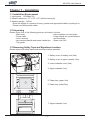
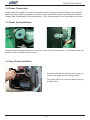
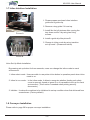
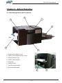
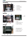
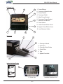
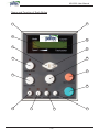
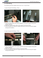
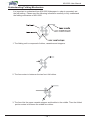
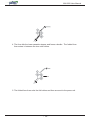
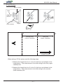
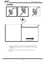
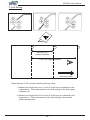
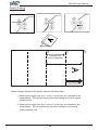
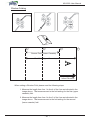
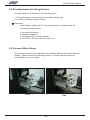
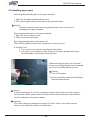
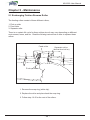
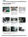
MX-6000 User Manual
Model MX-6000
User Manual
Rev. 070119
MX-6000 User Manual
Greeting
Thank you for purchasing PAITEC USA products.
This manual is prepared to provide guidelines on how to properly operate and maintain
MX-6000.
Copyright
Any of the contents should not be copied, re-printed or translated by other languages
without PAITEC USA approval.
Notice
Caution : Physical injury and serious mechanical damage will occur when
disregarding this information.
Important : This information is contained with useful information and guidance.
Reference : This information guides the chapter which detailed contents.
-1-
MX-6000 User Manual
Table of Contents
Chapter 1 - Installation
1-1 Installation Environment
1-2 Unpacking
1-3 Removing Safety Tapes and Styrofoam
1-4 Power Connection
1-5 Power Fan Installation
1-6 Tray Guide Installation
1-7 Online Interface Installation
1-8 Conveyor Installation
Chapter 2 - Before Operating
2-1 Identifying Parts
2-2 Caution for Installation
Chapter 3 - Preparing for Operation
3-1 Paper Size
3-2 Loading the Forms
3-3 Fold Setting
3-4 Fine Adjustment of Folding Position
3-5 Conveyor Wheel Setup
Chapter 4 - Handling Errors
4-1 Error Message
4-2 Handling Paper Jams
Chapter 5 - Maintenance
5-1 Exchanging Friction Reverse Roller
5-2 Cleaning Rollers
Chapter 6 - Troubleshooting
6-1 No Power
6-2 Incorrect Folding
6-3 Power On, but No Start
6-4 Frequent Double or Multiple Sheet Feeding
Chapter 7 - Conveyor
7-1 Conveyor Installation
-2-
MX-6000 User Manual
Chapter 1 - Installation
1-1 Installation Environment
1. Input power : 110V(Max 5A)
2. Machine size(mm) : 17" x 24" x 15" (without conveyor)
3. Machine weight : 143 lbs.
- Since the weight of a product is heavy, please use appropriate table for putting it on.
- Please use folded power cable.
1-2 Unpacking
Please check if all of the following parts are included in the box.
- Main body
- Inline interface unit and guide
- Power cable
- Power infeed fan, power adaptor
- User’s manual
and fix bracket
- Jam removal handle and spare handle tips - Spare fuse (8A)
- Tray guide
1-3 Removing Safety Tape and Styrofoam Location
Please remove all safety tapes and styrofoam before operation.
2
1. Safety cover of feeding unit (2ea)
1
2. Safety cover of upper cassette (2ea)
4
3. Lower cassette cover (2ea)
3
4. Upper cassette (1ea)
5. Paper tray (upper/1ea)
5
6. Paper tray (lower/2ea)
6
6
7
7. Upper cassette (1ea)
-3-
MX-6000 User Manual
1-4 Power Connection
Please refer to the label for electric information which is located at the back side of the machine.
When the power cable is properly connected, please switch the machine on and check whether
‘Ready’ sign is displayed on the display panel. If not, please contact your local dealer for service.
1-5 Power Fan Installation
Please attach the power infeed fan at the rear cover like the picture above. The power infeed fan
allows smoother infeeding of the forms.
1-6 Tray Guide Installation
Please install like the left picture by using enclosed tray guide and two fixing screws.
Tray guide has to be removed when using the
printer online.
-4-
MX-6000 User Manual
1-7 Inline Interface Installation
1. Please prepare enclosed inline interface
guide and a guide clip.
2. Remove a tray guide if it is set up.
Picture A
3. Install like the left pictures after moving the
tray down and fix it by using two fixing
screws.
4. Install a guide clip like picture B.
5. Change to inline mode by using ‘machine
set up mode’. (Please see below)
Picture B
Inline Set Up Mode Installation
By pressing set-up button for three seconds, users can change the inline mode to users’
environment.
1. Inline select mode : Users are able to use printer inline button in operation panel when inline
mode is on.
2. Inline lct cov mode : In the inline mode, it ables to recognize whether feeding unit safety
cover is opened, closed or ignore it so it is possible to set up for users’
environment. (This function is needed when printing security
documents.)
3. Initialize : It makes the machine to be initialized to set-up condition when first delivered from
a warehouse. (Factory default)
1-8 Conveyor Installation
Please refer to page 28 for proper conveyor installation.
-5-
MX-6000 User Manual
Chapter 2 - Before Operating
2-1 Identifying Parts and Functions
6
2
1
5
3
4
1. Feeding Unit Safety Cover
2. Upper Fold Cassette Safety Cover
3. Large Capacity Tray
4. Lower Fold Cassette
5. Conveyor
6. Control Panel
7. Jam Removal Handle
8. Serial Number Label
8
-6-
7
MX-6000 User Manual
Large Capacity Tray
5
6
4
1. Tray Guide
2. Feed Guide (Left)
3
3. Feed Guide (Right)
4. Locking Knob
5. Infeed Roller
1
6. Tray Level Sensor
2
Lower Cassette
4
1
5
1. Lower Cassette
2. Stopper
3. Stopper Adjustment Knob
2
3
4. Folding Scale Label
Upper Cassette
5. Stopper Locking Knob
1
4
1. Upper Cassette Handle
2. Folding Scale Label
3. Stopper Adjustment Knob
4. Stopper Locking Knob
5. Fold Position Marker
5
2
3
-7-
MX-6000 User Manual
Outfeed Unit
10
1
2
1. Press Rollers
3
2. Conveyor Wheel Holder
3. Power Switch
4
4. Conveyor Shaft
5. Main Power Socket
6. Conveyor Power Socket
11
7. Manual Feed Button
8. Fuse Socket
9. Lower Press Roller Cover
5
10. Upper Press Roller Cover
11. Jam Removal Holes
7
9
6
8
Conveyor
1
2
3
1. Conveyor Wheel
2. Conveyor
3. Conveyor Side Guide
4
4. Guide Wire
5. Tray
6. Speed Controller
5
6
Inline interface Guide
1
Guide Clip
1. Guide Clip
-8-
Installed Interface Unit
MX-6000 User Manual
Name and Function of Each Button
15
1
2
14
3
13
4
12
11
5
10
6
7
8
-9-
9
MX-6000 User Manual
1. Mode - Displays current status of the machine.
2. Speed - Displays the machine’s current set speed.
3. ( - ) Button - Decreases the speed or value.
4. Printer Inline Button - Changes to online/offline mode. (operable only at online
mode)
5. Batch Counter Button - You can set the number of forms that you wish to process and
have the machine stop automatically until you press the start button. For example, if
you set the batch counter at 100, after 100 forms are processed, the machine will
automatically stop and will not start until you press the start button.
- Press the batch counter button and the light will blink.
- Change the displayed value by using +/- button and when ready, press the set
button.
- When changing the value, press the batch counter button to increase the value
by 50 up to 500.
- This setting is not stored after rebooting the machine.
6. Thickness Sensor Button - Thickness sensor function allows you to prevent any
serious paper jams caused by double feeding or multiple sheet feeding.
- Press the thickness sensor button and one form will feed.
- The form stops and is scanned by the thickness sensor.
- After the reading is completed, the form then processes through.
- The LED light will remain on and your desired thickness is stored in the setting.
- Feeding of any forms outside of the calibrated setting will stop the machine from
further processing while using this function.
Reference
- Whenever you change to a different form, please reset the thickness
value by following the steps indicated above.
- Using the same setting with a different paper will stop the machine as the
form will be recognized as a double feed.
7. Jam Free Button - Clears any jam in the press roller unit.
Important
- Jam free function will not clear all jams. If a jam is not cleared with this function,
please refer to the next chapter on handling errors.
- 10 -
MX-6000 User Manual
8. Auto Start Button - You can choose to separate your job by using the ‘Auto Start’
function. You can simply set your desired volume per run and the time interval in
between run. For example, if you set the counter at 50 and auto start at 5 seconds,
the machine will run 50 forms and stops for five seconds until it starts again to process
50 forms and so on. (Available only when using batch counter function)
- Press the auto start button while the batch counter button is on.
- Change the time interval by using +/- button from 1 to 99.
- After the setting is ready, press the set button to store the setting.
9. Manual Feed Button - Allows the processing of single damaged forms.
- Press the manual feed button on the control panel.
- Place the folded form at the entrance of the outfeed on the conveyor.
- Then press the second manual button (red button located at the front cover).
Important
- Please do not release the manual feed button on
the control panel until the job is completed.
- In case you release the manual feed button and
the panel reads ‘stacker full’, press the jam free
button to clear the form from the press rollers.
10. Start/Stop Button - Start or stops the machine.
11. Reset Counter Button - Clears the count on the display panel.
12. Set Button - Stores any value or setting.
13. (+) Button - Increases the speed or value.
14. Total Counter - Displays the total count of the machine.
15. Counter - Displays the current count of the machine.
- 11 -
MX-6000 User Manual
Chapter 3 - Preparing for operation
3-1 Paper Size
Postmate 6 handles any form that is larger or smaller than the following forms.
210
357
148
264
Reference
- Using forms that do not fall under the specified size may result in paper
jam or machine damage.
Important
- Please check whether any forms are stapled. Staples will seriously damage
the machine.
3-2 Loading the Forms
1. Before loading the forms onto the machine, please make sure all forms are aligned and
fanned. Please refer to the images below.
Good
Bad
If the condition of forms are not good as the picture above (Bad), place appropriate quantity of forms, unless forms will be jammed.
- 12 -
MX-6000 User Manual
2. Open the safety cover of the feeding unit. The tray will go down.
3. When the feed tray is down to the bottom, loosen the green knobs on both paper
guides.
4. Load the aligned forms onto the feed tray and adjust the paper guides so they
are gently covering the sides of the stacked forms.
5. Tighten back the green knobs on both paper guides.
6. Once loading is complete, please close the safety cover. The feed tray will go
up.
Caution
- Poor quality forms may cause frequent paper jams.
- Make sure the paper guides are not set narrower or wider than the width of
the paper.
Reference
- When the forms are fed into the machine, all forms go to the upper
cassette and then to the lower cassette.
- Please refer to the images below to understand more about the path in
which the forms are folded.
Caution
- Please do not place any
objects that may cover the
sensor as indicated in the
picture.
Good
- 13 -
Bad
MX-6000 User Manual
3-3 Fold Setting
The following instruction shows how to set 8 1/2 X 11 size Z-Fold.
1. Lower Cassette Fold Setting - 93mm
1. Unlock the fold position of the lower cassette by turning the stopper locking knob
counter clockwise.
2. Adjust the stopper so the surface of the rubber is lined up at 93mm.
3. Lock the stopper by holding the stopper adjustment knob and turning the stopper
locking knob clockwise.
2. Upper Cassette Fold Setting - 93mm
1. Unlock the fold position of the upper cassette by turning the stopper locking knob
counter clockwise.
2. Adjust the stopper so the red marker is lined up at 93mm.
3. Lock the stopper by holding the stopper adjustment knob and turning the stopper
locking knob clockwise.
- 14 -
MX-6000 User Manual
Understanding Folding Mechanism
It is important to understand how MX-6000 folds paper in order to accurately set
the fold setting. Please read the following information carefully to fully understand
the folding mechanism of MX-6000.
1. The folding unit is composed of rollers, cassettes and stoppers.
2. The form enters in between the two front fold rollers.
3. The form hits the upper cassette stopper and buckles in the middle. Then the folded
portion enters in between the middle two rollers.
- 15 -
MX-6000 User Manual
4. The form hits the lower cassette stopper and forms a buckle. The folded form
then enters in between the two outer rollers.
5. The folded form then exits the fold rollers and then are sent to the press unit.
- 16 -
MX-6000 User Manual
Z-Fold Setting
Upper Cassette
Paper
Infeed
Direction
Outfeed
Direction
Stopper
A
Lower Cassette
2
3
First Fold
(Upper Cassette)
A
Second Fold
(Lower Cassette)
1
Infeed Direction
When setting a Z-Fold, please read the following steps.
1. Measure the length from line 1 to line 2 of the form as indicated in the
image above. That measurement is the fold setting for the first (upper
cassette) fold.
2. Measure the length from line 2 to line 3 of the form as indicated in the
image above. That measurement is the fold setting for the second
(lower cassette) fold.
- 17 -
MX-6000 User Manual
V-Fold Setting
A
V-Fold Guide
2
1
First Fold (Upper Cassette)
Infeed Direction
When setting a V or a Single-Fold, please read the following steps.
1. Measure the length from line 1 to line 2 of the form as indicated in the
image above. That measurement is the fold setting for the first (upper
cassette) fold.
2. Make sure the V-fold guide is placed at the entrance of the lower
cassette.
- 18 -
MX-6000 User Manual
A
C-Fold Setting
2
3
1
Second Fold
(Lower Cassette)
A
First Fold (Upper Cassette)
Infeed Direction
When setting a C-Fold, please read the following steps.
1. Measure the length from line 1 to line 3 of the form as indicated in the
image above. That measurement is the fold setting for the first (upper
cassette) fold.
2. Measure the length from line 3 to line 2 of the form as indicated in the
image above. That measurement is the fold setting for the second
(lower cassette) fold.
- 19 -
MX-6000 User Manual
A
Double Folding
2
3
1
Second Fold
(Lower Cassette)
First Fold (Upper Cassette)
A
Infeed Direction
When setting a Double-Fold, please read the following steps.
1. Measure the length from line 1 to line 3 of the form as indicated in the
image above. That measurement is the fold setting for the first (upper
cassette) fold.
2. Measure the length from line 3 to line 2 of the form as indicated in the
image above. That measurement is the fold setting for the second
(lower cassette) fold.
- 20 -
MX-6000 User Manual
A
Window Folding
4
2
3
1
Second Fold (Lower Cassette)
First Fold (Upper Cassette)
A
Infeed Direction
When setting a Window-Fold, please read the following steps.
1. Measure the length from line 1 to line 4 of the form as indicated in the
image above. That measurement is the fold setting for the first (upper
cassette) fold.
2. Measure the length from line 4 to line 2 of the form as indicated in the
image above. That measurement is the fold setting for the second
(lower cassette) fold.
- 21 -
MX-6000 User Manual
3-4 Fine Adjustment of Folding Position
You can adjust the fold setting in the following cases.
1. Fine adjustment is required from the standard folding type.
2. In case the folding is slightly different.
Reference
If the folding is slightly off from the desired position, please check the
following possible causes.
a. Incorrect fold setting
b. Machine clearance
c. Incorrect position of fold cassettes
d. The FRR or the fold rollers are worn out
3-5 Conveyor Wheel Setup
The conveyor wheel can be adjusted to accomodate different forms with different
lengths. Please refer to the following pictures to correctly set the wheels to
accomodate your form lengths.
Good
Bad
- 22 -
MX-6000 User Manual
Chapter 4 - Handling Errors
4-1 Error Message
There are various types of sensors located at different parts of MX-6000. These
sensors detect and display the location of an error on the panel. Please read the
following errors to understand how to handle each error.
Error Message
Miss feeding
Jam infeed sensor
When a form does not reach the infeed sensor after
infeed.
When a form is jammed at the infeed sensor.
Jam folder
When a form is jammed at the folding unit.
Press jam
When a form is jammed at the press unit.
Stacker full
When the stacker is full and the last form is detected
by the outfeed sensor.
Paper thickness err
When the paper thickness cannot detect the thickness
of the form being scanned by the thickness sensor.
Lower cassette missing
When the lower cassette is not closed all the way.
Out of paper
When there are no forms on the paper tray or the
paper sensor is not detecting any forms.
Right cover open
When the upper cassette safety cover is opened.
Left cover open
When the feeding unit safety cover is opened.
- 23 -
MX-6000 User Manual
4-2 Handling paper jams
Removing the jammed paper at the upper cassette
1. Open the top upper cassette safety cover.
2. Pull out the upper cassette and remove any jammed paper.
Caution
Please be cautious when removing jammed forms as it may result in
damaging the upper cassette.
Removing jammed paper at the lower cassette
1. Open the lower cassette cover.
2. Remove any jammed paper.
Removing jammed paper at the press unit.
There can be different reasons for a paper jam at the press unit.
A. Double Feed
1. Try to remove the jam by using the jam free button.
2. If the jam is not cleared by using the jam free button, please use the jam
removal handle to manually remove the jam.
When removing the jam, turn the press
rollers by inserting the jam removal handle
and turn it clockwise like the picture.
Caution
1. Turn off the power.
2. Never operate the machine with the jam
removal handle set up.
Caution
- If the jammed paper is too thick to pass through the press roller even by using the
jam removal handle, please turn the handle in the reverse direction of the direction
which is indicated in the picture above.
Important
- The press rollers are designed to accept 16~29 lbs. forms. Any forms that are
heavier may affect the machine to malfunction.
- 24 -
MX-6000 User Manual
Chapter 5 - Maintenance
5-1 Exchanging Friction Reverse Roller
The feeding rollers consist of three different rollers;
1. Pick up roller
2. Feed roller
3. Separate roller
There is no certain life cycle for these rollers since it may vary depending on different
environment, forms, and etc. Read the follwing instructions on how to replace these
rollers.
Feed roller
Separate roller
(below feed roller)
Pick-up roller
1. Remove the snap ring (white clip).
2. Replace the roller and place back the snap ring.
3. Follow step 1 & 2 for the rest of the rollers.
- 25 -
MX-6000 User Manual
5-2 Cleaning Rollers
Since Pressure seal forms leave paper dust, ink and toner residues, it is very
important to occasionally clean the surface of the each roller to maintain its best
condition for better performance.
1. Paper dust
- Use small air cleaner or dust remover.
2. Cleaning fold rollers
- Open the safety cover and slide out the upper cassette. With a piece of
soft cloth, use alcohol or water to remove any ink contamination or toner
residues on the surface of the fold rollers.
Caution - Please do not use any other substance when cleaning the surface of
the fold rollers as it may damage the rubber.
3. Cleaning press rollers
- A professional’s aid is necessary to clean press rollers. Try to clean it by
an engineer’s help, if possible. If you are going to do it by yourself, please
turn of the power.
- Remove conveyor wheel holder, lower press roller cover and upper press
press roller cover in the picture below.
- Two rollers and inner lower press roller shown in picture A can be cleaned.
- Inner upper roller can be cleaned like picture B.
Picture B
Picture A
- 26 -
MX-6000 User Manual
Chapter 6 - Troubleshooting
Some of the errors can easily be fixed by the user without a professional’s aid.
6-1 No Power
1. Check whether the power cable is properly connected.
2. Check the power supply.
6-2 Incorrect Folding
1. Please check whether the fold position is correct.
6-3 Power On, but No Start
1. Check if the left safety cover is opened.
2. Check if the right safety cover is opened.
3. Check if the lower cassette is pushed all the way in.
4. Check for any paper jams.
6-4 Frequent Double or Multiple Sheet Feeding
1. Exchange all three rollers all at once. They are probably worn-out.
2. Check whether the adhesive paper is too thick or strong.
3. Check whether the forms are lighter than 16 lbs.
4. Check whether the infeed tray guide is set correctly.
- 27 -
MX-6000 User Manual
Chapter 7 - Conveyor (Optional)
7-1 Conveyor Installation
1.
2.
Please attach the tray to
the main body of the
conveyor like the picture.
4.
3.
5.
Place the conveyor
on to the shaft like the
picture.
Please attach the lower
bracket like the picture.
Please loosen the screws
and attach the side guide
on both sides by using
the same screws like the
picture.
6.
Please tighten the two
screws to fix the
conveyor to the main
body.
Please attach the
wheels on to the holder
like the picture.
8.
7.
The conveyor wheel can be adjusted to accomodate
different forms with different lengths. Please refer to the
following pictures to correctly set the wheels to
accomodate your form lengths.
- 28 -
Completed.
MX-6000 User Manual
This page intentionally left blank
Headquarters & Factory
15951 SW 41st Street Suite 400
Davie, FL 33331
E-mail [email protected]
Website : www.paitec.com
- 29 -