1
ICC
Instruction Manual
INDUSTRIAL CONTROL COMMUNICATIONS, INC.
MA7200-1000
Multiprotocol RS-485 Interface
Card for MA7200 Drives
December 1, 2009
ICC #10761
© 2009 Industrial Control Communications, Inc.
MA7200-1000
User's Manual
Part Number 10761
Printed in U.S.A.
©2009 Industrial Control Communications, Inc.
All rights reserved
NOTICE TO USERS
Industrial Control Communications, Inc. reserves the right to make changes and
improvements to its products without providing notice.
Industrial Control Communications, Inc. shall not be liable for technical or editorial
omissions or mistakes in this manual, nor shall it be liable for incidental or
consequential damages resulting from the use of information contained in this
manual.
INDUSTRIAL CONTROL COMMUNICATIONS, INC.’S PRODUCTS ARE NOT
AUTHORIZED FOR USE AS CRITICAL COMPONENTS IN LIFE-SUPPORT
DEVICES OR SYSTEMS. Life-support devices or systems are devices or
systems intended to sustain life, and whose failure to perform, when properly
used in accordance with instructions for use provided in the labeling and user's
manual, can be reasonably expected to result in significant injury.
No complex software or hardware system is perfect. Bugs may always be present
in a system of any size. In order to prevent danger to life or property, it is the
responsibility of the system designer to incorporate redundant protective
mechanisms appropriate to the risk involved.
This user’s manual may not cover all of the variations of interface applications,
nor may it provide information on every possible contingency concerning
installation, programming, operation, or maintenance.
The contents of this user’s manual shall not become a part of or modify any prior
agreement, commitment, or relationship between the customer and Industrial
Control Communications, Inc. The sales contract contains the entire obligation of
Industrial Control Communications, Inc. The warranty contained in the contract
between the parties is the sole warranty of Industrial Control Communications,
Inc., and any statements contained herein do not create new warranties or modify
the existing warranty.
Any electrical or mechanical modifications to this equipment without prior written
consent of Industrial Control Communications, Inc. will void all warranties and
may void any UL/cUL listing or other safety certifications. Unauthorized
modifications may also result in equipment damage or personal injury.
APPLICABLE FIRMWARE
For applicable firmware, please refer to the XLTR-1000 Instruction Manual.
2
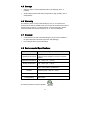
Usage Precautions
Operating Environment
•
Please use the interface only when the ambient temperature of the
environment into which the unit is installed is within the following
specified temperature limits:
Operation: -10 ∼ +50°C (+14 ∼ +122°F)
-40 ∼ +85°C (-40 ∼ +185°F)
Storage:
•
Avoid installation locations that may be subjected to large shocks or
vibrations.
Avoid installation locations that may be subjected to rapid changes in
temperature or humidity.
•
Installation and Wiring
•
•
Proper ground connections are vital for both safety and signal reliability
reasons. Ensure that all electrical equipment is properly grounded.
Route all communication cables separate from high-voltage or noiseemitting cabling (such as ASD input/output power wiring).
3
TABLE OF CONTENTS
1.
Introduction .................................................................................. 5
2.
Features ........................................................................................ 6
3.
Interface Card Concepts ............................................................. 8
4.
Precautions and Specifications.................................................. 9
4.1
4.2
4.3
4.4
4.5
4.6
4.7
4.8
5.
5.1
5.2
6.
6.1
6.2
6.3
6.4
7.
7.1
7.2
Installation Precautions .........................................................................9
Maintenance Precautions ....................................................................10
Inspection ............................................................................................10
Maintenance and Inspection Procedure ..............................................10
Storage................................................................................................11
Warranty..............................................................................................11
Disposal ..............................................................................................11
Environmental Specifications ..............................................................11
Interface Card Overview ............................................................ 12
Power Supply Electrical Interface ........................................................13
RS-485 Port Electrical Interface ..........................................................13
Installation .................................................................................. 14
Internal Mounting.................................................................................14
External Mounting ...............................................................................14
Wiring Connections .............................................................................15
Grounding............................................................................................15
LED Indicators ............................................................................ 16
Module Status .....................................................................................16
RS-485 Network Status LEDs .............................................................16
8.
Drive Parameter Configuration ................................................. 17
9.
Quick-Start Configuration ......................................................... 19
10.
Predefined Configuration Files............................................. 24
10.1
10.2
BACnet MS/TP Server ........................................................................24
Johnson Controls Metasys N2.............................................................28
4
1. Introduction
Congratulations on your purchase of the ICC MA7200-1000 multiprotocol RS-485
interface card for the Teco-Westinghouse MA7200 adjustable-speed drive family.
This interface card allows the MA7200 drive to be directly connected to various
RS-485 communication networks, such as BACnet MS/TP and Johnson Controls
Metasys N2. In addition to the supported fieldbus protocols, the interface card
hosts a USB interface for configuring the card via a PC.
Before using the interface card, please familiarize yourself with the product and
be sure to thoroughly read the instructions and precautions contained in this
manual. In addition, please make sure that this instruction manual is delivered to
the end user of the drive and interface card, and keep this instruction manual in a
safe place for future reference or unit inspection.
For the latest information, support software and firmware releases, please visit
http://www.iccdesigns.com.
Before continuing, please take a moment to ensure that you have received all
materials shipped with your kit. These items are:
•
•
•
MA7200-1000 interface card
Documentation CD-ROM
3 nylon standoffs
Note that different interface card firmware versions may provide varying levels of
support for the various protocols. When using this manual, therefore, always
keep in mind that the firmware version indicated on your unit must be listed on
page 2 for all documented aspects to apply.
This manual will primarily be concerned with the interface card’s hardware
specifications, installation, wiring, configuration and operational characteristics.
To maximize the abilities of your new interface card, a working familiarity with this
manual will be required. This manual has been prepared for the interface card
installer, user, and maintenance personnel. With this in mind, use this manual to
develop a system familiarity before attempting to install or operate the interface
card and drive system.
Note that because the MA7200-1000 is a derivative product of the ICC XLTR1000 multiprotocol RS-485 network gateway, this instruction manual will not
duplicate the majority of the configuration and operation information already
contained in the XLTR-1000 Instruction Manual. A proper understanding of the
MA7200-1000, therefore, relies in part on a thorough understanding of the
contents of the XLTR-1000 Instruction Manual.
5
2. Features
Supported Protocols
The interface card currently provides support for the following fieldbus protocols:
•
Modbus RTU Master
•
Modbus RTU Slave
•
BACnet MS/TP Client
•
BACnet MS/TP Server
•
Johnson Controls Metasys N2 Slave
Note that any combination of these protocols may be configured on the interface
card’s “RS-485 A (NETWORK)” and “RS-485 B (INVERTER)” ports. Typically,
however, the “RS-485 B (INVERTER)” port will be configured as a Modbus RTU
master port (to communicate to the MA7200 drive), while the “RS-485 A
(NETWORK)” port will be configured for the building network protocol in use.
A Member of the ICC Millennium Series Family
The interface card is a member of the ICC Millennium Series family of
communication products. As such, it is able to take advantage of the ICC
Gateway Configuration utility, and uses the same network drivers as the standard
ICC XLTR-1000 multiprotocol network gateway.
Both Client and Server Functionality
The interface card provides the ability to act as a traditional slave/server device
on the fieldbus network (drive mode). However, it is also possible to configure
the card to act as a client/master on certain networks (scanner mode), which
allows the card to scan remote I/O on its own (perhaps from various sensors,
other drives, etc.). This data can then be scaled if desired and passed on to the
attached drive, thereby eliminating the necessity of a separate network master to
reside on the network, exchanging information among groups of slaves.
Supported Baud Rates
The interface card currently provides support for the following baud rates:
•
2400
•
4800
•
9600
•
19200
•
38400
•
57600
•
76800
•
115200
Note that not all protocols support every baud rate listed above. Refer to the
XLTR-1000 Instruction Manual for more information.
6
Field-Upgradeable
As new firmware becomes available, the interface card can be upgraded in the
field by the end-user. Refer to the XLTR-1000 Instruction Manual for more
information.
USB Interface
The interface card can be connected to a PC via a USB mini type-B cable. This
simultaneously supplies power while providing the ability to configure the
interface card, monitor data, and update firmware on the device using the ICC
Gateway Configuration Utility. Refer to the XLTR-1000 Instruction Manual for
more information.
7
3. Interface Card Concepts
The MA7200-1000 is a derivative product of the ICC XLTR-1000 multiprotocol
RS-485 network gateway. While the MA7200-1000 has been adapted for specific
application to the Teco-Westinghouse MA7200 family of drives, it is still
fundamentally a XLTR-1000 gateway device at its core. This means that the
MA7200-1000 enumerates itself to the ICC Gateway Configuration Utility as a
standard XLTR-1000 gateway, uses all existing XLTR-1000 firmware drivers, and
is otherwise configured in an identical manner to the XLTR-1000 gateway.
While ICC provides certain “standard” configuration files for typical MA7200-1000
applications on popular fieldbus networks, these configuration files are still
entirely user-configurable, allowing end-users to add/remove/change data items
and configuration elements to suit their specific application. For detailed
instructions regarding how to modify the network configuration elements, please
refer to the XLTR-1000 Instruction Manual.
The XLTR-1000 gateway is a 2-port RS-485 device, whose two ports are labeled
“RS-485 A” and “RS-485 B”. These same two ports exist on the MA7200-1000’s
terminal block, and are labeled on the adjacent silkscreen to clearly identify which
port is being configured: “RS-485 A (NETWORK)” and “RS-485 B (INVERTER)”.
The only other main distinction between the XLTR-1000 gateway and the
MA7200-1000 interface card is that the MA7200-1000’s RS-485 ports are both
only 2-wire interfaces (instead of the 2- or 4-wire interfaces available on the
XLTR-1000).
Configuration of the MA7200-1000 can be performed at a workstation, prior to
installation of the card into a drive. In this scenario, the interface card will draw
power from an attached USB cable, and therefore requires no additional power
supply when attached to a computer’s USB port. Of course, it is also possible to
configure the interface card after it has been installed into an inverter.
The remainder of this instruction manual will deal with items that are specific to
the MA7200-1000 interface card. For all other information that is common to the
XLTR-1000 gateway (such as network configuration, explanation of configuration
fields, etc.), please refer to the XLTR-1000 Instruction Manual.
8
4. Precautions and Specifications
Rotating shafts and electrical equipment can be hazardous.
Installation, operation, and maintenance of the interface card shall
be performed by Qualified Personnel only.
Qualified Personnel shall be:
• Familiar with the construction and function of the interface card
and the drive into which it is installed, the equipment being
driven, and the hazards involved.
• Trained and authorized to safely clear faults, ground and tag
circuits, energize and de-energize circuits in accordance with
established safety practices.
• Trained in the proper care and use of protective equipment in
accordance with established safety practices.
Installation of the interface card should conform to all applicable
National Electrical Code (NEC) Requirements For Electrical
Installations, all regulations of the Occupational Safety and
Health Administration, and any other applicable national, regional,
or industry codes and standards.
DO NOT install, operate, perform maintenance, or dispose of this
equipment until you have read and understood all of the following
product warnings and user directions. Failure to do so may result in
equipment damage, operator injury, or death.
4.1 Installation Precautions
• Avoid installation in areas where vibration, heat, humidity, dust,
metal particles, or high levels of electrical noise (EMI) are
present.
• Do not install the interface card where it may be exposed to
flammable chemicals or gasses, water, solvents, or other fluids.
• Follow all warnings and precautions and do not exceed
equipment ratings.
9
4.2 Maintenance Precautions
• Do Not attempt to disassemble, modify, or repair the interface
card. Contact your ICC or Teco-Westinghouse support
representative for repair or service information.
• If the interface card should emit smoke or an unusual odor or
sound, turn the power off immediately.
• The system should be inspected periodically for damaged or
improperly functioning parts, cleanliness, and to determine that
all connectors are tightened securely.
4.3 Inspection
Upon receipt, perform the following checks:
•
Inspect the unit for shipping damage.
•
Check for loose, broken, damaged or missing parts.
Report any discrepancies to your ICC or Teco-Westinghouse support
representative.
4.4 Maintenance and Inspection Procedure
Preventive maintenance and inspection is required to maintain the interface card
in its optimal condition, and to ensure a long operational lifetime. Depending on
usage and operating conditions, perform a periodic inspection once every three
to six months.
Inspection Points
•
Check that there are no defects in any attached wire terminal crimp points.
Visually check that the crimp points are not scarred by overheating.
•
Visually check all wiring and cables for damage. Replace as necessary.
•
Clean off any accumulated dust and dirt.
•
If use of the interface card is discontinued for extended periods of time, apply
power at least once every two years and confirm that the unit still functions
properly.
•
Do not perform hi-pot tests on the interface card, as they may damage the
unit.
Please pay close attention to all periodic inspection points and maintain a good
operating environment.
10
4.5 Storage
•
Store the device in a well ventilated location (in its shipping carton, if
possible).
•
Avoid storage locations with extreme temperatures, high humidity, dust, or
metal particles.
4.6 Warranty
This interface card is covered under warranty by ICC, Inc. for a period of 12
months from the date of installation, but not to exceed 18 months from the date of
shipment from the factory. For further warranty or service information, please
contact Industrial Control Communications, Inc. or your local distributor.
4.7 Disposal
•
Contact the local or state environmental agency in your area for details on
the proper disposal of electrical components and packaging.
•
Do not dispose of the unit via incineration.
4.8 Environmental Specifications
Item
Specification
Operating Environment
Indoors, less than 1000m above sea level, do not
expose to direct sunlight or corrosive / explosive
gasses
Operating Temperature
-10 ∼ +50°C (+14 ∼ +122°F)
Storage Temperature
-40 ∼ +85°C (-40 ∼ +185°F)
Relative Humidity
20% ∼ 90% (without condensation)
Vibration
5.9m/s2 {0.6G} or less (10 ∼ 55Hz)
Grounding
Cooling Method
Non-isolated, referenced to power ground
Self-cooled
This device is lead-free / RoHS-compliant.
11
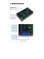
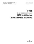
5. Interface Card Overview
Standoff Mounting
Holes (x3)
Terminal block
USB connector
Interface Card Overview
Inverter RS-485
Terminals (RS-485 B)
Network RS-485
Terminals (RS-485 A)
Network TX/RX LEDs
Power Terminals
Inverter TX/RX LEDs
Module Status LED
Interface Card Details
12
5.1 Power Supply Electrical Interface
When the interface card is not plugged into a PC via the USB cable, it must be
powered by an external power source. Ensure that the power supply adheres to
the following specifications:
Voltage rating ......................... 5 - 24VDC
Minimum Current rating .......... 50mA (@24VDC)
•
Typical current consumption of the MA7200-1000 when powered from a 24V
supply is approximately 15mA.
•
Do not attempt to power the interface card from the drive’s “+12V” supply
terminal, as this terminal does not provide sufficient current.
•
ICC offers an optional 120VAC/12VDC power supply (ICC part number
10755) that can be used to power the interface card from a standard wall
outlet.
•
The power supply must be connected to terminals “VCC” and “GND”
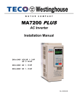
5.2 RS-485 Port Electrical Interface
In order to ensure appropriate network conditions (signal voltage levels, etc.)
when making connections to the interface card’s “Network / RS-485 A” port,
some knowledge of the network interface circuitry is required. Refer to Figure 1
for a simplified network schematic of the RS-485 interface circuitry. Note that the
circuitry for the “Network / RS-485 A” port is not the same as that for the “Inverter
/ RS-485 B” port, and the connections for these ports are therefore not
interchangeable.
The GND terminal should also be used to connect the network ground wire.
Figure 1: RS-485 Interface Circuitry Schematic
13
6. Installation
The interface card’s installation procedure will vary slightly depending on the size
of the drive to which it is to be connected.
•
For 3HP and larger MA7200 drives, the interface card mounts directly onto
the drive’s control board via the three included nylon standoffs.
•
For smaller drives, the interface card must be mounted externally (on a
panel, etc.)
6.1 Internal Mounting
On 3HP and larger drives, install the three included nylon standoffs into the
corresponding holes on the drive’s control board, then install the interface card
onto the standoffs.
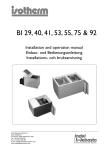
6.2 External Mounting
On drives smaller than 3HP, the
interface card must be externally
mounted. Refer to Figure 2 for
a dimensional drawing of the
locations of the standoff holes
(4mm diameter) to be drilled into
the mounting panel. Use
appropriate hardware (not
included) to attach the interface
card to the mounting panel.
The included nylon standoffs
may be used to mount the
interface card to the panel if a
4mm drill bit is used, and the
thickness of the panel is
approximately equivalent to the
thickness of a typical PCB
(0.0625” / 1.6mm).
Figure 2: External Mounting Diagram
14
6.3 Wiring Connections
1.
Mount the interface card via the desired method, depending on the drive’s
capacity (refer to sections 6.1 or 6.2).
2.
Connect the RS-485 B (INVERTER) terminals to the indicated “S(+)” and
“S(-)” RS-485 terminals on the MA7200 drive.
3.
Connect the network wiring to the RS-485 A (NETWORK) terminals.
Connect the network GROUND wire to the same GND terminal used by the
interface card’s power supply.
4.
Connect the power supply to the VCC and GND terminals as indicated on
the interface card’s silkscreen. Pay particular attention to the proper polarity.
5.
Take a moment to verify that the power and communication cables have
sufficient clearance from electrical noise sources such as motor wiring or
power-carrying electrical wiring. Also ensure that all wires are fully seated
into their respective terminal blocks, and that they are routed away from any
sharp edges or positions where they may be pinched.
6.4 Grounding
Grounding is of particular importance for reliable, stable operation.
Communication system characteristics may vary from system to system,
depending on the system environment and grounding method used. The
interface card has a single GND terminal that serves as the ground reference for
both power and RS-485 A (NETWORK) communication signals.
Please be sure to consider the following general points for making proper ground
connections:
Grounding method checkpoints
1. Make all ground connections such that no ground current flows through the
case or heatsink of a connected electrical device.
2. Do not connect the GND terminal to a drive power ground or any other
potential noise-producing ground connection.
3. Do not make connections to unstable grounds (paint-coated screw heads,
grounds that are subjected to inductive noise, etc.)
15
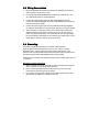
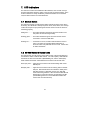
7. LED Indicators
The interface contains several different LED indicators, each of which conveys
important information about the status of the unit and connected networks. Each
of these indicators is clearly identified by a silkscreened label on the interface
card, and their functions are summarized here.
7.1 Module Status
The interface card has one dichromatic LED to indicate the status of the device.
On startup, the LED blinks a startup sequence: Green, Red, Green, Red. Always
confirm this sequence upon powering the interface card to ensure the device is
functioning properly.
Solid green ............. The status LED lights solid green when the interface card
has power and is functioning normally.
Flashing green........ The status LED flashes green when the interface card is
connected to a PC via a USB cable.
Flashing red............ If a fatal error occurs, the status LED will flash a red error
code. The number of sequential blinks (followed by 2
seconds of OFF time) indicates the error code. Contact ICC
for further assistance.
7.2 RS-485 Network Status LEDs
The interface has one red and one green LED for each of the two RS-485 ports
to indicate the status of that RS-485 network. The “485 A (NET)” LEDs indicate
the transfer of data on the RS-485 A (NETWORK) port, and the “485 B (INV)”
LEDs indicate the transfer of data between the interface card and the drive.
Green (TX) LED ..... Lights when the interface card is transmitting data on that
RS-485 port.
Red (RX) LED ........ Lights when the interface card is receiving data on that RS485 port. Note that this does not indicate the validity of the
data with respect to a particular protocol: only that data
exists and is being detected. Also note that the RX LED will
always light in conjunction with the corresponding TX LED
(as transmitting devices on 2-wire RS-485 networks also
receive their own transmissions).
16
8. Drive Parameter Configuration
The interface card communicates to the drive via its standard RS-485 port with
the Modbus RTU protocol. Therefore, certain parameters (baud rate, etc.) on the
drive must be configured to match the interface card’s settings for communication
to be successful. In addition, there are other drive parameters that may or may
not be modified depending on, for example, whether or not the drive is to be
commanded from the network.
This section will detail some important considerations to make note of when
connecting to, and interacting with, the MA7200 drive.
•
Although the latest MA7200 Modbus manual (dated 2001/06/05) indicates
that the maximum baud rate (set via parameter Sn-37) is 9600 baud, all
newer drives actually support 19.2kbaud (Sn-37 = 4). For optimal data
throughput, it is recommended to use the fastest baud rate supported on
your drive.
•
When drive parameter Sn-38 (parity) is set to 0 (no parity), the interface
card’s RS-485 B (INVERTER) configuration can be set to either “No Parity (1
Stop Bit)” or “No Parity (2 Stop Bits)” (either setting will work).
•
Note that the default value of drive parameter Cn-27 (time-out check) is 1.0s.
If it is desired to disable communication timeout checking between the
interface card and the drive, set parameter Cn-27 to 0.0s.
•
If run/stop etc. commands are to come from network, set drive parameter
Sn-04 to 2.
•
If frequency reference is to come from network, set drive parameter Sn-05 to
2.
•
Note that the holding register “address” column provided in the MA7200
Modbus manual contains the Modbus “addressed as” (on-the-wire) values,
which are always 1 less than the Modbus “known as” values (which the ICC
Gateway Configuration Utility requires). Additionally, this “address” column
indicates the holding register numbers in hexadecimal, which is atypical for
Modbus decimal-based register assignments. Therefore, to calculate the
“register” assignment that must be programmed into the interface card’s
service object configuration, first convert the documented “address” to a
decimal value, and then add 1. For example, the MA7200’s “output
frequency” register is documented to exist at register 0025H. Converting this
number to decimal and adding 1 therefore results in a “known as” register
value of 38, which can then be entered in a service object’s “Start Reg”
configuration field.
•
The MA7200 drops Modbus packets frequently when it is in PRG mode,
which negatively impacts the overall quality of communications between the
interface card and the drive. Therefore, it is recommended to not leave the
drive in PRG mode for long periods of time unless absolutely necessary.
•
The MA7200 Modbus manual indicates that control data registers
(0000H..000FH) are read/write, but reading always returns 0. It is therefore
17
recommended that service objects targeting these registers have their “read”
function disabled.
•
All drive parameters may be read at any time, but only An and Bn
parameters can be written while the inverter is in DRV mode. The inverter
must be in PRG mode to write any other parameters.
•
Changes to the drive parameters that configure the RS-485 communication
characteristics (baud rate, etc.) do not take effect until the drive is reset.
•
Cn parameter changes take effect instantly, while others don't take effect
until the inverter is put back into DRV mode or the parameters are saved into
EEPROM and the inverter is reset.
•
The “write to EEPROM” register (0900H) is write-only. It is therefore
recommended that service objects targeting this register have their “read”
function disabled.
18
9. Quick-Start Configuration
This section will detail an example quick-start configuration procedure that loads
the predefined BACnet MS/TP configuration file onto the interface card. This
configuration procedure can either be done at a workstation (with the card
powered via the computer’s USB port) prior to installation into the drive, or it can
be performed once the card has already been installed in the drive.
Although this procedure will only demonstrate loading one of the predefined
configuration files (which map typically-used drive parameters to the fieldbus
network), it is perfectly acceptable to modify the predefined configuration files to
suit your specific application. For detailed procedures on how to modify protocol
object definitions, service objects etc., please refer to the XLTR-1000 Instruction
Manual.
For overviews of the predefined configuration file contents, refer to section 10.
1.
Connect the interface card to the computer via a USB mini type-B cable.
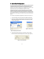
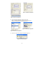
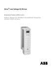
2.
Open the ICC Gateway Configuration Utility and select the XLTR-1000 via
either explicitly selecting the device (Figure 3) or by clicking on the “Auto
Connect” button (Figure 4).
Figure 4: Auto Connect
Figure 3: Explicitly Select Device
3.
Confirm that the status should now be “Connected”, and the on-board
firmware information should be displayed in the “Device” group (Figure 5).
Figure 5: Connected Status
19
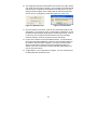
4.
Choose “Load Configuration” either via the “File…Load Configuration…”
menu (Figure 6), or by clicking on the folder icon in the toolbar (Figure 7).
This will load the predefined configuration file from your PC into the Gateway
Configuration Utility for manipulation and subsequent download to the
interface card.
Figure 7: Load Configuration
Figure 6: Load Configuration
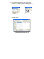
5.
Select the desired predefined configuration file and then click the “Open”
button. In this example, we will be selecting the predefined BACnet MS/TP
configuration (Figure 8).
Figure 8: Select Predefined Configuration File
20
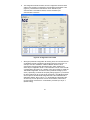
6.
The configuration file will be loaded, and the configuration elements will be
visible in the “RS-485 A Configuration” and “RS-485 B Configuration” tabs
(Figure 9). Remember that the interface card’s “RS-485 A” port
communicates to the fieldbus network, and the “RS-485 B” port
communicates to the drive.
Figure 9: Configuration File Loaded
7.
Although a predefined configuration file is being used, some minimal amount
of installation-specific configuration will still be required for each card. For
example, each drive installed on a BACnet MS/TP network must be
configured for the appropriate network baud rate, station address, and
device object configuration values. This information is found on the “RS-485
A Configuration” tab (Figure 10). Similarly, it may be necessary to adjust the
“RS-485 B Configuration” to match the drive’s parameter settings (or viceversa). Specifically, the baud rate and parity settings (Figure 11) must match
the drive’s settings for Sn-37 and Sn-38, respectively. Each Modbus master
service object on the RS-485 B configuration tab is also embedded with a
destination address, which is set to “1” in the predefined configuration files.
So that every service object does not have to be modified, it is therefore
recommended to set the drive’s “node address” parameter (Sn-36) to “1”
(default setting).
21
Figure 11: Modbus Configuration
Figure 10: BACnet Configuration
8.
Choose “Download Configuration to Device” either via the
“Device…Download Configuration to Device” menu (Figure 12), or by
clicking on the download icon in the toolbar (Figure 13).
Figure 13: Download Configuration
Figure 12: Download Configuration
9.
Click “Yes” to confirm on the dialog box that appears (Figure 14).
Figure 14: Confirm Download
22
10. The configuration file will be downloaded to the interface card, which should
only require a few seconds to complete. Once completed, the status should
indicate that the configuration was updated successfully (Figure 15), and a
dialog box will then appear which indicates that the interface card must be
reset for the new configuration to take effect (Figure 16). Click “Yes”.
Figure 15: Update Success
Figure 16: Confirm Reset
11. Once the interface card reboots, it will now be communicating with the new
configuration. If connected to a drive, confirm that the “485 B (INV)” TX and
RX LEDs should be blinking rapidly (dozens of blinks per second). If this is
not the case, then recheck the drive and interface card communication
parameter settings, as well as the interface card-to-drive wiring.
12. Connect to the interface card via the fieldbus network. If communications
cannot be successfully established, recheck the communication settings on
the interface card and network equipment, as well as the network wiring.
When connected to the interface card via the Configuration Utility, the
“Monitor” tab can be a useful tool to observe real-time data flowing to and
from the drive and network.
13. Congratulations! Your configuration is complete. You may now disconnect
the USB cable from the interface card.
23
10. Predefined Configuration Files
This section will detail the predefined configuration files that are currently
provided. While using these files as-is may be sufficient for most applications, it
is possible to modify them in any way necessary to optimize a specific situation.
For details regarding this procedure, refer to the XLTR-1000 Instruction Manual
and the Teco-Westinghouse MA7200 Modbus Manual.
Further insight into the specific configuration of each of these objects may also be
gained by inspecting their configuration from within the Gateway Configuration
Utility.
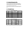
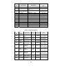
10.1 BACnet MS/TP Server
Table 1: List of Binary Outputs
Instance
ID
BO0
BO1
BO2
BO3
BO4
BO5
BO6
BO7
BO8
Object Name
Run/Stop Cmd
Rev/Fwd Cmd
External Fault
Fault Reset
PRG->DRV Mode
DRV->PRG Mode
Relay Output
Digital Output 1
Digital Output 2
Description
Active/Inactive Text
Run/Stop Command
Reverse/Forward Command
External Fault
Fault Reset
Switch to DRV mode from PRG
Switch to PRG mode from DRV
Relay Output Command
Digital Output 1 Command
Digital Output 2 Command
Run/Stop
Reverse/Forward
Set/Clear
Set/Clear
PRG->DRV/Invalid
DRV->PRG/Invalid
Set/Clear
Set/Clear
Set/Clear
Table 2: List of Analog Outputs
Instance
ID
AO0
AO1
AO2
Object Name
Description
Host Link
Frequency
Reference
Analog Output 1
Analog Output 1
Command
Analog Output 2
Analog Output 2
Command
H.L. Freq Ref
24
Units Multiplier
Notes
Multiplier must
Hertz
0.002000 change if Cn-02 is
(27)
not set to 60.0 Hz
Volts
0.010000
(5)
Volts
0.010000
(5)
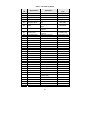
Table 3: List of Binary Inputs
Instance
ID
Object Name
BI0
BI1
BI2
BI3
Run/Stop Stat
Zero Speed
Rev/Fwd Stat
Inverter Ready
BI4
DRV/PRG Mode
BI5
Series
BI6
Inverter Alarm
BI7
Inverter Fault
BI8
BI9
BI10
BI11
BI12
BI13
BI14
BI15
BI16
BI17
BI18
BI19
BI20
BI21
BI22
BI23
BI24
BI25
BI26
BI27
BI28
LCD Digital Oper
UV1 Fault
OC Fault
OV Fault
OH Fault
OL1 Fault
OL2 Fault
OL3 Fault
EF3 Fault
EF5 Fault
EF6 Fault
EF7 Fault
EF8 Fault
CPF04 Fault
CPF05 Fault
GF Fault
PG Over Spd Flt
UV Alarm
OV Alarm
OH Alarm
OL3 Alarm
BI29
EF Alarm
BI30
BI31
BI32
BI33
BI34
BB Alarm
EEPROM Alarm
EF3 Alarm
PG Over Spd Alm
PG Spd Dev Alarm
Description
Active/Inactive
Text
Run/Stop Status
Running/Stopped
Indicates drive’s speed is 0
Zero/Non-Zero
Reverse/Forward Status
Reverse/Forward
Inverter Ready
Ready/Unready
The current mode of the
DRV/PRG
drive
The drive is 440V or 220V
440V/220V
series
Indicates an alarm has been
Alarm/No Alarm
triggered
Indicates a fault has been
Fault/No Fault
triggered
LCD Digital Operator
Present/Not Pres
Under Voltage Fault
Fault/No Fault
Over Current Fault
Fault/No Fault
Over Voltage Fault
Fault/No Fault
Over Heat Fault
Fault/No Fault
Motor Over Load Fault
Fault/No Fault
Inverter Over Load Fault
Fault/No Fault
Output Over Torque Fault
Fault/No Fault
External Fault 3
Fault/No Fault
External Fault 5
Fault/No Fault
External Fault 6
Fault/No Fault
External Fault 7
Fault/No Fault
External Fault 8
Fault/No Fault
EEPROM Fault
Fault/No Fault
CPU A/D Fault
Fault/No Fault
Ground Fault
Fault/No Fault
PG Over Speed Fault
Alarm/No Alarm
Under Voltage Alarm
Alarm/No Alarm
Over Voltage Alarm
Alarm/No Alarm
Over Heat Alarm
Alarm/No Alarm
Over Torque Alarm
Alarm/No Alarm
Two Line Terminal 1, 2
Alarm/No Alarm
External Alarm
Base Block Alarm
Alarm/No Alarm
EEPROM Alarm
Alarm/No Alarm
External Alarm 3
Alarm/No Alarm
PG Over Speed Alarm
Alarm/No Alarm
PG Speed Deviation Alarm
Alarm/No Alarm
25
Instance
ID
BI35
BI36
BI37
BI38
BI39
BI40
BI41
BI42
BI43
BI44
BI45
BI46
BI47
BI48
Object Name
Description
PG Line Alarm
PG Line Alarm
Braking Resistor Over Heat
Brake Res Alarm
Alarm
RS-485 Communication
RS-485 Com Alarm
Alarm
DI 1 Status
Digital Input 1 Status
DI 2 Status
Digital Input 2 Status
DI 3 Status
Digital Input 3 Status
DI 4 Status
Digital Input 4 Status
DI 5 Status
Digital Input 5 Status
DI 6 Status
Digital Input 6 Status
DI 7 Status
Digital Input 7 Status
DI 8 Status
Digital Input 8 Status
RA-RB-RC Status
Relay Output Status
DO1-DOG Status
Digital Output 1 Status
DO2-DOG Status
Digital Output 2 Status
Active/Inactive
Text
Alarm/No Alarm
Alarm/No Alarm
Alarm/No Alarm
Close/Open
Close/Open
Close/Open
Close/Open
Close/Open
Close/Open
Close/Open
Close/Open
Close/Open
Close/Open
Close/Open
Table 4: List of Analog Inputs
Instance
ID
Object
Name
Description
Monitor Data
Word
Word containing
fault causes
Word containing
alarm causes
Word containing
alarm causes
Units
No Units
(95)
No Units
(95)
No Units
(95)
No Units
(95)
Multiplier
AI0
Status
Word
AI1
Faults
AI2
Alarms 1
AI3
Alarms 2
AI4
Frequency Frequency
Ref
Reference
Hertz
(27)
0.002000
AI5
Output
Output
Frequency Frequency
Hertz
(27)
0.002000
AI6
PG Speed PG Speed
FB
Feedback
Hertz
(27)
0.060000
AI7
Output
Current
AI8
DC Voltage DC Voltage
Amps
(3)
Volts
(5)
Output Current
26
1.000000
1.000000
1.000000
1.000000
0.100000
1.000000
Notes
Modbus register
address 0020H
Modbus register
address 0021H
Modbus register
address 0022H
Modbus register
address 0023H
Multiplier must
change if Cn-02 is
not set to 60.0 Hz
Multiplier must
change if Cn-02 is
not set to 60.0 Hz
Multiplier must
change if Cn-02 is
not set to 60.0 Hz
Instance
ID
AI9
AI10
AI11
AI12
AI13
AI14
AI15
Object
Name
Description
Units
Analog
Input VIN
Analog
Input AIN
Analog
Input AUX
Multiplier
Analog Input VIN
Volts
0.010000
Value
(5)
Analog Input AIN Milliamps
0.020000
Value
(2)
Analog Input
Volts
0.010000
AUX Value
(5)
Word containing
No Units
Digital
Digital Input
1.000000
(95)
Inputs
Status 1-8
Analog Output 1
Volts
AO1 Value
0.010000
Value
(5)
Analog Output 2
Volts
AO2 Value
0.010000
Value
(5)
Word containing
No Units
Digital
Relay and Digital
1.000000
(95)
Outputs
Output Status
27
Notes
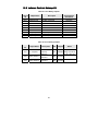
10.2 Johnson Controls Metasys N2
Table 5: List of Binary Outputs
Instance
ID
BO1
BO2
BO3
BO4
BO5
BO6
BO7
BO8
BO9
Object Name
Run/Stop Cmd
Rev/Fwd Cmd
External Fault
Fault Reset
PRG->DRV Mode
DRV->PRG Mode
Relay Output
Digital Output 1
Digital Output 2
Description
Active/Inactive
Description
Run/Stop Command
Reverse/Forward Command
External Fault
Fault Reset
Switch to DRV mode from PRG
Switch to PRG mode from DRV
Relay Output Command
Digital Output 1 Command
Digital Output 2 Command
Run/Stop
Reverse/Forward
Set/Clear
Set/Clear
PRG->DRV/Invalid
DRV->PRG/Invalid
Set/Clear
Set/Clear
Set/Clear
Table 6: List of Analog Outputs
Instance
ID
AO1
AO2
AO3
Object Name
Description
Host Link
Frequency
Reference
Analog Output 1
Analog Output 1
Command
Analog Output 2
Analog Output 2
Command
H.L. Freq Ref
28
Units Multiplier
Notes
Multiplier must
Hertz 0.002000 change if Cn-02 is
not set to 60.0 Hz
Volts 0.010000
Volts 0.010000
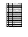
Table 7: List of Binary Inputs
Instance
ID
Object Name
BI1
BI2
BI3
BI4
Run/Stop Stat
Zero Speed
Rev/Fwd Stat
Inverter Ready
BI5
DRV/PRG Mode
BI6
Series
BI7
Inverter Alarm
BI8
Inverter Fault
BI9
BI10
BI11
BI12
BI13
BI14
BI15
BI16
BI17
BI18
BI19
BI20
BI21
BI22
BI23
BI24
BI25
BI26
BI27
BI28
BI29
LCD Digital Oper
UV1 Fault
OC Fault
OV Fault
OH Fault
OL1 Fault
OL2 Fault
OL3 Fault
EF3 Fault
EF5 Fault
EF6 Fault
EF7 Fault
EF8 Fault
CPF04 Fault
CPF05 Fault
GF Fault
PG Over Spd Flt
UV Alarm
OV Alarm
OH Alarm
OL3 Alarm
BI30
EF Alarm
BI31
BI32
BI33
BI34
BI35
BB Alarm
EEPROM Alarm
EF3 Alarm
PG Over Spd Alm
PG Spd Dev Alarm
Description
Active/Inactive
Description
Run/Stop Status
Running/Stopped
Indicates drive’s speed is 0
Zero/Non-Zero
Reverse/Forward Status
Reverse/Forward
Inverter Ready
Ready/Unready
The current mode of the
DRV/PRG
drive
The drive is 440V or 220V
440V/220V
series
Indicates an alarm has been
Alarm/No Alarm
triggered
Indicates a fault has been
Fault/No Fault
triggered
LCD Digital Operator
Present/Not Pres
Under Voltage Fault
Fault/No Fault
Over Current Fault
Fault/No Fault
Over Voltage Fault
Fault/No Fault
Over Heat Fault
Fault/No Fault
Motor Over Load Fault
Fault/No Fault
Inverter Over Load Fault
Fault/No Fault
Output Over Torque Fault
Fault/No Fault
External Fault 3
Fault/No Fault
External Fault 5
Fault/No Fault
External Fault 6
Fault/No Fault
External Fault 7
Fault/No Fault
External Fault 8
Fault/No Fault
EEPROM Fault
Fault/No Fault
CPU A/D Fault
Fault/No Fault
Ground Fault
Fault/No Fault
PG Over Speed Fault
Alarm/No Alarm
Under Voltage Alarm
Alarm/No Alarm
Over Voltage Alarm
Alarm/No Alarm
Over Heat Alarm
Alarm/No Alarm
Over Torque Alarm
Alarm/No Alarm
Two Line Terminal 1, 2
Alarm/No Alarm
External Alarm
Base Block Alarm
Alarm/No Alarm
EEPROM Alarm
Alarm/No Alarm
External Alarm 3
Alarm/No Alarm
PG Over Speed Alarm
Alarm/No Alarm
PG Speed Deviation Alarm
Alarm/No Alarm
29
Instance
ID
BI36
BI37
BI38
BI39
BI40
BI41
BI42
BI43
BI44
BI45
BI46
BI47
BI48
BI49
Object Name
Description
PG Line Alarm
PG Line Alarm
Braking Resistor Over Heat
Brake Res Alarm
Alarm
RS-485 Communication
RS-485 Com Alarm
Alarm
DI 1 Status
Digital Input 1 Status
DI 2 Status
Digital Input 2 Status
DI 3 Status
Digital Input 3 Status
DI 4 Status
Digital Input 4 Status
DI 5 Status
Digital Input 5 Status
DI 6 Status
Digital Input 6 Status
DI 7 Status
Digital Input 7 Status
DI 8 Status
Digital Input 8 Status
RA-RB-RC Status
Relay Output Status
DO1-DOG Status
Digital Output 1 Status
DO2-DOG Status
Digital Output 2 Status
Active/Inactive
Description
Alarm/No Alarm
Alarm/No Alarm
Alarm/No Alarm
Close/Open
Close/Open
Close/Open
Close/Open
Close/Open
Close/Open
Close/Open
Close/Open
Close/Open
Close/Open
Close/Open
Table 8: List of Analog Inputs
Instance
ID
Object
Name
Description
Units
AI1
Status
Word
AI2
Faults
AI3
Alarms 1
AI4
Alarms 2
AI5
Frequency Frequency
Ref
Reference
Hertz
0.002000
AI6
Output
Output
Frequency Frequency
Hertz
0.002000
AI7
PG Speed PG Speed
FB
Feedback
Hertz
0.060000
Amps
0.100000
Volt
1.000000
AI8
AI9
Monitor Data
Word
Word containing
fault causes
Word containing
alarm causes
Word containing
alarm causes
Multiplier
1.000000
1.000000
1.000000
1.000000
Output
Output Current
Current
DC Voltage DC Voltage
30
Notes
Modbus register
address 0020H
Modbus register
address 0021H
Modbus register
address 0022H
Modbus register
address 0023H
Multiplier must
change if Cn-02 is
not set to 60.0 Hz
Multiplier must
change if Cn-02 is
not set to 60.0 Hz
Multiplier must
change if Cn-02 is
not set to 60.0 Hz
Instance
ID
AI10
AI11
AI12
AI13
AI14
AI15
AI16
Object
Name
Description
Units
Analog
Input VIN
Analog
Input AIN
Analog
Input AUX
Multiplier
Analog Input VIN
Volts
0.010000
Value
Analog Input AIN
Milliamps 0.020000
Value
Analog Input
Volts
0.010000
AUX Value
Word containing
Digital
Digital Input
1.000000
Inputs
Status 1-8
Analog Output 1
AO1 Value
Volts
0.010000
Value
Analog Output 2
AO2 Value
Volts
0.010000
Value
Word containing
Digital
Relay and Digital
1.000000
Outputs
Output Status
31
Notes
ICC
INDUSTRIAL CONTROL COMMUNICATIONS, INC.
1600 Aspen Commons, Suite 210
Middleton, WI USA 53562-4720
Tel: [608] 831-1255 Fax: [608] 831-2045
http://www.iccdesigns.com
Printed in U.S.A