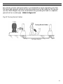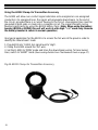
1
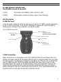
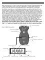
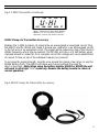
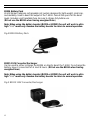
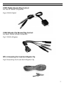
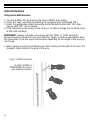
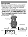
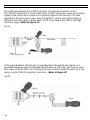
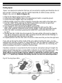
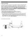
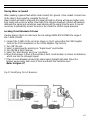
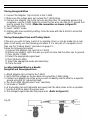
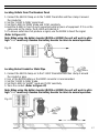
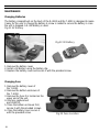
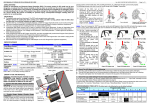
AT-4000
Advanced Tracer
User’s Manual
Amprobe thanks you for purchasing the AT-4000 Advanced Tracer. For your safety, please read
this instruction manual in its entirety.
LIMITED WARRANTY
VÉÇzÜtàâÄtà|ÉÇá4
Your new instrument has been
quality crafted according to quality standards and contains
quality components and workmanship. It has been inspected for proper operation of all of its functions and tested by
qualified factory technicians according to the longestablished standards of our company.
Your instrument has a limited warranty against defective
materials and/or workmanship for one year from the date of
purchase provided that, in the opinion of the factory, the
instrument has not been tampered with or taken apart.
Should your instrument fail due to defective materials,
and/or workmanship during this one year period, a no charge
repair or replacement will be made to the original purchaser. Please have your dated bill of sale, which must identify
the instrument model number and serial number and call the
number listed below:
Repair Department
Phone:954-499-5400 / 800-327-5060
Fax:954-499-5454
Website:www.Amprobe.com
Please obtain an RMA number before
returning product for repair.
Outside the U.S.A. the local representative will assist you.
Above limited warranty covers repair and replacement of
instrument only and no other obligation is stated or implied.
Table of Contents
Precautions & Introduction...........................................................................................02
Product Description.....................................................................................................03
Application Notes.........................................................................................................08
Using the R-4000........................................................................................................ 08
Using the T-4000.........................................................................................................09
A2202 Clamp-on Transmitter Accessory...................................................................... 12
Finding Opens.............................................................................................................13
Finding Ground Faults..................................................................................................14
Tracing Wires in Conduit..............................................................................................15
Locating Circuit Breakers or Fuses..............................................................................15
Tracing Wires...............................................................................................................16
Maintenance................................................................................................................18
Replacement Parts...................................................................................................... 19
Troubleshooting........................................................................................................... 19
Specifications..............................................................................................................20
PRECAUTIONS
FOR PERSONAL AND INSTRUMENT PROTECTION
IMPORTANT:
1. Before using any electrical instrument, it should be checked to make certain it is
operating properly.
2. In many instances, you will be working with dangerous levels of voltages and/or current,
therefore, it is important that you avoid direct contact with any uninsulated, current
carrying surfaces. Appropriate insulated gloves and protective clothing should be worn.
3. Before attaching any of the conductors, make sure the voltage present is not beyond
the range of the instrument.
4. When not in use, keep the instruments in their carrying case.
5. When the R-4000 or the T-4000 will not be used for a period of time, remove the
battery to prevent leakage in the instrument.
INTRODUCTION
AMPROBE ATP SPX is dedicated to designing, manufacturing and marketing high quality,
reliable instruments for the skilled professional. The AMPROBE ATP SPX current tracer has
a history of providing safe, reliable operation in tracing energized wires, locating circuit
breakers and locating wires shorted to the ground. The AMPROBE ATP SPX open tracer has
the capability of tracing unenergized wires, locating open breakers and locating
open wires.
The AT-4000 Wire Tracer Upgrade System combines both the current tracing CT-100
and the AT-2000 series into one versatile tool providing the ability to solve virtually all
your tracing problems. In addition to the above features, the receiver provides a non
position sensitive when tracing wire and the transmitter provides a visual indication to
the user when the traced line is energized. The level of the signal transmission is also
indicated on the LCD of the transmitter unit.
Having confidence in an instrument is an important part of using the instrument. All
applications are different and unique. An understanding of the system’s operation
could mean the difference between several minutes or several hours on the job.
Please read this manual carefully. Take the time to learn how the instrument operates. The
operation is user friendly and easy to learn. Test it in a variety of situations. You will soon
have the confidence to use it on a daily basis to solve problems that were
previously unsolvable.
2
AT-4000 PRODUCT DESCRIPTION
The AT-4000 consists of two units:
T-4000
Transmitter (32.768KHZ, 9-600 volts AC or DC)
R-4000
Receiver(Non-position sensitive, Open / Short Tracing)
Unit Description
R-4000 Receiver:
It has two built in detectors that are tuned to pick up the 32.768Khz signals generated
by the T-4000 transmitter. The R-4000 is designed to display the signal strength to
enable quick locating of the conductor carrying the signal.
Fig.1 R-4000 Receiver
LED Indicator:
ON-OPEN
OFF-SHORT
LED Indicator:
ON-High Sensitivity
BLINKING - Medium Sensitivity
OFF-Low Sensitivity for breakers
Sensitivity Control
Mode Control
Power ON/OFF
LED Indicator:
Green-Unit ON
Red-Low Battery
T-4000 Transmitter
When connected to an energized circuit, the T-4000 will filter the low frequencies up to
400Hz and rapidly indicate on the display that the wire is energized. When the user starts
the transmission, a combination of signals is injected on top of the 50, 60, or 400Hz that
cause a slight, periodic current fluctuation and allows the power line to emit its own,
traceable signal. This signal can be detected back to the main generator. However, the
signal will not interfere with any sensitive electronic equipment and does not require
power interruption. The unit is intrinsically safe and has a ‘LOW’ signal transmission setting that must be used when tracing GFCI-protected circuits.
3
When connecting to a circuit as a load, the signal will be present anywhere between the
T-4000 and the power source. (Line side or Upstream)- no signal will be present on
wiring on the other side of the transmitter(load side or downstream). For example, a
transmitter connected to a circuit breaker will produce no signal on that circuit. It will,
however, cause a signal to be generated between that panel and the transformer…and
beyond. When connecting to an unenergized circuit, the live indication on the display will
remain ‘OFF’. When the user starts the transmission, the transmitter injects a combination of signals onto the conductor. The signal will travel along the conductor until it ends.
There is no difference in the functional mode of the unit when tracing energized circuit
and unenergized circuits. On an open line, no current will flow, so the injected signal will
present itself as a voltage spike along the wire which is detected by the R-4000 in the
‘OPEN’ mode. When the conductor is part of a complete circuit, the voltage causes a
current to flow which produces a signal that is detected in the ‘SHORT’ mode. The
T-4000 contains a 9V battery. A 24V input jack accepts the B2024 rechargeable battery
or the B2025 110V converter, both use when a very strong signal is necessary.
(Note: When using the battery booster (B2024 or B2025) the unit will work in ultra
high “U-HI” mode only. Remove the battery booster to return to normal operation.)
Banana Plug Jack
Fuse (inside) Holder
Fig.2 T-4000 Transmitter
Signal Level Switch
Power ON/OFF
24 Volt Jack
9V Battery Compartment
SET (select a signal level)
(Energized Line) Live
Low Battery
q
LIVE
SET
VOP
18888
OFF
Transmission OFF
4
LOW
MID
Transmission LOW
HIGH
M
LCD Display
FT
Transmission MEDIUM Transmission HIGH
Fig.2 T-4000 Transmitter Continued
q
OFF
LIVE
SET
VOP
U-Hi
LOW
MID
HIGH
M
FT
“U-HI” - Transmission Ultra High: Battery
booster is in use. To return to normal
operation, remove the battery booster.
A2202 Clamp-On Transmitter Accessory
Enables the T-4000 to induce its signal onto an unenergized or energized circuit. Plug
the A2202 into the T4000 and clamp it around any conductor in an unenergized circuit,
or the hot wire in an energized circuit. The signal will be induced on top of the 50,60,or
400Hz frequency which may be present. The AT2201 acts like a 1/2 Volt battery when
clamped around a conductor. On a complete circuit this voltage will cause about 80mA
of current to flow on top of the whatever frequency is present.
To increase the signal strength, loop the wire around the clamp a few times or use the
B2024 battery Pack. The A2202 will allow wire tracing without the need for
direct connection. (Note: When using the battery booster (B2024 or B2025) the unit
will work in ultra high “U-HI” mode only. Remove the battery booster to return to
normal operation.)
Fig.3 A2202 Clamp-On Transmitter Accessory
5
B2024 Battery Pack
24 Volt Nickel-Cadmium rechargeable cell custom designed for light weight, small size,
and durability. Used to boost the output of the T-4000. Consult the specs for the boost
levels. Includes a self-resetable fuse. Be sure to charge fully before use.
(DO not use the B2024 when tracing energized lines.)
Note: When using the battery booster (B2024 or B2025) the unit will work in ultra
high “U-HI” mode only. Remove the battery booster to return to normal operation.
Fig.4 B2024 Battery Pack
B2025 110V Converter/Recharger
Can be used to either recharge the B2024 or directly boost the T-4000. To recharge the
battery, leave it connected for at least 8 hours. (DO not use the B2024 when tracing
energized lines.)
Note: When using the battery booster (B2024 or B2025) the unit will work in ultra
high “U-HI” mode only. Remove the battery booster to return to normal operation.
Fig.5 B2025 110V Converter/Recharger
6
C2901 Pigtail- Banana Plug Cord set
For use on 110VAC receptacles.
Fig.6 C2901 Pigtail
C2902 Alligator-Clip Banana Plug Cord set
For direct contact to bare conductors
Fig.7 C2902 Alligator
MTL-G Grounding Test lead And Alligator Clip
Fig.8 Grounding Test Lead And Alligator Clip
7
APPLICATION NOTES
Using the R-4000 Receiver
1. Turn the R-4000 ‘ON’ by pressing the Power ON/OFF push button.
2. Select the ‘High’ sensitivity by pressing the sensitivity push button(LED ‘ON’).
3. Select the appropriate mode by pressing the MODE push button (LED ‘ON’: Open
tracing; LED ‘OFF’: Short tracing)
4. If the indication on the display is too strong (7-10 LEDs), change the sensitivity level
to MID (LED ‘blinking’).
IMPORTANT: Always conclude your tracing with the “MID” or “LOW” sensitivity
because the built in detector has a 360˚ detection range. It will be a good idea to have
the transmitter on the low signal transmission depending on the length of the wire you
are tracing.
5. When tracing, move the R-4000 back and forth slowly over the path of the wire. The
strongest signal confirms the path of the wire.
Fig.9 R-4000 Receiver
In either SHORT or
OPEN MODE, the unit is
non position sensitive
8
Using the T-4000 Transmitter
1. Make sure the voltage is not higher than 600V on the conductor you wish to trace.
2. Always connect the banana plugs to the T-4000 before connecting to the circuit.
3. Using the alligator clip cord set, connect the banana plugs to the transmitter.
4. Connect one alligator clip to the wire you wish to trace(it doesn’t matter which one
as the input plugs are not polarized) and the other one to a separate ground.
5. Turn the unit ‘ON’ by pressing on the ON/OFF push button- The screen should
display ‘18888’ briefly. The transmission is ‘OFF’
6. Select the signal transmission level (LOW, MID, HIGH) by pressing on the signal level
push button. It takes about 2 seconds for the transmission to start after you last hit
the push button. (Note: When using the battery booster (B2024 or B2025) the unit
will work in ultra high “U-HI” mode only. Remove the battery booster to return to
normal operation.)
7. Trace the wire with the R-4000 receiver. The signal will stop at the break in the wire.
IMPORTANT: When using the T-4000 in energized circuits with GFCI protection,
always use the Low level transmission.
Fig.10 T-4000 Transmitter
Banana Plug Jack
Fuse (inside) Holder
Signal Level Switch
Power ON/OFF
24 Volt Jack
9V Battery Compartment
q
SET (select a signal level)
(Energized Line) Live
OFF
Low Battery
q
LIVE
SET
VOP
18888
OFF
Transmission OFF
LOW
MID
Transmission LOW
HIGH
LIVE
SET
VOP
U-Hi
LOW
MID
HIGH
M
FT
“U-HI”: Transmission Ultra High. Battery
booster is in use. To return to normal
operation, remove the battery booster.
M
LCD Display
FT
Transmission MEDIUM Transmission HIGH
9
The signal generated by the T-4000 is present at all points around the circuit.
The T-4000 connected to a 110V outlet via the C2901 cord set will cause an incoming
signal on the neutral wire as well as an outgoing signal on the hot wire. The close
proximity of these two wires may cause the signals to cancel each other, making it
difficult to trace the cable in these areas. In this case, keep the R-4000 in the high
sensitivity range. (Refer to Figure 11)
Fig.11
R-4000
T-4000
At the panel breakers, the hot wire is separated from the neutral wire (where it is
grounded) allowing easy circuit breaker identification. In that case, use the Low sensitivity range of the R-4000. So, if tracing the branch wiring through the walls is not necessary, use the C2901 for quicker connection. (Refer to Figure 12)
Fig.12
R-4000
T-4000
10
Easy tracing of wires and buried cable is accomplished by simply separating wire from
the return path (ground). Instead of using the neutral wire or the conduit as the ground,
use the C2902 Alligator Clip cord set and attach the grounding test lead to a separate
ground such as a water pipe. (Refer to Figure 13)
Fig.13 Tracing Buried Cables
T-4000
11
Using the A2202 Clamp-On Transmitter Accessory
The A2202 will allow non-contact signal indication onto energized or non-energized
conductors. On energized lines, the signal will propagate downstream to the end of
the circuit, provided there is a current flowing in the circuit. Unenergized lines must be
grounded at both ends or made into a complete circuit. The signal strength can be
boosted significantly by using the B2024 battery Pack. (Note: When using the battery
booster (B2024 or B2025) the unit will work in ultra high “U-HI” mode only. Remove
the battery booster to return to normal operation.)
One typical application for the A2202 is to access the hot wire at the panel in order to
identify the ‘downstream’ loads:
1. Plug A2202 into T-4000. Set signal level to ‘High’.
2. Clamp the A2202 around the ‘hot’ wire.
3. Set the R-4000 to ‘OPEN’ mode and trace the downstream wiring. To trace buried
lines, switch to ‘SHORT’ mode (See Locating Outlets From The Breakers Panel on page 17)
Fig.14 A2202 Clamp-On Transmitter Accessory
12
Finding Opens
‘Opens’ are dead-end conductors that are not connected to anything and therefore do not
pass current. To find an Open, use the T-4000 transmitter, R-4000 receiver, and the
alligator clip cord set. (Refer to figure 15)
1. Plug the two banana plugs into the T-4000
2. Connect one of the alligator clips or the grounding test lead to a separate ground.
3. Connect the other alligator clip to the conductor.
4. Where possible, ground any other conductors sharing the same path as the Open wire.
5. Turn the T-4000 ‘ON’ by pressing the ON/OFF push button and select a signal level
transmission by pressing the signal level push button.
6. Turn the R-4000 ‘ON’ by pressing the ON/OFF push button.
7. Select ‘OPEN’ mode by pressing the MODE push button( the LED must be ‘ON’).
Note: If the conductor is buried in moist soil, the ‘SHORT’ mode may give better results.
8. Select the ‘HIGH’ sensitivity by pressing the SENSITIVITY push button (the LED must
be ‘ON’).
9. Starting from the T-4000, trace the conductor. The open will be at the point you begin to
lose signal. At that point, select the ‘MID’ sensitivity mode (the LED must be ‘blinking’) in
order to pinpoint the exact location of the Open.
10. Repeat process from the other end of the wire to make sure that you trace the right wire.
If you end up tracing the entire length of the wire without locating the open, you may
experiencing capacitive coupling, or ‘Signal bleed-off’ onto the adjacent conductors. This
condition may be alleviated by: a) grounding all adjacent conductors; b) minimizing the
distance between the point of connection and the open.
If another conductor is connected to the first conductor somewhere along its length, the
signal will split between them, causing both conductors to emit half the signal each. The
B2024 battery or the B2025 converter can be used to increase the signal strength.
(Note: When using the battery booster (B2024 or B2025) the unit will work in ultra
high “U-HI” mode only. Remove the battery booster to return to normal operation.)
Fig.15 Tracing Open Wire
R-4000
T-4000
13
Finding Ground Faults
A ground fault is a direct connection of the conductor to ground. A typical ground fault
may cause a tripped circuit breaker or a blown fuse ( in contrast to an ‘open’, which
passes no current). In this situation, the B2024 battery can be used as the current
source. The high voltage from the B2024 will overcome a high resistance fault and will
produce a stronger signal. Also, you can use line voltage as the power source by
connecting the T-4000 across the breaker. (Note: When using the battery booster
(B2024 or B2025) the unit will work in ultra high “U-HI” mode only. Remove the battery booster to return to normal operation.)
1. Plug the alligator clip cord set into the T-4000.
2. Attach one clip to the faulted wire and the other one to ground.
3. Press the signal level push button and select the appropriate level.
4. If possible, ground all adjacent conductors.
5. The R-4000 receiver can then be used to trace the wire. The signal should remain
relatively constant until you pass the ground fault. At the fault, the signal from the
T-4000 will pass from the wire and disperse into the ground. For this reason, the
signal strength will decrease gradually. Watch the LEDs carefully in order to locate
the fault within a few inches. (Refer to Figure16)
Fig.16 Finding Ground Faults
B2024
T-4000
14
Tracing Wires in Conduit
When seeking a ground fault within metal conduit, the ‘ground’ is the conduit. Connect one
of the clips to the conduit to complete the circuit.
Steel conduit will tend to attenuate the signal strength so tracing will require higher sensitivity levels and access to within a few feet of the conduit. Aluminum conduit will severely
attenuate the signal and sometimes even blocking all the signal from the wire. It may be
necessary to periodically access the wire in the conduit to confirm signal presence.
Locating Circuit Breakers Or Fuses
Caution: Always check to make sure the line voltage DOES NOT EXCEED the range of
the T-4000: 9-600V
1. Connect the T-4000 to the circuit as shown in Fig.17 using either the C2901 pigtail
Cord set for 110V receptacles or the C2902 Alligator Clip cord set.
2. Turn ‘ON’ the unit.
3. Select a signal level by pressing on “Signal Level” push button.
4. Turn ON the R-4000 receiver.
5. Select the ‘Short Range’ and ‘Low’ sensitivity.
6. Move the Receiver in front of the outside of each circuit breaker, as shown, to determine
which one has the strongest signal.
7. If two or more breakers produce the same signal strength indication. Move the
receiver away slowly from each of them and watch the indication level.
(Refer to Figure 17)
Fig.17 Identifying Circuit Breakers
R-4000
T-4000
T-4000
15
Tracing Energized Wires
1. Connect the Alligator Clip Cord set to the T-4000.
2. Make sure the voltage does not exceed the T-4000 rating.
3. Connect one alligator clip to the hot wire and the other to a separate ground. At a
receptacle, use the C2901 Pigtail to access the hot wire. Use the 25-FT ground test
lead to ground the T-4000. (Make the connection as shown in Figure11)
4. Turn ON the R-4000.
5. Select ‘SHORT’ mode.
6. Starting with Low sensitivity setting, circle the area with the R-4000 to locate the
path of the wire.
Tracing Unenergized Lines and Finding Shorts
If the wire you wish to trace is part of a complete circuit, or can be made into a complete circuit easily, use the following procedure. If it is not part of a complete circuit
then use the “Finding Opens” procedure on page 13.
Follow the following procedure:
A) Connect the alligator clip cord set to T-4000.
B) Attach one alligator clip to the wire you wish to trace and the other one to ground.
C) Turn ON the T-4000.
D) Select the appropriate signal level.
E) Turn ON the R-4000.
F) Select the appropriate mode and sensitivity.
G) Trace the wire.
Locating Individual Wires in a Bundle
Energized and Unenergized Lines
1. Attach alligator clip cord set to the T-4000.
2. Verify that the voltage on the line does not exceed the T-4000 rating.
3. Connect one alligator clip to the wire you wish to identify and the other to a separate
ground using the 25’ ground test lead.
4. Turn the R-4000 ON and select ‘Low” sensitivity.
5. Set mode to “SHORT”.
6. At the bundle, pull each individual wire away from the other wires as far as possible.
7. Use the R-4000 to detect the proper wire.
8. The strongest signal indicates the proper wire (Refer to Figure 18)
Fig.18
R-4000
T-4000
16
Locating Outlets From The Breakers Panel
1. Connect the A2202 Clamp-on to the T-4000 Transmitter and then clamp it around
the conductor.
2. Set the T-4000 to ‘HIGH’ signal level.
3. Set the R-4000 to ‘OPEN’ mode and ‘LOW’ sensitivity.
4. Hold the R-4000 in front of each suspected outlet or piece of equipment. If it is on the
same wire as the clamp, the R-4000 will indicate it.
5. If a known outlet does not produce a signal, use the B2024 to boost the signal.
(Refer to Figure 19)
Note: When using the battery booster (B2024 or B2025) the unit will work in ultra
high “U-HI” mode only. Remove the battery booster to return to normal operation.
Fig.19
T-4000
Locating Buried Conduit or Metal Pipe
B2024
1. Connect the A2202 clamp-on to the T-4000 Transmitter and then clamp it around
the conduit or pipe.
2. Use of the B2024 battery or the B2025 converter is recommended.
3. Set the T-4000 to ‘HIGH’ mode.
4. Set the R-4000 to ‘SHORT’ mode and ‘LOW’ sensitivity.
5. Trace the conduit. (Refer to Figure 20)
Note: When using the battery booster (B2024 or B2025) the unit will work in ultra
high “U-HI” mode only. Remove the battery booster to return to normal operation.
Fig. 20
R-4000
T-4000
B2024
17
MAINTENANCE
Changing Batteries
The battery compartment on the back of the R-4000 and the T-4000 is designed to make
it easy for the user to change the battery. A screw is added to secure the battery in case
the unit is dropped. A 9-Volt battery is used.
Fig.21 9V Battery
Fig.22 9V Battery
1. Remove the battery cover.
2. Install a 9V Battery using the battery clip.
3. Replace the battery cover and secure it with the provided screw.
Changing Fuse
1. Remove the battery cover of
the T-4000.
2. Remove the bottom enclosure of
the T-4000.
3. Remove the fuse. It is located on the
upper end of the unit.
4. Use fuse replacement
part #100721.
5. Close the bottom enclosure first,
secure it with the provided screws.
6. Close the battery cover, secure it
with the provided screw.
18
Fig.23 Fuse Location
REPLACEMENT PARTS
9V Battery.................................................................................................9V Alkaline
Clamp-On Transmitter Accessory..............................................................A2202
Battery Pack..............................................................................................B2024
10V Converter/Recharger...........................................................................B2025
110V Pigtail - Banana Plug Cord Set.........................................................C2901
Alligator - Clip Banana Plug Cord Set........................................................C2902
Grounding Test Lead 25-FT.......................................................................MTL-G
Alligator Clip..............................................................................................VRC-320
Carrying Case AT-4000.............................................................................CC-AT-4000
Owners Manual........................................................................................www.Amprobe.com
Fuse 1000V 0.25A FA 6X46MM................................................................FA6X46MM
TROUBLE SHOOTING
Symptom
Possible Cause
Solution
LCD Segments of the
T-4000 are fading
9V battery is low in voltage
Replace the battery
R-4000 Can’t detect signal
a) Wrong Mode or Range
a) Ensure that you are using
the right mode or range.
(See application notes)
b) Transmitter is OFF or the
signal level is too low
c) Signal Cancellation
b) Turn ON the transmitter
and select the appropriate
signal level.
c) Use a separate ground or
separate the wires.
19
SPECIFICATIONS
General
Operating Temperature: 0 to 120˚ F (-18˚C to 49˚C)
Storage temperature: -40˚ to 150˚ F (-40˚ to 66˚C)
Case Material: ABS
Case Size: 0.55” x 0.26” (14x6.7mm)
R-4000 Receiver
Detectors: Electromagnetic Coil Array pick up for short mode.
Electrostatic plate pick up for open mode.
Sensitivity: Low and High programmable gain from the traced wire.
Short Mode performance: Over 20’ in air from the traced wire under
test conditions.
Open Mode performance: Over 12’ from the traced wire in air under
test conditions.
50HZ, 60HZ, and 400HZ Rejection: 120db
Power Source: 9V alkaline battery
Display: 10 LEDs
Case: Flame retardant ABS
Weight: 0.5 Lb. (113g)
T-4000 Transmitter
Operating voltage: 9-600 volts
Operating frequency: 32.768 KHZ
Duty Cycle: Transmit 2 pulses with a duration of 0.0625S
each, every 0.5 seconds
Case: Flame retardant ABS
Display: LCD (Liquid Crystal Display)
Weight: 0.32 LB (143.5g)
20
Current Output of the Signal:
Low Mode: 11 mA average, 30 mA peak
Medium Mode: 12 mA average, 36 mA peak
High Mode: 13 mA average, 63 mA peak
Fuse: Fast acting 250 mA @ 1000V (6X46mm) P/N: FA6X46MM
Signal Output (9V supply):
High setting: 0.74 VAC
Medium setting: 0.61 VAC
Low setting: 0.53 VAC
Battery: 9V alkaline- 24V jack will accept battery pack accessory
(B2024 or B2025)
A2202 Clamp-on Transmitter Accessory
Operating Frequency: 32.768KHZ as supplied by T-4000
Case Breakdown Voltage: 3000 volts
Maximum Wire size: 2000 MCM or 2” dia. Cable
Battery: None, power is supplied by T-4000
B2024 Battery Pack
Type: Nickel-Cadmium rechargeable (20 AA cells)
Capacity: 24-Volt, 600 mah
Rechargeable Time: 14 hours
Fuse: internal self-resetting
B2025 Recharger/Converter
Input: 115VAC
Output: 24 VDC @350 mah
21
Miramar, FL
Phone: 954-499-5400 / Fax: 954-499-5454
www.Amprobe.com
P/N: 100727_REV.A