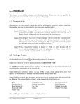
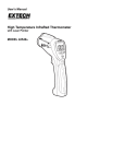
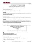
1
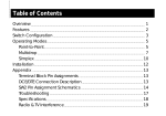
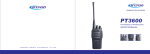
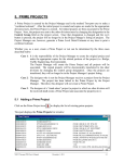
Z-WAVE SMART HOME PRODUCTS
Z-Wave Dimmer Switch TZ65S
Radio Frequency (RF) Controlled, 500W, 230 VAC, European Wall Mounted 3-Way Dimmer, Single Switch, Release 1.1
TZ65S Connections
L: Line voltage input
L': Switched load output
N: Line neutral
3: Auxiliary switch signal input
Note: Note: This module must be “Included in the Network” only where it will be permanently
installed. The proper operation of this node in the mesh network is dependent on it knowing its location with respect to
other nodes. You cannot “test bench” configure this module.
TZ65S Wall Mounted Dimmer
The TZ65S Wall mounted 3-Way Dimmer is a component of the lighting control system.
This wall mounted dimmer is designed to work with other Z-Wave enabled devices.
Z-Wave nodes of other types can be added to the system and will also act as repeaters if they support this function of repeating
the signal received to other modules in the system.
As part of a Z-Wave network, the TZ65S will also act as a wireless repeater to insure that commands intended for another device
in the network are received. This is useful when the device would otherwise be out of the radio range of the wireless controller.
There are no field repairable assemblies on this unit . If service is needed, the unit must be returned where purchased.
Installation
DANGER! SHOCK HAZARD. Read and understand these instructions before installing. It is recommended that a qualified
electrician perform this installation. Make sure the load controlled by the dimmer does not exceed 500W. For indoor use only.
Retain instructions for future use.
Wire this dimmer in place of a current wall switch according to the diagram.
See the wireless controller operating instructions to add this module under the command of the wireless controller.
1. Remove the paddle. Using small screw driver, push out the paddle through holes in back side of mounting plate.
The paddle can also be pried out from the face, from the top or the bottom of the paddle.
2. Remove the four screws through the retaining ring holding the trim ring to the mounting plate. This will allow removal of trim
ring. When removing the trim ring make sure not to bend or disrupt the shape of the antenna wire.
3. Wire the product according to the diagram.
4. Install the product in the wall box.
5. Reinstall the trim ring and the retaining ring with the four screws . Position of this ring is important. The stamped word “Bottom”
on the metal and retaining ring will be aligned with each other. Again do not disrupt the integrity of the antenna wire.
6. Return the paddle to the face of the product . Simply press into place. Make sure the LED window is also toward the stamped
word “Bottom” on the retaining ring.
15/ www.tkbhome.com
Z-WAVE SMART HOME PRODUCTS
Z-Wave Dimmer Switch TZ65S
Including TZ65S To The Network
Including to the network (must be installed in its permanent location , not on test bench)
> Setup the controller you are using to include a device into network.
> Tap either the top or bottom of the switch once.
Excluding from the network
> Setup the controller you are using to exclude a device from the network.
> Tap either the top or the bottom of the switch once.
Basic Operation
(Local control)
The switch on the TZ65S allows the user to:
> Turn ON or OFF the attached load.
> Dimmer the attached load.
> Include or exclude the module from the Z-Wave system.
> Control other Z-Wave enabled devices.
Also, when a controller prompts you to “Send Node ID ” or to “Press Button on Unit”, quickly tap the switch ON or OFF once to
satisfy those instructions.
> Tapping top of switch turns the load attached ON.
> Tapping bottom of switch turns the load attached OFF.
> Pressing and holding the top of the switch, it will brighten the load
> Pressing and holding the bottom of the switch, it will dim the load
> Pressing and holding the switch does not effect the load attached but will allow dimming and brightening of Z-Wave dimmers
if associated.
Caution: When dimmed to the lowest setting , even though the load looks like its off, it still has power. Tap bottom of switch
to turn off completely. It is best to turn off the power at the circuit breaker to service the load.
Note: Upon restoration of power after a power loss, the ZDM230 returns to previous known state.
LED Indication
The LED on the TZ65S will turn on when the load attached is off, to act as a night light. However, the LED can be user configured
to turn on when the load attached is on.
The TZ65S will flicker its LED when it is transmitting to any of the groups. This can be changed if desired. See “LED transmission
indication”.
Remote control
The TZ65S will respond to BASIC and MULTILEVEL commands that are part of the Z-Wave system. Refer to your controller's
instructions as to whether your controller can transmit those commands.
Advanced Operation
All on/All Off
The TZ65S supports the ALL ON/ ALL OFF commands. .
The TZ65S can be set to respond to ALL ON and ALL OFF commands 4 different ways. . Refer to your controller for in formation
on how to set the TZ65S to operate in the manner you desire. Some controllers may be only able to set certain settings of ALL
ON/ALL OFF response The 4 different ways the TZ65S can be setup to respond to ALL ON and ALL OFF commands are:
1.TZ65S Will not respond to ALL ON or the ALL OFF command.
2.TZ65S Will respond to ALL OFF command but will not respond to ALL ON command.
3.TZ65S Will respond to ALL ON command but will not respond to ALL OFF command.
4.TZ65S Will respond to ALL ON and the ALL OFF command.
www.tkbhome.com /16
Z-WAVE SMART HOME PRODUCTS
Z-Wave Dimmer Switch TZ65S
Association
The TZ65S supports the association command.
The TZ65S can be set to control other Z-Wave devices . Those devices must be installed in their permanent location. You can
turn on and off, and even dim other Z-Wave devices once they are “associated” into 1 groups within the TZ66S.
Each group is turned on or off (or dimmed) by tapping or holding the switch a differing amount of times.
Group 1 Control: If you associate a Z-Wave device into Group 1 , you can turn that device ON and OFF by tapping the top or
bottom of the left switch once. The load attached to the TZ65S will also turn on or off.
You can brighten the controlled device by pushing and holding the top of the switch. dim by pushing and holding the bottom
of the switch.
You can associate up to 5 Z-Wave devices into Group 1.
For instructions on how to “associate” a Z-Wave device into the group, refer to your wireless controller instructions.
A note about dimming, if you combine Z-Wave enabled dimmers and other types of Z-Wave devices in a group , place a Z-Wave
enabled dimmer into the empty group first to ensure that the dimming operates correctly.
Configuration
The TZ65S supports the configuration command.
The TZ65S can be configured to operate slightly differently than how it works when you first install it. Using the configuration
command you can configure the following:
> Set Ignore start level bit when transmitting dim command
> Night light operation
> LED transmission indication
You can use a controller to send configuration commands . (Refer to the setup menu, configuration section).
Set Ignore start level bit when transmitting dim commands.
> Parameter No: 1
> Length: 1 Byte
> Valid values = 0 or 1 (default value is 1)
The TZ65S can send dim commands to Z-Wave enabled dimmers. The dim command has a start level embedded in it. A dimmer
receiving this command will start dimming from that start level. However, the command also has a bit that in dicates whether the
dimmer should ignore the start level. If the bit is set to 1 , the dimmer will ignore the start level and instead start dimming from
its current level. If this bit is set to 0, the dimmer will not ignore the start level.
Night light
> Parameter No: 3
> Length: 1 Byte
> Valid values = 0 or 1 (default value is 0)
The LED on the TZ65S will by default, turn ON when the load attached is turned OFF. To make the LED turn ON when the load
attached is turned ON instead, set parameter 3 to a value of 1.
Invert switch
> Parameter No: 4
> Length: 1 Byte
> Valid values = 0 or 1 (default value is 0)
17/ www.tkbhome.com
Z-WAVE SMART HOME PRODUCTS
Z-Wave Dimmer Switch TZ65S
To change the top of the switch to OFF and the bottom of the switch ON , set parameter 4 to 1.
LED transmission indication
> Parameter 19
> Length: 1 Byte
> Valid values = 0, 1, 2 (default value is 2)
The TZ65S will flicker its LED when it is transmitting to any of its 4 groups . This flickering can be set to not flicker at all (set
to 0), to flicker the entire time it is transmitting ( set to 1 ) , or to flicker for only 1 second when it begins transmitting ( set to
2) . By default, the TZ65S is set to flicker for only 1 second.
Each configuration parameter can be set to its default setting by setting the default bit in the configuration set command.
See your controller's instructions on how to do this (and if it supports it).
All configuration commands will be reset to their default state when the TZ65S is reset from the Z-Wave system.
Power level
The TZ65S supports the power level command.
The power level command allows controllers to set and get the RF transmit power level of a node and test specific links between
nodes with specific RF transmit power. Refer to your controller's instructions, if it supports this command, for more information.
This command is typically used by professional installers.
SUC Support
There must be a static update controller in your Z-Wave system for this feature to work. The static controller can act as a gate
way in the system , since other nodes always know its position (not moved after addition to the network).The “always listening”
advantage of the static controller is that other nodes can transmit information frames to it whenever needed.
You can assign an “SU C Route” to the TZ65S. Refer to your controller's instructions on how to do this (if it supports it). Assigning
an SUC Route to the TZ65S allows it to request an update of the Z-Wave devices that are in between it and the Z-Wave device it
was trying to transmit to. The TZ65S will only request an update when a transmission fails.
Specifications
Power:
230 VAC, 50 Hz
Signal (frequency):
868.42 MHz
Maximum Load–Resistive:
500W maximum, 230 VAC
Range:
up to 30 meters line of sight between the Wireless Controller and /
or the closest Z-Wave receiver module
Interoperability With Z-Wave Devices
TZ65S Wiring Diagram
A Z-Wave network can integrate devices of various classes
LOAD
made by different manufacturers.
The TZ65S can be incorporated into existing Z-Wave networks.
The top or bottom of the TZ65S switch can be used to carry
NEUTRAL
out inclusion, association, or exclusion.
LINE
Mounting box size:
Depth: 47mm
LL′N3
Diameter: 66mm
Mounting size: 62mm
TZ65S
www.tkbhome.com /18
Z-WAVE SMART HOME PRODUCTS
Z-Wave Dimmer Switch TZ65D
Radio Frequency Controlled, 500W, 230 VAC, European Wall Mounted 3-Way dimmer , Dual Switch, Release 1.1
TZ65D Connections
L: Line voltage input
L': Switched load output
N: Line neutral
3: Auxiliary switch signal input
Note: This module must be “Included in the Network” only where it will be permanently
installed. The proper operation of this node in the mesh net work is dependent on it knowing its location with respect to
other nodes . You can not “test bench” configure this module, then install.
TZ65D Wall Mounted Dimmer
The TZ65D wall mounted 3-Way dimmer is a component of the lighting control system.
This wall mounted dimmer is designed to work with other Z-Wave enabled devices.
Z-Wave nodes of other types can be added to the system and will also act as repeaters if they support this function of repeating
the signal received to other modules in the system.
As part of a Z-Wave network, the TZ65D will also act as a wireless repeater to insure that commands intended for another device
in the network are received. This is useful when the device would otherwise be out of the radio range of the wireless controller.
There are no field repairable assemblies on this unit . If service is needed, the unit must be returned where purchased.
Installation
DANGER! SHOCK HAZARD. Read and understand these instructions before installing. It is recommended that a qualified electrician
perform this installation. Make sure the load controlled by the switch does not exceed 500W. For indoor use only. Retain
instructions for future use.
Wire this dimmer in place of a current wall switch according to the legend.
See the wireless controller operating instructions to add this module under the command of the wireless controller.
1. Remove the paddle. Using small screw driver, push out the paddle through holes in back side of mounting plate.
The paddle can also be pried out from the face, from the top or the bottom of the paddle.
2. Remove the four screws through the retaining ring holding the trim ring to the mounting plate. This will allow removal of trim ring.
When removing the trim ring make sure not to bend or disrupt the shape of the antenna wire.
3. Wire the product according to the diagram.
4. Install the product in the wall box.
5. Reinstall the trim ring and the retaining ring with the four screws . Position of this ring is important. The stamped word “Bottom”
on the metal and retaining ring will be aligned with each other. Again do not disrupt the integrity of the antenna wire.
6. Return the paddle to the face of the product . These simply press into place. Make sure the LED windows are also toward the
stamped word “Bottom” on the retaining ring.
19/ www.tkbhome.com
Z-WAVE SMART HOME PRODUCTS
Z-Wave Dimmer Switch TZ65D
Including TZ65D To The Network
Including to the network (must be installed in its permanent location , not on test bench)
> Setup the controller you are using to include a device into network.
> Tap either the top or bottom of the switch once.
Excluding from the network
> Setup the controller you are using to exclude a device from the network.
> Tap either the top or the bottom of the switch once.
Basic Operation
(Local control)
The left switch on the TZ65D allows the user to:
> Turn ON or OFF the attached load.
> Include or exclude the module from the Z-Wave system.
> Control other Z-Wave enabled devices.(one “associated” group of 5 each-Groups 1) The right switch on the TZ65D allows the
user to:
> Control other Z-WAVE enable devices (two “associated” group of 5 each-Groups 1) Also, when a controller prompts you to
“Send Node ID ” or to “Press Button on Unit”, quickly tap the switch ON or OFF once to satisfy those instructions.
> Tapping top of left switch turns the load attached ON.
> Tapping bottom of left switch turns the load attached OFF.
> Pressing and holding the top of the switch, it will brighten the load
> Pressing and holding the bottom of the switch, it will dim the load
> Pressing and holding the left switch does not effect the load attached but will allow dimming and brightening of Z-Wave
dimmers if associated . Same for the right switch.
Caution: When dimmed are at the lowest setting, even though the load looks like its off, it still has power. Tap bottom of switch
to turn off completely. It is best to turn off the power at the circuit breaker to service the load.
Note: Upon restoration of power after a power loss , the TZ65D returns to previous known state.
LED Indication
The LED on the TZ65D will turn on when the load attached is off, to act as a night light. However, the LED can be user configured
to turn on when the load attached is on.
The TZ65D will flicker its LED when it is transmitting to any of its 4 groups. This can be changed if desired. See “LED transmission
indication”.
Remote control
The TZ65D will respond to BASIC and MULTIEVEL commands that are part of the Z-Wave system. Refer to your controller's
instructions as to whether your controller can transmit those commands.
Advanced Operation
All on/All Off
The TZ65D supports the ALL ON/ ALL OFF commands. .
The TZ65D can be set to respond to ALL ON and ALL OFF commands 4 different ways. . Refer to your controller for in formation
on how to set the TZ65D to operate in the manner you desire. Some controllers may be only able to set certain settings of ALL
ON/ALL OFF response.The 4 different ways the TZ65D can be setup to respond to ALL ON and ALL OFF commands are:
1.TZ65D Will not respond to ALL ON or the ALL OFF command.
2.TZ65D Will respond to ALL OFF command but will not respond to ALL ON command.
3.TZ65D Will respond to ALL ON command but will not respond to ALL OFF command.
4.TZ65D Will respond to ALL ON and the ALL OFF command.
www.tkbhome.com /20
Z-WAVE SMART HOME PRODUCTS
Z-Wave Dimmer Switch TZ65D
Association
The TZ65D supports the association command.
The TZ65D can be set to control other Z-Wave devices . Those devices must be installed in their permanent location. You can
turn on and off, and even dim other Z-Wave devices once they are “associated” into 1 of 4 groups within the TZ65D.
Each group is turned on or off (or dimmed) by tapping or holding the switch a differing amount of times.
Group 1 Control: If you associate a Z-Wave device into Group 1 , you can turn that device ON and OFF by tapping the top or
bottom of the left switch once. The load attached to the TZ65D will also turn on or off. Associating nodes into Group 2 or 3 will
cause a very slight delay before the command is transmitted to Group 1 nodes.
You can brighten the controlled device by pushing and holding the top of the left switch. Dim by pushing and holding the bottom
of the left switch.
Group 2 Control: If you associate a Z-Wave device into Group 2 , you can turn that device ON and OFF by tapping the top or
bottom of the right switch. You can brighten or dim devices by pushing and holding the top of the right switch. Dim by pushing
and holding the bottom of the right switch. The load attached to the TZ65D is not affected. The LED on the righ switch will
indicate the status of Group 2. Group 2 will be polled at a specific interval and the LED on the right switch will indicate the status
of Group 2. The polling interval can be configured.
Group 3 Control: If you associate a Z-Wave device into Group 3, you can turn that device ON or OFF by tapping the top or
bottom of the right switch twice. You can bright en or dim devices by tapping the switch once then push and hold the top or
bottom of the right switch. The load attached to the TZ65D is not affected.
Group 4 Control: If you associate a Z-Wave device into Group 4, that device will be commanded to turn on or off when the
TZ65D is commanded to turn on or off. Caution: The TZ65D will not transmit to Z-Wave devices in Group 4 if it is already in the
state that the Z-Wave command commanded it to.
You can associate up to 5 Z-Wave devices into each of these groups.
For instructions on how to “associate” a Z-Wave device into one of these groups, refer to your wireless controller instructions.
(If you are using the z-wave controller, refer to the setup menu, association section).
A note about dimming, if you combine Z-Wave enabled dimmers and other types of Z-Wave devices in a group , place a Z-Wave
enabled dimmer into the empty group first to ensure that the dimming operates correctly.
Configuration
The TZ65D supports the configuration command.
The TZ65D can be configured to operate slightly differently than how it works when you first install it. Using the configuration
command you can configure the following:
> Set Ignore start level bit when transmitting dim command
> Suspend group
> Night light operation
> Invert switch
> Poll Group 2 Interval (minutes)
> Poll Group 2
You can use a controller to send configuration commands . (Refer to the setup menu, configuration section).
Set Ignore start level bit when transmitting dim commands.
> Parameter No: 1
> Length: 1 Byte
> Valid values = 0 or 1 (default value is 1)
21/ www.tkbhome.com
Z-WAVE SMART HOME PRODUCTS
Z-Wave Dimmer Switch TZ65D
The TZ65D left switch can send dim commands to Z-Wave enabled dimmers. The dim command has a start level embedded in it.
A dimmer receiving this command will start dimming from that start level. However, the command also has a bit that in dicates
whether the dimmer should ignore the start level. If the bit is set to 1 , the dimmer will ignore the start level and instead start
dimming from its current level. If this bit is set to 0, the dimmer will not ignore the start level.
Suspend Group 4
> Parameter No: 2
> Length: 1 Byte
> Valid values = 0 or 1 (default value is 0)
You may wish to disable transmitting comm a n d s t o Z-Wave devices that are in Group
4 without “disassociating” those devices from the group. Setting parameter 2 to the value of 1 will stop theTZ65D from
transmitting to devices that are “associated” into Group 4.
Night light
> Parameter No: 3
> Length: 1 Byte
> Valid values = 0 or 1 (default value is 0)
The LED on the TZ65D will by default, turn ON when the load attached is turned OFF. To make the LED turn ON when the load
attached is turned ON instead, set parameter
3 to a value of 1.
Invert switch
> Parameter No: 4
> Length: 1 Byte
> Valid values = 0 or 1 (default value is 0)
To change the top of the switch to OFF and the bottom of the switch ON , set parameter 4 to 1.
Note: if you invert the switches and also install the produce upside down , remember the load will now be controlled by the right,
not the left switch.
Poll Group 2 Interval (minutes)
> Configuration Parameter 20.
> One Byte
> Valid Values = 1 through 255 (Default value is 2)
Poll Group 2
> Configuration Parameter 22. (Default value is 1)
> One Byte
> If value is 0, the TZ65D will not poll Group 2.
> If value is 1, the TZ65D will poll Group 2 at the interval set in Configuration
Parameter 20
Enable shade control Group 2
> Parameter 14
> Length: 1 Byte
> Valid values: 0 or 1 (default value is 0)
The TZ65D can operate shade control devices via its Group 2 if this configuration parameter is set to 1.
Enable Shade control Group 3
> Parameter 15
> Length: 1 Byte
> Valid values: 0 or 1 (default value is 0)
www.tkbhome.com /22
Z-WAVE SMART HOME PRODUCTS
Z-Wave Dimmer Switch TZ65D
The TZ65D can operate shade control devices via its Group 3 if this configuration parameter is set to 1.
LED Transmission indication
> Parameter 19
> Length: 1 Byte
> Valid values = 0, 1, 2 (default value is 2)
The TZ65D will flicker its LED when it is transmitting to any of its 4 groups . This flickering can be set to not flicker at all (set
to 0), to flicker the entire time it is transmitting ( set to 1 ) , or to flicker for only 1 second when it begins transmitting ( set to
2) . By default, the TZ65D is set to flicker for only 1 second.
Each configuration parameter can be set to its default setting by setting the default bit in the configuration set command.
see your controller's instructions on how to do this (and if it supports it).
All configuration commands will be reset to their default state when the TZ65D is reset from the Z-Wave system.
Power level
The TZ65D supports the power level command.
The power level command allows controllers to set and get the RF transmit power level of a node and test specific links between
nodes with specific RF transmit power. Refer to your controller's instructions, if it supports this command, for more information.
This command is typically used by professional installers.
SUC Support
There must be a static update controller in your Z-Wave system for this feature to work. The static controller can act as a gate
way in the system , since other nodes always know its position (not moved after addition to the network).The “always listening”
advantage of the static controller is that other nodes can transmit information frames to it whenever needed.
You can assign an “SU C Route” to the TZ65D. Refer to your controller's instructions on how to do this (if it supports it). Assigning
an SUC Route to the TZ65D allows it to request an update of the Z-Wave devices that are in between it and the Z-Wave device it
was trying to transmit to. The TZ65D will only request an update when a transmission fails.
Specifications
Power:
230 VAC, 50 Hz
Signal (frequency):
868.42 MHz
Maximum Load–Resistive:
500W maximum, 230 VAC
Range:
up to 30 meters line of sight between the Wireless Controller and /
or the closest Z-Wave receiver module
Interoperability With Z-Wave Devices
TZ65D Wiring Diagram
A Z-Wave net work can integrate devices of various classes
LOAD
made by different manufacturers.
The TZ65D can be incorporated into existing Z-Wave networks.
The top or bottom of the TZ65D switch can be used to carry
NEUTRAL
out inclusion, association, or exclusion.
LINE
Mounting Box Size:
Depth: 47mm
LL′N3
Diameter: 66mm
Mounting size: 62mm
23/ www.tkbhome.com
TZ65D