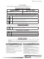
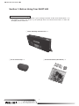
1
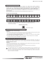
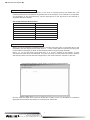
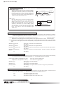
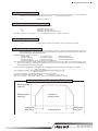
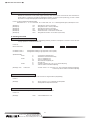
Intelligent Driver
Two-Axis Stage Controller
User's Manual
1-19-9, Midori, SIGMA KOKI Tokyo Head office, Sumida-ku, Tokyo 130-0021, JAPAN
Tel: +81-3-5638-8228 Fax: +81-3-5638-6550 E-mail:sales @sigma-koki.com
Osaka Branch
4-9-28, Nishi-Nakajima, Yodogawa-ku, Osaka 532-0011, JAPAN
Tel: +81-6-6307-4835 Fax: +81-6-6307-4834 E-mail:sales.osaka @sigma-koki.com
Kyushu Sales office
3-17, Hie-machi, Hakata-ku, Fukuoka-shi, Fukuoka 812-0014, JAPAN
Tel: +81-92-481-4300 Fax: +81-92-481-4310 E-mail:sales.kyushu @sigma-koki.com
1-1 Yatsukaho, Hakusan-shi, Ishikawa
Tel: +81-76-274-6100 Fax: +81-76-274-6103
924-0838, JAPAN
2010.11. Fourth edition
Table of Contents
For your safety ‥ ‥‥‥‥‥‥‥‥‥‥‥‥‥‥‥‥‥‥‥‥‥‥‥‥‥‥‥‥‥‥‥ 1
Section 1: Before Using Your SHOT-602‥ ‥‥‥‥‥‥‥‥‥‥‥‥‥‥‥‥‥‥ 2
1-1. Check Inside the Package‥‥‥‥‥‥‥‥‥‥‥‥‥‥‥‥‥‥‥‥‥‥‥‥ 2
1-2. Outline‥ ‥‥‥‥‥‥‥‥‥‥‥‥‥‥‥‥‥‥‥‥‥‥‥‥‥‥‥‥‥‥‥ 3
1-3. SHOT-602 System Diagram‥‥‥‥‥‥‥‥‥‥‥‥‥‥‥‥‥‥‥‥‥‥‥ 3
1-4. Names and Functions of Each Part‥‥‥‥‥‥‥‥‥‥‥‥‥‥‥‥‥‥‥‥ 4
Section 2: Basic Operations‥ ‥‥‥‥‥‥‥‥‥‥‥‥‥‥‥‥‥‥‥‥‥‥‥‥‥ 6
2-1. Initialize SHOT-602‥‥‥‥‥‥‥‥‥‥‥‥‥‥‥‥‥‥‥‥‥‥‥‥‥‥‥ 6
2-2. Set Parameters with DIP Switch‥ ‥‥‥‥‥‥‥‥‥‥‥‥‥‥‥‥‥‥‥‥ 6
2-3. Adjust Drive (RUN, STOP) Current‥‥‥‥‥‥‥‥‥‥‥‥‥‥‥‥‥‥‥‥ 7
2-4. Connection between SHOT602 and Motorized Stage‥‥‥‥‥‥‥‥‥‥‥‥ 7
2-5. Connection between SHOT602 and Host (PC, etc) ‥‥‥‥‥‥‥‥‥‥‥‥‥ 7
2-6. Environment Settings of Host ‥‥‥‥‥‥‥‥‥‥‥‥‥‥‥‥‥‥‥‥‥‥ 8
2-7. Power ON and Check Communications ‥ ‥‥‥‥‥‥‥‥‥‥‥‥‥‥‥‥ 8
Section 3: Commands for SHOT-602‥ ‥‥‥‥‥‥‥‥‥‥‥‥‥‥‥‥‥‥‥‥ 9
3-1. Command List‥‥‥‥‥‥‥‥‥‥‥‥‥‥‥‥‥‥‥‥‥‥‥‥‥‥‥‥‥ 9
3-2. Function and Format of Command‥ ‥‥‥‥‥‥‥‥‥‥‥‥‥‥‥‥‥‥‥ 9
Section 4: Specifications‥‥‥‥‥‥‥‥‥‥‥‥‥‥‥‥‥‥‥‥‥‥‥‥‥‥ 13
4-1. General specifications‥‥‥‥‥‥‥‥‥‥‥‥‥‥‥‥‥‥‥‥‥‥‥‥‥ 13
4-2. Performances‥ ‥‥‥‥‥‥‥‥‥‥‥‥‥‥‥‥‥‥‥‥‥‥‥‥‥‥‥ 14
4-3. SHOT-602 Case Drawing‥‥‥‥‥‥‥‥‥‥‥‥‥‥‥‥‥‥‥‥‥‥‥ 15
■ SHOT-602 User’s Manual
■
For Your Safety
◦ Before using this product, read this manual and all warnings or cautions in the documentation provided.
◦ Only Factory Authorized Personnel should be changes and/or adjust the parts of controller.
The Symbols Used in This Manual
WARNING
CAUTION
This symbol marks warnings that should be read and used to
prevent serious injury or death.
This symbol indicates where caution should be used to avoid
possible injury to yourself or others, or damage to property.
The above indications are used together with the following symbols to indicate the exact nature of the warning or caution.
Examples of Symbols Accompanying Warnings and Cautions
△ Symbols enclosed in a triangle indicate warnings and cautions. The exact nature of the warning or
caution is indicated by the symbol inside (the symbol at left indicates risk of electrocution).
○ Symbols enclosed in a circle mark indicate prohibitions (actions that must not be performed). The exact
nature of the prohibition is indicates by the symbol inside or next to the circle mark (the symbol at left
indicates that the product must not be disassembled).
● Symbols inside a black circle mark actions that must be performed to ensure safety. The exact nature of
the action that must be performed is indicated by the symbol inside (the symbol at left is used in cases in
which the AC adapter must be unplugged to ensure safety).
Symbols on the product
The symbol mark on the product calls your attention. Please refer to the manual, in the case that you operate the part of the symbol
mark on the product.
This symbol labeled on the portion calls your attention.
Symbols Used in This Manual
The following symbols are used in this manual.
This symbol is used to indicate cross-references to relevant information in this manual or other documentation.
This symbol marks items that should be confirmed before an operation (or action) is performed.
This symbol marks definitions of terms and other useful information.
(Note)
This symbol marks supplementary information.
Disclaimer of Liability
①
②
③
④
SIGMA KOKI CO., LTD. does not accept liability for damages resulting from the use of this product or the inability to use this product.
SIGMA KOKI CO., LTD. does not accept liability for damages resulting from the use of this product that deviates from that described
in the manual.
SIGMA KOKI CO., LTD. does not accept liability for damages resulting from the use of this product in extraordinary conditions,
including fire, earthquakes, and other acts of God, action by any third party, other accidents, and deliberate or accidental misuse.
If the equipment is used in a manner not specified by the SIGMA KOKI CO., LTD., the protection provided by the equipment may be
impaired.
WARNING
CAUTION
◦ Do not use this product in the presence of flammable gas, explosives,
or corrosive substances, in areas exposed to high levels of moisture or
humidity, in poorly ventilated areas, or near flammable materials.
◦ Do not connect or check the product while the power is on.
◦ Installation and connection should be performed only by a qualified
technician.
◦ Do not bend, pull, damage, or modify the power or connecting cables.
◦ Do not touch the products internal parts.
◦ Connect the earth terminal to ground.
◦ Should the product overheat, or should you notice an unusual smell,
heat, or unusual noises coming from the product, turn off the power
immediately.
◦ Do not turn on the power in the event that it has received a strong physical
shock as the result of a fall or other accident.
◦ Do not touch the stage while operation.
◦ Use dry clothes only for cleaning the equipment.
1
◦ Do not leave the product in an enclosed area or in areas in which it would
be exposed to direct sunlight or vibration.
◦ Do not touch the product when your hands are wet.
◦ When unplugging the product, pull on the plug rather than the cord.
◦ Because some electrical change remains after the power has been cut, do
not touch the input or output terminals for ten seconds after the product
has been turned off.
◦ When connecting peripherals to the product, adjust the product's initial
setting (parameter settings) to suit the peripheral.
◦ Turn off the power before connecting the product to other devices.
Connection should be performed following the connection diagram.
◦ Before turning the equipment on (or when beginning operations), be
sure that you can turn the power off immediately in the event that an
abnormality should occur.
◦ Do not obstruct the product's air vents or other openings.
◦ For continued protection against risk of fire, replace only with same type
and rating fuse. Fuse replacement is done by a qualified technician.
Tokyo Head office Tel:+81-3-5638-8228
Fax:+81-3-5638-6550
E-mail:[email protected]
■ SHOT-602 User’s Manual ■
Section 1: Before Using Your SHOT-602
1-1 Check Inside the Package
Before you use this controller, check if your package includes all the items listed below. It is
convenient to check in the boxes: If your package does not include all the items, or items are
damaged, please contact us.
□ SHOT-602 Stage Controller Unit : 1
□ PC-5K Terminal Cap : 1
Tel:+81-6-6307-4835
Fax:+81-6-6307-4834
E-mail:[email protected]
Osaka branch
□ Instruction Manual (This Manual) : 1
2
■ SHOT-602 User’s Manual
■
1-2 Outline
This controller is a twin-axis stage controller featuring stepping motor drivers.
Keeping compatibility with existing models, the controller features versatility that can support wide
variety of your needs as well as delightfully low price.
Connect the unit to your standard PC via RS-232C interface, and you can send simple commands
from PC for moving motorized stages precisely to a target position.
Simple programming offered allows you to easily configure a controlling system of considerable
scale.
1-3 SHOT-602 System Diagram
SHOT-602 incorporates stepping motor drivers, which enable you to design a low cost, spaceefficient system with our SGSP series or other motorized stages driven by stepping motors,
connected with standard cables.
SHOT-602 System Diagram
Note that applicable cables and drive current values are depending on the specifications of
stages used. Check if your controller can adequately control desired devices before forming a
system.
You cannot connect SCT-602(PC-5K)and PC to a SHOT-602 controller at the same time. If
you connect them in parallel, SHOT-602, SCT-602(PC-5K), and/or PC may be damaged.
3
Tokyo Head office Tel:+81-3-5638-8228
Fax:+81-3-5638-6550
E-mail:[email protected]
■ SHOT-602 User’s Manual ■
1-4 Names and Functions of Each Part
Functions
① Turn ON the power switch (turn to“|”mark) to supply power and light up LED indicator ④ . Turn the switchto OFF “O”
(
)
to turn OFF the power and the indicator. and the indicator.
② Use when you want to use your PC for controlling via RS-232C interface.
③ Use when controlling with the PC-5K intelligent controller.
④ Lights up in green while the power is turned ON.
⑤ Lights up in red while driving stages.
⑥ Should be grounded properly in your environment.
⑦ Connect a stage used as Axis 1.
⑧ Connect a stage used as Axis 2.
Tel:+81-6-6307-4835
Fax:+81-6-6307-4834
E-mail:[email protected]
Osaka branch
4
■ SHOT-602 User’s Manual
■
⑨ Makes basic settings for your SHOT-602.
⑩ Volume control adjusting the RUN current output through the stage drive connector (Axis 1).
⑪ Volume control adjusting the STOP current output through the stage drive connector (Axis 1).
⑫ Volume control adjusting the RUN current output through the stage drive connector (Axis 2).
⑬ Volume control adjusting the STOP current output through the stage drive connector (Axis 2).
5
Tokyo Head office Tel:+81-3-5638-8228
Fax:+81-3-5638-6550
E-mail:[email protected]
■ SHOT-602 User’s Manual ■
Section 2: Basic Operations
2-1 Initialize SHOT-602
Initialize your SHOT-602 to match to the target stages and host environment (your PC, etc). The
initialization includes DIP switch settings and current adjustments (RUN/STOP) for each axis motor.
2-2 Set Parameters with DIP Switch
Initialize your SHOT-602 by setting each switch to ON/OFF as follows:
Parameter Assignment in the DIP Switch:
DIP switch No.
Items
Parameters
1,2
Baud rate
2400/4800/9600/19200
3
Detecting the mechanical origin
SIGMA system / MINI system
4
Input logic for the limit sensor
Normal open / Normal close
5
Specify whether to return to mechanical origin for each axis
First axis only / Both axis
Switch Settings and Corresponding Parameters
(Set to ON by turning to the number-marked side on the switch body)
Items
Dip switch No.
SW2
Baud rate
Descriptions
SW1
ON
ON
2400
ON
OFF
4800
OFF
ON
9600
OFF
OFF
19200
SW3
Detecting the mechanical origin
ON
SIGMA method
OFF
MINI method
SW4
Input logic for the limit sensor
Specify whether to return to
mechanical origin for each axis
ON
Normal open
OFF
Normal close
SW5
ON
First axis only
OFF
Axes1 and 2
NOTE: Shaded areas in the list show our factory settings. Take care to handle the very small DIP
switch so as to avoid giving damage to them during the settings. Use appropriate tools such as
sharp tweezers for setting switches on the DIP switch.
For our SGSP series stages, select Normal Close for the limit sensor logic and MINI for the homing
method.
See Detection of Machine Home Position in p.10 for the details of the homing method.
Tel:+81-6-6307-4835
Fax:+81-6-6307-4834
E-mail:[email protected]
Osaka branch
6
■ SHOT-602 User’s Manual
■
2-3 Adjust Drive (RUN, STOP) Current
Set current values supplied from SHOT-602 to stages. Turn a RUN current volume, provided on
the side of the unit, to adjust RUN current corresponding to the stages to use. Use a STOP current
volume to set a ratio to RUN current according to your conditions for the case where the current
down function works. You can make each current adjustment for Axis 1 or Axis 2 independently.
Note that for the STOP current, adjustment is available not for current values, but for a ratio (%) to
the RUN current.
Note: Generally the ratio of the STOP current to the RUN current is approx. 50 %.
Driving current settings (RUN)
Volume No
0
1
2
3
4
5
6
7
8
9
10
Amperage
〔A〕
0.17
0.25
0.33
0.40
0.47
0.54
0.61
0.67
0.73
0.79
0.85
Stop current settings(Stop current setting to 50% for RUN current)
RUN volume No
0
1
2
3
4
5
6
7
8
9
10
STOP volume No.
0
1
1
1
1
1
2
2
2
2
2
Note: Each value cited in the above table is a guide to adjust the current without
instruments, and may fluctuate within an allowable range. Shaded values in the
list are factory settings.
(Example) Volume setting
(Set to"5"in this figure).
2-4 Connection between SHOT-602 and Motorized Stage
Connect SHOT-602 to motorized stages.
Procedure:
① First, make sure that the power plug of SHOT-602 is removed from the receptacle, and its power switch is turned
OFF. Follow this step exactly to avoid possible electric shocks or damage to your unit.
② Connect the cable to motorized stages. Select cables correctly matching to your SHOT-602 and stages. DMINISCA or DBCS series cables are applicable to SHOT-602.
③ Connect the stage for Axis 1 to STAGE 1 connector on SHOT-602. Connect the stage for Axis 2 to STAGE 2.
If you want to use only one axis, use STAGE 1 for the connection.
2-5 Connection between SHOT-602 and Host (PC, etc)
Connect SHOT-602 and Host (PC, etc) to send/receive controlling commands. Two types of
interfaces are available; RS232C and the PC-5K intelligent controller. The following descriptions
premise the RS232C interface.
Procedure:
① Use a genuine cable RS232C/STR, or 9-pin, D-SUB straight cable with male/female ends using inch screw threads.
② Make sure the power is turned OFF on both PC and SHOT-602.
③ Insert the male connector of the communications cable into the RS232C terminal on the SHOT-602.
④ Insert the female end into the serial port on your PC.
You should select only one of RS232C and the PC-5K interface as your interface for the
connection. Connecting your units to both interface connectors may damage the units. When
you are not using the PC-5K terminal, cover it with the attached cap. See the instructions
manual of PC-5K for the details.
7
Tokyo Head office Tel:+81-3-5638-8228
Fax:+81-3-5638-6550
E-mail:[email protected]
■ SHOT-602 User’s Manual ■
2-6 Environment Settings of Host
Configure communications environment on the host for communicating with SHOT-602. The
following descriptions use Windows HyperTerminal as the example. For the details of configuration
and operations of the HyperTerminal, see the descriptions in the Appendix of this manual or
applicable Windows manual.
Set Communications Environment:
Items
Descriptions
Bits/second
Baud rate set with DIP switch
Data Bit
8bits
Parity
None
Stop Bit
1bit
Flow Control
Hardware
Emulation
Automatic detection
Delimiter(newline character at the end of a line)
Insert(CR+LF)
2-7 Power ON and Check Communications
When you have completed procedures above, connect the power plug of the SHOT-602 to the
receptacle, and turn ON the power switch (turn to“|”mark). SHOT-602 is turned ON and the green
power indicator LED lights up. Next, enable communications using the HyperTerminal.
Press“Q:”on your key board, and check that“0, 0, K,K,R”appears on the display. If other
characters than the above are displayed, turn OFF the power for SHOT-602 and check if settings
with the DIP switch coincide with the configuration of the communications software on the host.
HyperTerminal Display (typical display of successful communications)
Now the setup has been done, and your SHOT-602 is ready to use. For the details of commands
applicable to SHOT-602, see Section 3: Commands for SHOT-602.
Tel:+81-6-6307-4835
Fax:+81-6-6307-4834
E-mail:[email protected]
Osaka branch
8
■ SHOT-602 User’s Manual
■
Section 3: Commands for SHOT-602
3-1 Command List
Listed below are all the commands used with SHOT-602:
Command
String
Details
Return to mechanical origin
H:
Detect mechanical origin
Set electronic(logical)origin
R:
Set the electronic(logical)origin to the current position
Speed settings
D:
Set S, F, and R
Set number of pulses forrelative movement
M:
Axis of movement, direction, number of pulses
Jog command
J:
Move at minimum speed (S)
Drive command
G
Start
Stop
L:
Stop or reduce speed
Free motor
C:
Excitation ON/OFF
Status1
Q:
Return current position etc.
Status2
!:
Return B (Busy)/R (Ready)
Internal information
?:
Check internal information
NOTE: Only“G”command does not have a colon(“:”)at the end.
3-2 Function and Format of Command
SHOT-602 uses upper-case, one-byte characters. Except for some status check commands, no
response will be returned to a command input. Some commands need parameters.
1) Control (drive system) Command 1
(1) H command: Machine Home Return Command
Function: Detects the machine zero on the stage, and define the position as the home position. Detection of a machine zero
sets the display to“0.”
To detect the zero, each axis moves at the following constant conditions: Minimum speed (S): 500 pps, Maximum
speed (F): 5000 pps, Acceleration/Deceleration time (R): 200 ms. Axes to home are depending on the DIP switch
settings.
Format: H:[Axis number to home][Direction of the Axis 1]
H:W[Direction of Axis 1][Direction of Axis 2]
Returns only one axis to home position.
Returns both axes to home position.
Use parameters“1”or“2”to specify each axis. For both axes, write“W.”Use“+”or“-”as direction parameters. Do not
insert a space, etc. between parameters.
[Example 1]
H:1+
Detects machine zero for Axis 1 in the positive direction.
[Example 2]
H:1-
Detects machine zero for Axis 1 in the negative direction.
[Example 3]
H:2+
Detects machine zero for Axis 2 in the positive direction.
[Example 4]
H:2- Detects machine zero for Axis 2 in the negative direction.
[Example 5]
H:W++ Detects machine zero for Axes 1 and 2, both in the positive direction.
[Example 6]
H:W+- Detects machine zero for Axis 1 in the positive direction, and Axis 2 in the negative
direction.
[Example 7]
H:W-+ Detects machine zero for Axis 1 in the negative direction, Axis 2 in the positive
direction.
[Example 8]
H:W-- Detects machine zero for Axes 1 and 2, both in the negative direction.
Note: With“H:W,”
“L:1”or“L:2”practically means“L:E.”
9
Tokyo Head office Tel:+81-3-5638-8228
Fax:+81-3-5638-6550
E-mail:[email protected]
■ SHOT-602 User’s Manual ■
Detecting the Mechanical Origin
MARK (Sigma) system
When the command is given to detect the mechanical origin, the
stage begins moving clockwise (i.e., in the -direction) at 5000pps
stopping when the clockwise (-) limit sensor is detected. It then
movescounter-clockwise (i.e., in the + direction) at 500pps until
the origin proximity sensor is detected, at which point itreduces
speed to 1/10. The stage continues moving until theorigin sensor
is detected and then stops (CKR series, etc.).
5000pps CW (−)
500pps
CCW(+)
CW ( )
limit sensor
Stage
50pps
CCW(+)
Origin proximity
sensor
Origin sensor
MINI system
When the command is given to detect the mechanical origin, the
stage begins moving clockwise (i.e., in the -direction) at the
5000pps stopping when the clockwise (-) limit sensor is detected.
It then moves counter-clockwise (i.e., in the + direction) at
5000pps for 1000 pulses. After stopping, it begins moving
clockwise (i.e., inthe-direction) once more at 500pps, stopping
when the clockwise (-) limit sensor is reached. It then moves
counter-clockwise (i.e., in the + direction) at 5000pps for 1000
pulses. This position is taken as the mechanical origin
(SGSP series).
5000pps
CW( )
CCW(+)
Move 1000 pulses at 5000pps
CW( )
500pps
CCW(+)
Move 1000 pulses at 5000pps
Stage
CW (–) limit sensor
(2) M command: Command to Set Relative Move Pulse Count
Function: A command to specify axes to move, moving direction and relative moving distance. After executing this command,
make sure to add the driving command,“G.”The movement is acceleration/deceleration drive. Set a pulse count for
a relative moving distance. A pulse count should be +/- 16777214.
Format: M:[Axis number to move][Direction of move]P[Pulse count for moving]
Moves only one axis.
M:W[Direction of Axis 1]P[moving pulse count for Axis 1][Direction of Axis 2]P[moving pulse count for Axis 2] Moves both axes.
Note: If you set a pulse count exceeding a moving limit of a stage, the stage move will be forced to stop on site is detected by
the limit sensor. Valid ranges of pulse counts are depending on stage specifications.Check for the specifications of each
stage.
[Example 1] M:1+P1000 G
[Example 2] M:2-P9000 G
[Example 3] M:W+P500-P200
G
[Example 4] M:W+P50-P20
direction.
G
:Moves Axis 1 1000-pulse in the positive direction.
:Start driving
:Moves Axis 2 9000-pulse in the negative direction.
:Start driving
:Moves Axis 1 500-pulse in the positive direction, and Axis 2 200-pulse in the negative direction.
:Start driving
:Moves Axis 1 50-pulse in the positive direction, and Axis 2 20-pulse in the negative
:Start driving
(3) J command: Jogging Command
Function: A command that moves stages in continuous (constant speed) driving mode at the startup speed (S). After executing
this command, make sure to add the driving command,“G.”The stage will stop by an L command.
Format: J:[Axis number to move][Direction of move]
J:W[Direction of Axis 1][Direction of Axis 2]
[Example 1] J:1+
G
[Example 2] J:2-
G
[Example 3] J:W-+
G
Drives only one axis in jogging mode.
Drives both axes in jogging mode.
:Axis 1 will jog in the positive direction.
:Start driving
:Axis 2 will jog in the negative direction.
:Start driving
:Axis 1 will jog in the negative direction, and Axis 2 will jog in the positive direction.
:Start driving
(4) R command: Electronic (Logical) Zero Return
Function: Set the stopping position as the origin of the coordinate system. On turning ON the power, the position then will
become the origin (displayed“0”). Executing this command will set the display value to“0.”
R:1
R:2
R:W
:Sets Electronic (logical) zero for Axis 1.
:Sets Electronic (logical) zero for Axis 2.
:Sets Electronic (logical) zero for both Axes 1 and 2.
Tel:+81-6-6307-4835
Fax:+81-6-6307-4834
E-mail:[email protected]
Osaka branch
10
■ SHOT-602 User’s Manual
■
(5) G Command: Driving Command
Function: Executing a driving command starts stages, which will stop after moving preset pulses. M or J command should be
followed by a G command. Note that do not add a colon (“:”) at the end of a G command.
G
:Starts to drive stages.
(6) L Command: Deceleration and Stop Command
Function: Executing an L command will decelerate and stop stages.
L:1
:Decelerates and stops Axis 1.
L:2
:Decelerates and stops Axis 2.
L:W
:Decelerates and stops both Axes 1 and 2
Note: When writing“H:,”specifying“L:1”or“L:2”practically means L:E, or stopping of all axes.
(7) L:E: Emergency Stop Command
Function: Stops stages in any states.
L:E
:Terminates the movement of both Axes 1 and 2 in emergency stop mode.
(8) D Command: Command to Set Speed
Function: On turning ON the power, Minimum speed (S), Maximum speed (F), and Acceleration/Deceleration time (R) are
initialized depending on parameters the D command specifies. A D command can change these initial settings. The
default is 2S500F5000R200S500F5000R200.
Effective parameter ranges are as follows:
Speed setting
1: Low Speed Range
2: High Speed Range
Minimum speed (S) 1-200 pps (Low range),
50-20000 pps (High range)
Maximum speed (F)
1-200 pps (Low range),
50-20000 pps (High range)
Acceleration/Deceleration time (R) 0-1000 ms (for both High/Low)
Note: The maximum speed (F) setting should be equal or greater than the minimum speed. If the minimum speed is set to
equals to the maximum or the acceleration/deceleration time is set to zero, stages will move at a constant speed without
performing acceleration/deceleration logically
Format: D:[Speed range]S[Minimum speed]F[Maximum Speed]R[Acceleration/Deceleration time] S[Minimum speed for
|----------------Axis1 parameters--------------------------------------------------------|-------------------------------------Axis 2] S[Minimum speed for Axis 2]F[Maximum speed]R[Acceleration/Deceleration time]
----------------------------------------------Axis 2 parameters-----------------------------------------------|
If you want to use Axis 1 only, input parameters for Axis 2 as dummy data.
[Example 1] D:2S100F1000R200S100F1000R200
Sets speeds for Axes 1 and 2:
(Axis 1: S = 100 pps/F = 1000 pps/ R = 200 ms, Axis 2: 2S = 100 pps/F=1000 pps/R = 200 ms)
Acceleration and Deceleration Patterns
Maximum pulse
speed (F)
Minimum pulse
speed (S)
Acceleration
time (Rms)
Number of
pulses moved
Positioning time
11
Deceleration
time (Rms)
Tokyo Head office Tel:+81-3-5638-8228
Fax:+81-3-5638-6550
E-mail:[email protected]
■ SHOT-602 User’s Manual ■
(9) C Command: Motor Free/Hold (Deenergize/Energize) Command
Function: Deenergizes (motor free) or Energizes (hold) the motor.
Execute this command to move (rotate) stages manually. Note that once this command has been executed, the
actual positions of stages do not match the displayed coordinates. To perform correct positioning, you have to match
the positions of stages and displayed coordinates by the homing operation.
Format: C:[Axis number][Deenergize/Energize]
Parameters are“1”or“2”for each axis,“W”for both axes, and“0/1”to deenergize/energinze (free/hold) the motor.
[Example 1]
[Example 2]
[Example 3]
[Example 4]
[Example 5]
[Example 6]
C:10
C:11
C:20
C:21
C:W0
C:W1
:Sets the Axis 1 motor to free state.
:Energizes the Axis 1 motor (hold state).
:Sets the Axis 2 motor to free state.
:Energizes the Axis 2 motor (hold state).
:Sets both the Axis 1 and 2 motors to free state.
:Energizes both the Axis 1 and 2 motors (hold state).
2) Checking Command
(1) Q Command: Status 1 Command
Function: A command to check the validity of an immediately preceding command, and request a controller to return the state
of stage operations, coordinates of axes, etc.
Format: Q:
Return data format:
Coordinate of Axis 1
Coordinate of Axis 2
ACK1 , ACK2 , ACK3
alphabetical data
Ten-digit data including a sign (if positive, insert a space)
Ten-digit data including a sign (if positive, insert a space)
Alphabetical data
ACK1
ACK2
ACK3
[Example] 9170,-
- 100 , - 200 , Coordinate of Axis 1
Coordinate of Axis 2
X
K
L
M
W
K
B
R
7078,K,K,R
: Command or parameter error
: Received a command successfully
: Axis 1 is stopped by LS.
: Axis 2 is stopped by LS.
: Both axes are stopped by LS.
: Normal stop
: Unable to receive H, R, D, M, J or C commands (Busy)
: Able to receive all commands (Ready)
: Position of Axis 1 is +9170, Axis 2 is -7078, command received successfully,
normal stop, able to receive all commands (Ready)
(2) ! Command: Status 2 Command
Function: The command to request a stage to return the state of stage conditions (Busy/Ready).
Format: !:
[Example]
B
R
: Busy: Only the L, Q or ! commands are acceptable.
: Ready: Able to accept all commands.
(3) ? Command: Command to Acquire Internal ROM Version
Function: The command to request an internal ROM version from the controller.
Format: ?:V
[Example]
V2.00
: Internal ROM version 2.00
Tel:+81-6-6307-4835
Fax:+81-6-6307-4834
E-mail:[email protected]
Osaka branch
12
■ SHOT-602 User’s Manual
■
Section 4: Specifications
4-1 General Specifications
Power Source
Operating Temperature
Ambient Humidity
Storage Temperature
Outer Dimensions
Weight
Installation Category
Pollution degree
: AC100-120V, 50/60 Hz, 50VA
: 5 to 40 °C
: 20 to 85% RH (without condensation)
: -20 to 60 °C
: 234 W x 40 H x 114 D (in mm) ※ Excluding protrusions
: 1.6 kg
:Ⅱ
:2
Driver Specifications
Applicable Motor Type
Driving Mode
Drive (RUN) Current
Stop (STOP) Current
Current Down Function
Motor Free Function
: 5-phase stepping motor
: Half step driving
: 0.17 to 0.85 A/phase
: 0.09 (at 0.17 A RUN current) to 0.69 (at 0.85 A RUN current) A/phase
: Automatic current down
: Switchable motor state (Hold/Free) with C command
Interfacing Specifications
RS232C Terminal
Connector
Baud Rate
Data Length
Parity
Stop bit
Delimiter
: 9-pin, D-SUB female connector (inch screw threads)
: 2400/4800/9600/19200 (set with switches 1/2 on DIP switch)
: 8 bits
: None
: 1 bit
: CR+LF
PC-5K Terminal
Connector
: 9-pin, D-SUB male connector (mm screw threads)
Remarks:
: Output +24 V for PC-5K to pin No. 1.
Do not connect any other devices to the PC-5K terminal to avoid possible damage.
You cannot connect to the PC-5K terminal and RS232C terminal at the same time.
Details of RS232C Connector
Pin No.
1
2
3
4
5
6
7
8
9
Name
NC
TXD
RXD
DSR
SG
DTR
CTS
RTS
NC
Connector Type: 9-pin,D-SUB female connector (inch screw threads)
Details of PC-5K Connector
Pin No.
1
2
3
4
5
6
7
8
9
Name
+24V
TXD
RXD
DSR
SG
DTR
CTS
RTS
EMG
Connector Type: 9-pin,D-SUB male connector (mm screw threads)
13
Tokyo Head office Tel:+81-3-5638-8228
Fax:+81-3-5638-6550
E-mail:[email protected]
■ SHOT-602 User’s Manual ■
4-2 Performances
Number of Controllable Axes
Coordinate Setting Range
Minimum Driving Frequency
Maximum Driving Frequency
Acceleration/Deceleration Time
Sensor Input
: 2 axes (maximum)
: ±16777214 pulses
: 1 pps
: 20 kpps
: 0-1000 ms
: Home sensor (ORG)
: Proximity sensor (NEAR)
: CW (-) limit sensor (motor side)
: CCW (+) limit sensor
Logic can be changed with the settings of switch 4 on the DIP switch.
Homing Method the
Axes to Home
: SIGMA method/MINI method (Set with switch 3 on the DIP switch)
: Axis 1/Axes 1 and 2 (set with switch 5 on the DIP switch)
Tel:+81-6-6307-4835
Fax:+81-6-6307-4834
E-mail:[email protected]
Osaka branch
14
■ SHOT-602 User’s Manual
■
4-3.SHOT-602 Case Drawing
※ Excluding protrusions
Weight:1.6 kg
15
Tokyo Head office Tel:+81-3-5638-8228
Fax:+81-3-5638-6550
E-mail:[email protected]
Intelligent Driver
Two-Axis Stage Controller
User's Manual
1-19-9, Midori, SIGMA KOKI Tokyo Head office, Sumida-ku, Tokyo 130-0021, JAPAN
Tel: +81-3-5638-8228 Fax: +81-3-5638-6550 E-mail:sales @sigma-koki.com
Osaka Branch
4-9-28, Nishi-Nakajima, Yodogawa-ku, Osaka 532-0011, JAPAN
Tel: +81-6-6307-4835 Fax: +81-6-6307-4834 E-mail:sales.osaka @sigma-koki.com
Kyushu Sales office
3-17, Hie-machi, Hakata-ku, Fukuoka-shi, Fukuoka 812-0014, JAPAN
Tel: +81-92-481-4300 Fax: +81-92-481-4310 E-mail:sales.kyushu @sigma-koki.com
1-1 Yatsukaho, Hakusan-shi, Ishikawa
Tel: +81-76-274-6100 Fax: +81-76-274-6103
924-0838, JAPAN
2010.11. Fourth edition