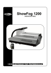
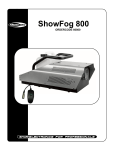
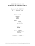
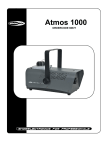
1
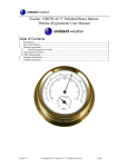
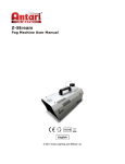
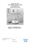
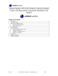
Heating, Air Conditioning, Ventilation Отопление-Кондиционеры-Вентиляция MTM 8-30 kW UNIVERSAL OIL HEATER OPERATING MANUAL 1. Usage MTM 8-30 universal oil heater is designed for heating commercial rooms which are not equipped with central heating systems such as workshops, car service centres, industrial buildings, warehouses, livestock buildings, basements, garages etc. The heater can be powered by most waste oils e.g. motor oil, gear oil, hydraulic oil, diesel fluid and HBO type I, II and III oils whose viscosity is no higher than SAE 80. DO NOT USE TRANSFORMER OILS. THEY MAY CONTAIN SUBSTANCES WHICH CAN DAMAGE THE HEATER. 2. Environmental conditions of storage MTM 8-30 universal oil heater must be stored in the following conditions: • temperature -20..85°C • relative humidity 5..85% • atmospheric pressure 800..1200hPa • dust-free environment • environment free of chemical pollution. 3. Environmental conditions of use MTM 8-30 universal oil heater must be used in the following conditions: • temperature 0..30°C • relative humidity 5..85% • atmospheric pressure 800..1200hPa • Ingress Protection Rating IP65 • well ventilated rooms. 4. Controller characteristics • three power settings 8-19-30 kW, • power setting is stored in the event of a power cut. 5. Security aspects MTM 8-30 universal oil heater is powered by AC 230V/50Hz. The heater is equipped with three sensors which ensure the safe and economical operation of the device. 1. The capillary tube sensor located near the furnace chamber causes the contacts in the thermostat to close when the temperature rises to over 30 °C and open when the temperature falls below 30 °C. 2. The bimetallic sensor located near the ventilation fan, whose threshold temperature is 100 °C, opens the contacts if the threshold temperature is exceeded and causes the heater to go into emergency mode by stopping the flow of fuel, which prevents the fan from overheating or melting of its parts. 3. Micro switch, weight sensor located below the furnace chamber. If the overflow tray is filled, the heater immediately goes into emergency mode and stops the flow of fuel which prevents the surplus of unevaporated fuel from flowing outside of the furnace chamber and eliminates the possibility of fuel ignition outside of the device. The assembly of the heater control panel with other parts of the system such as sensors, pump and fan is made by the manufacturer and during the regular operation, due to safety reasons, it is prohibited to access the covered and sealed part of the heater controller or to disrupt the wiring. Any such unauthorised activities may result in electric shock (230V AC, 50 Hz) or burns. 6. MTM 8-30 Heater design BIMETALLIC TEMPERATURE SENSOR (STB) RESET FAN TOP COVER CAPILLARY OF CONTROL THERMOSTAT FURNACE CHAMBER COVER CONTROLLER FUME EXHAUST FUEL TANK FURNACE CHAMBER FUEL NOZZLE (BURNER) WEIGHT OVERFLOW SENSOR DWG. 1. MTM 8-30 Heater design DWG. 2. MTM 8-30 Heater controller block diagram 7. Installation - Observe the local regulations. Position the heater on a flat and solid surface. Level the heater. In order to ensure the optimum chimney flue, install at least 5 metre long, smooth, high temperature resistant vertical flue made from acid-resistant steel (do not use aluminium flues). Check all connections for tightness. Use electrical tape if necessary. Ensure that all elements are correctly positioned in the furnace chamber and the burner is inserted tightly. Check power supply (220-240V/50Hz) by plugging in the heater and turning the 0/1 switch on. Check if the light of the switch turns red when it is in position 1. CHAMBER COVER CYLINDER DEFLECTOR RING CHAMBER WALL OVERFLOW PIPE FURNACE TRAY CHAMBER BASE DWG. 3. Furnace chamber design and structural elements 7a. Flue installation In order to ensure the correct combustion it is necessary to ensure that the chimney flue is properly installed. Observe the following guidelines to install the chimney flue correctly. - The diameter of the fumes exhaust is 130mm - The recommended flue diameter is between 130 and 150mm - The minimum height of the chimney if the flue diameter is 150mm should be 5 metres. - Check the connections of the flue elements for tightness. - There should be an uninterrupted flow of air around the flue outlet (the flue outlet should be placed above the rooftop). - There should be an uninterrupted flow of air around the flue outlet. The flue outlet should be placed about 1 metre above the rooftop. - If possible, all elements of the flue should be vertical (avoid horizontal sections of the flue) and free of any bends. If bends are required (e.g. two bends, if the flue is to go through a wall or a window), the maximum bend angle must not exceed 45° and the height of the chimney must be increased to 6 metres. CAUTION When installing the fumes exhaust system it is recommended to avoid horizontal sections of the chimney flue. In order to ensure the uninterrupted flow of fumes the angle of flue bends must not be higher/lower than 45°. The flue outlet must be installed above the rooftop, ideally about 1 metre above the rooftop. The places where the flue goes through ceilings, walls or roofs must be insulated to ensure fire safety. It is recommended to use a double-layered insulated chimney flue in all places where there is a risk of touch or outside of the building in order to ensure the correct flow of fumes and prevent condensation. Do not store any materials, even if not flammable, near the heater. It is crucial to ensure the constant flow of air which is necessary for proper combustion. DWG. 4. Chimney flue installation 8. Description of heater functioning 8a. Control panel The control panel of MTM 8-30 universal oil heater is equipped with power control dial, on and off switch and fuse socket. DWG. 5. View of the front control panel 8b. The device's operation is characterised by the following modes: •Stop •Firing •Work mode •Damping •Overheating •Tank overflow heater is ready to start initial operation phase heater is in operation turning heater off emergency stop emergency stop The heating process takes place by means of burning gas which is produced by heating oil to high temperatures. When the heater is plugged in it is in ready mode (Stop) in which no heat is produced, and neither the fan nor the pump are working. Pressing the ON/OFF switch (position 1) turns the heater into Firing mode (for Firing mode see 9a). After the firing is complete and the furnace is heated to about 30 °C, the oil feeding pump and the fan are turned on and the red light of the 0/1 switch is on. Due to the fact that the oil demand is lower when the furnace is cold, the heater power control must be set to 8kW or 19kW for at least 30 minutes. After approximately 30 minutes, when the furnace tray is hot enough to evaporate a substantial amount of oil, the power control may be set to 30 kW. When the maximum power is set the furnace is fed with approximately 3 litres of oil. The heater is turned off by pressing the ON/OFF switch on the control panel (position 0). At that point the heater is turned off. The fan keeps working until the furnace temperature falls below approximately 30 °C (Damping mode). When the temperature falls below 30 °C the heater goes back to Stop mode. The heater may turn off automatically in the event that: - the furnace chamber is overheated, or - there is an overflow. The overheat state is generated by the bimetallic sensor located near the fan. The opening of contacts signals that the threshold temperature is exceeded. The control unit turns off the oil feeding pump and the fan keeps working until the temperature of the furnace falls below 30 °C. Once the temperature falls below 30 °C the heater returns to Stop mode. In order to return to the regular work mode, it is necessary to wait until the heater cools down (i.e. until the fan is turned off and the furnace chamber is cooled down) and press the reset button which is located on the bimetallic sensor cover. The furnace tray must be cleaned bearing in mind that both the tray and the deflector may still be hot due to the fact that they are made from cast iron which holds heat well. After that the heater may be turned on again observing the guidelines in 9a. The overflow state is generated by the mechanical sensor located under the overflow tray. The opening of contacts signals that the tray is overflown, the oil feeding pump is then turned off and the fan keeps working until the furnace temperature falls below 30 °C. Once the temperature falls below 30 °C the heater returns to Stop mode. In order to return to the regular work mode, it is necessary to wait until the heater cools down (i.e. until the fan is turned off and the furnace chamber is cooled down). The overflow tray must be emptied and both the furnace tray and the furnace chamber must be cleaned bearing in mind that both the tray and the deflector may still be hot due to the fact that they are made from cast iron which holds heat well. After that the heater may be turned on again observing the guidelines in 9a. 9. Heater operation ATTENTION!!! YOU MUST NOT ADD OIL TO THE FURNACE AND FIRE IT UP WHEN THE CHAMBER OR PAN OF THE FURNACE IS STILL HOT!!! ALWAYS WAIT UNTIL THE FURNACE PLATE IS TOTALLY COOLED DOWN. FAILURE TO OBSERVE THE ABOVE-MENTIONED RECOMMENDATION CREATES RISK OF UNCONTROLLED IGNITION OF OIL VAPOURS AND RISK OF BURNING INJURY!!! 9a. Starting the heater. - - Drain water from fuel tank if necessary and fill tank with oil (e.g. used oil). Check the safety overflow mechanism by pressing the tray lever down and letting it come back to its original position (a characteristic "click" sound should be heard). Check if the heater's burner sits tightly against the heater's cover (tighten the burner if necessary). Plug in the device to power socket (230V/50Hz). Move the top part of the heater's cover and remove the furnace chamber cover. After that remove the cylinder and the deflector (if necessary, thoroughly clean the furnace tray and its base as well as the furnace chamber including the sleeve and deflector). Check if the furnace tray is cool and clean. After that fill it up with approximately 250 ml of fuel oil or diesel fuel. Install the ring and the cylinder. Ignite the oil by throwing a piece of burning paper onto the furnace tray. Install the furnace chamber cover and close the top part of the heater's cover. Press the ON/OFF switch (position 1) and turn the power control dial to 8kW or 19kW depending on your heat demand. After approximately 10-15 min. depending on room temperature, the fuel pump and the fan turn on and the red light of the ON/OFF switch comes on. The heater must work at the lower power setting for 30 minutes. After approximately 30 minutes of work, when the furnace tray is hot enough to evaporate a substantial amount of oil the power setting may be adjusted to 30 kW. 9b. Turning the heater off In order to turn the heater off and stop the heating process, the power control dial must be set in the "0" position (fan sign) and the ON/OFF switch must be set to 0 which causes the red light to turn off. The pump stops feeding the oil to the furnace tray and the fan works until the heater cools down. The length of the damping process depends on room temperature and the heat level of the furnace chamber and it may last between 20 and 40 minutes. The device MUST NOT!!! be disconnected from power source when the fan is in operation! It is necessary to wait until the heater cools down. The heater turns itself off automatically. Please remember that after the heater turns off, the tray which is made from cast iron still holds heat for some time depending on room temperature and the heater MUST NOT be turned on again until the tray is completely cooled down! The hot tray MUST NOT!!! be thrown into snow or cooled down with cold water to speed up the cooling process! The hot tray exposed to cooling agents will get damaged due to a high difference in temperature! 9c. Maintenance The heater does not require a lot of maintenance. Observing the manufacturer's maintenance guidelines shall ensure a safe and reliable operation of the device. - - Clean the furnace tray and other elements of the furnace chamber (i.e. cylinder, deflector and cover) on a daily basis. Check the flow capacity of the overflow pipe (the pipe is located in the lower part of the furnace chamber, directly above the overflow tray). Clean the pipe if necessary. Clean the furnace chamber base at least once a week (the base is located under the furnace tray). Check if the top and bottom air inlets of the furnace chamber are not blocked. Clean the fuel feeding pipe (burner) at least once a week. The maximum operation time without the need to clean the furnace tray is approximately between 7 and 14 hours depending on the type of oil used. Clean the fuel tank and oil pump filter during the heating season. If the heater is to be turned off for a longer time, thoroughly clean the furnace chamber and the daily tank and use a thin layer of oil to protect them from rust. IT IS RECOMMENDED THAT PERIODICAL INSPECTIONS OF THE DEVICE ARE PERFORMED BY THE AUTHORISED SERVICE 10. Repairs In the event of a device malfunction, the list below may prove helpful in specifying the fault. Repairing the heater is usually easy. The most common problems are listed below. The numbers indicate possible fault reasons. The order of numbers defines the fault occurrence possibility. ATTENTION: Before starting any activities, pull the plug out of the mains socket. DEFECT The pump does not start The flame is put out while the pump still works Furnace chamber makes a roaring noise Soot is present in furnace chamber and chimney Unevaporated oil on furnace plate Item 1 2 3 CAUSE No AC power. Water or sludge in tank. Pump engine does not start. 4 Engine and pump do not work. 5 6 7 8 9 Fuel line is blocked. Oil comes back to tank by return line. Pump control thermostat fails to reach the suitable temperature. Overflow is full. Safety thermostat (STB) does not work properly or fails to work at all. Insufficient air intake to ensure proper combustion. 10 Improper flue draft. 11 Flue draft is too strong or keeps altering. 12 Flue draft is too weak. CAUSE 6-3-7 2-5-9-10-12 10-11-12 8-9-10-11-12 8-9-11-1 or too much fuel oil on firing the heater REMEDY Check if the heater is plugged in. Check fuses. Clean tank and filter. Check STB and overflow. Fuel is too rich or too cold. Dilute with fuel oil. Check pump control thermostat. Replace thermostat if necessary. Check engine. Check if pump is dirty inside. Check STB and overflow. Clean fuel line or replace if necessary. Wait till heater cools down and restart. Replace thermostat. Clean overflow. Reset thermostat. Replace thermostat. Clean furnace chamber air inlets. Check fan. Check if flue is installed as per guidelines in 7a. Check flue for tightness. Clean flue if necessary. Install flue draft stabiliser and set it to minimum 2 mm W.C. (19.6Pa). Check all connections. Decrease the number of bends. Install a longer flue. Insulate flue outside the building. Refer to flue user's manual for information. MTM 8-30 Heater spare parts. 830.001 - HEATER FRAME AND FAN COVER 830.002 - FURNACE CHAMBER BACK COVER 830.003 - AXIAL-FLOW FAN 250mm DIAMETER 830.004 - FUEL TANK 830.005 - FUEL TANK COVER 830.006 - CONTROLLER COVER 830.007 - CONTROLLER STICKER 830.008 - OVERFLOW 830.009 - CAPILLARY BRACKET 830.010 - CONTROLLER CIRCUIT BOARD 830.011 - FUEL PUMP SUPPORT 830.012 - FUEL PUMP DRIVE SHAFT 830.013 - FURNACE CHAMBER OIL FEEDING PIPE 830.014 - MTM8-30 HEATER ON/OFF SWITCH 830.015 - FUSE SOCKET 830.016 - RUBBER DUCT 830.017 - MTM8-30 HEATER CIRCUIT BOARD TRANSFORMER 830.018 - CAPILLARY CONTROL THEMOSTAT 830.019 - FUEL LINE TEE 830.020 - FURNACE CHAMBER 830.021 - FUEL PUMP FILTER 830.022 - FURNACE CHAMBER CLEANING SHOVEL 830.023 - STB THERMOSTAT 830.024 - OVERFLOW MICRO SWITCH 830.025 - CAST IRON FURNACE TRAY 830.026 - CAST IRON FURNACE CHAMBER DEFLECTOR 830.027 - FURNACE CHAMBER CYLINDER 830.028 - FURNACE CHAMBER RING 830.029 - FUEL PUMP 830.030 - RUBBER FUEL FEEDING LINE (12 cm LONG) 830.031 - RUBBER FUEL OVERFLOW LINE (30 cm LONG) 830.033 - FUEL PUMP ENGINE 830.034 - POWER CABLE 230V (INCLUDING PLUG) 830.035 - STB FIRE RESISTANT ELECTRIC CABLE 3x1 (105 cm LONG) 830.036 - FAN FIRE RESISTANT ELECTRIC CABLE 3x1 (115 cm LONG) 830.037 - OVERFLOW TRAY FIRE RESISTANT ELECTRIC CABLE 3x1 (145 cm LONG) 830.038 - CHOKE (LARGE) 830.039 - FURNACE CHAMBER COVER