1
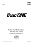
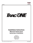
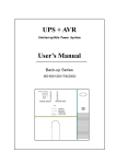
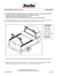
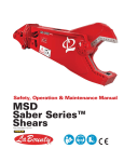
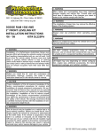
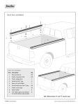
IN-42000_B
TracRac G2
Overhead Rack
Installation Instructions
TracRac Inc.
994 Jefferson St.
FallRiver MA 02721
www.tracrac.com
800-501-1587
TracRac Inc. 994 Jefferson St. Fall River, MA 02721 l 800-501-1578
Instruction Manual
T
hank you for your purchase of a TracRac G2 Sliding Cargo Manaagement System from TracRac®.
TracRac® takes great pride in the quality and workmanship we put into every product. We designed
the TracRac specifically to meet your cargo management needs and it will do just that. With 1250 lbs of
load capacity and its heavy-duty aluminum construction you can be sure this rack can handle all of your
gear.
To get started, please take a minute to reference the Component &Hardware page and ensure that you
have everything nessessary to install your new rack. The installation should take you approximately 65
to 90 minutes.
Required Tools:
TABLE OF CONTENTS:
TracRac G2 Components & Hardware ....
Cleats/Base Assembly ...............................
Saddle Assembly ........................................
Crossbar Assembly .....................................
Cross Bar Assembly ..................................
Tiedown/End Cap Assembly .....................
Truck Installation ........................................
Use & Care ...................................................
Warranty ......................................................
Product Registration ..................................
Page. 2
Page. 3
Page. 4
Page. 5
Page. 6
Page. 7
Page. 8
Page. 9
Page. 10
Page. 11
•
•
•
7/32” Allen Key*
3/16” Allen Key*
Tape Measure
Recommended Tools:
•
•
•
7/32” & 3/16” Hex Bit Socket
1/4” Socket Adaptor & Electric Drill**
Socket Wrench
*An Allen key with a T-handle are best
**Please do not use an impact drill - a typical 1218 volt drill is appropriate
PLEASE READ BELOW - IMPORTANT!
WARRANTY REGISTRATION FORM
•
Please DO NOT FORGET to fill out your Warranty Registration Form on the back of this installation guide or online at www.
tracrac.com. By completing (this form or on tracrac.com) and returning your PRODUCT REGISTRATION FORM you will
receive these important benefits:
WARRANTY CONFIRMATION:
•
Your prompt product registration confirms your right to the protection available under terms and conditions of your TracRac
warranty.
PRODUCT PROTECTION:
•
We will keep the model number and date of purchase of your TracRac product on file to help refer to this information in the event
of a product warranty issue.
Please follow these instructions carefully. Ensure that bolts are torqued to the specified rating and ensure that all diagramed
and instructed relative distances for components are met. Failure to do so will waive the warranty.
Instruction Manual
TracRac Inc. 994 Jefferson St. Fall River, MA 02721 l 800-501-1578
OVERHEAD RACK COMPONENTS
MDP Sliding Base
Qty 2 of Each
MDP Saddle
Qty 4
MDP Upright
Qty 4
Front Right
Rear Left
ARC Side Cleat
Qty 4
Aluminum Crossbar
End Cap - Qty 4
Front Left
Rear Right
MDP Crossbar
Qty 2
OVERHEAD RACK HARDWARE
3/8 - 16 x 1.5”
Flat Head Cap Screw
(FHCS)
Qty - 16
TracKnob
Qty:4
3/8 - 16
Square Nut
Qty - 8
3/8 - 16 x .625”
Button Head Cap
Screw (BHCS)
Qty - 8
MDP Composite Base
Insert
Qty:8
TracRac Inc. 994 Jefferson St. Fall River, MA 02721 l 800-501-1578
1/4-20x 1.75”
Socket Head Cap
Screw (SHCS)
Qty - 8
T-Bolt 3/8 - 16 x
1.125”
Qyt: 4
Aluminum Crossbar
Tiedown
Qty:4
M6-1
Socket Head Cap
Screw (SHCS)
Qty - 4
Tiedown Knob
Qty:4
Instruction Manual
CLEAT ASSEMBLY:
Image A
1. Line the Cleat up over the rivet nut and bolt to the
2.
3.
upright using the 1/4-20x 1.75” Socket Head Cap
Screw (SHCS). See Image A
Torque to 6 ft-lbs. using 3/16 Allen Key.
Repeat for the remaining uprights (4 Total)
BASE ASSEMBLY:
1. Insert the decal-end of the MDP Upright into the MDP Sliding
Image B
Large Loft
Base.
Important Note: Please make sure that the cleats are facing
the larger loft of the base unit. See Image B (To double check,
see Image C on the next page.)
2. Bolt the MDP Sliding Base to the MDP Upright using Two 3/8 - 16 x
Image C
1.5”(FHCS). Making sure the tool is fully inserted into the bolt, tighten
using a 7/32 Allen Key.
Important Note: TracRac has intentionally made the tolerance
between the bolt and the thread tight for maximum performance
- Please hand-thread the bolts for the first few turns to ensure
that proper engagement is achieved. You may also experience
the need for additional force once the pink material engages
the thread. This pink material is an assembly activated Loc-Tite
Small Loft
that will ensure the rack does not need to be retorqued once
installed.
3. Torque FHCS to 32 ft-lbs.
4. Insert the Composite Base Sliders (hole end first) into the MDP Sliding Base until they click into place. 2 Per Base See Image D
5. Repeat for the remaining uprights.
Image D
Instruction Manual
TracRac Inc. 994 Jefferson St. Fall River, MA 02721 l 800-501-1578
SADDLE ASSEMBLY:
1. Insert the non-decal end of the upright in the saddle unit.
2.
3.
Important Note: Please make sure that the small loft is facing the cleat side of the upright. (To double check, place the
slider flat on the floor with the upright standing upwards.
When the saddle is installed correctly the top of the saddle
unit will be parallel to the floor.) See Image A & C
Bolt the MDP Saddle to the MDP Upright using Two 3/8 - 16
x 1.5”(FHCS). Tighten using a 7/32 Allen Key. Please note the
guidelines from Base Assembly Step 2. See Image B
Repeat for the remaining three uprights
Important Note: If you are installing a Cantilever Extension refer to those instructions before assembling all of the
saddles.
Image B
Image A
Large Loft
Small Loft
Image C
TracRac Inc. 994 Jefferson St. Fall River, MA 02721 l 800-501-1578
Instruction Manual
CROSSBAR ASSEMBLY:
1. Pre-Thread the 3/8 - 16 x .625” (8) Button Head Cap Screw (BHCS) and the (8)
2.
3.
4.
5.
Image A
Square Nuts with a ¾ turn and set aside. See Image A
Group together one right/left upright pair, a MDP Crossbar, and 4 of the BHCS/Square
Nut pairs. See Image B
Note: When standing the racks right to left should angle towards one another; and
front to back the elongated end of the sliders should be facing one another.
Take 2 of the BHCS/Square Nuts, with the square nuts facing up and place one into
each of the slots of the MDP Saddle.
Take one of the MDP Crossbars and orientate the bar so that the bottom is facing the
floor. See image C. Holding the bolts in the slots of the saddle slide the square nuts into
the bottom T-Slot of the crossbar. See Image D
Do not tighten the bolts until step 5, repeat on the opposite side and the remaining pair
of uprights.
Image B
Image C
TOP
BOTTOM
Image D
Instruction Manual
TracRac Inc. 994 Jefferson St. Fall River, MA 02721 l 800-501-1578
TIEDOWN & ENDCAP ASSEMBLY:
1. Remove the Aluminum Crossbar Tiedowns from the bubble wrap and locate 4 T-bolts and Tiedown Knobs.
2. Insert the T-bolt through the hole of the tiedown and loosely secure with the knob.
3. Slide the unit into the top track of the crossbar and twist the knob until securely in place.
Image A
4. Next locate the Aluminum Crossbar End Caps. Making sure the flat side of the end cap is facing
towards the ground, insert the end cap into the crossbar and secure using the M6-1 Socket Head
Cap Screw (SHCS). Tighten using a 3/16 Allen Key.
Image B
Image C
Flat Side Down
TracRac Inc. 994 Jefferson St. Fall River, MA 02721 l 800-501-1578
Instruction Manual
TRUCK INSTALLATION:
1. Take one of the two racks (Front Rack –
towards the cab) assemblies and slide the
unit onto the outside track of the base rails.
Take the other rack (Rear Rack – towards
the tailgate) and slide onto the inside track.
Once in place, insert the male knob into the
slider and tighten until the saddle is parallel
to the ground.
Front Rack
Rear Rack
2. Once on the vehicle, starting with two bolts on the inside of the rack, tighten the BHCS securing the
3.
crossbar to the saddles.
Torque BHCS to 27 ft. lbs. using the 7/32 Allen Key.
Note: You will want to make sure that the crossbar is centered on the vehicle. To do this, measure from
the tip of the crossbar to the saddle. Ensure that dimension X is the same on both sides of the crossbars.
Image A
Image B
X
Instruction Manual
TracRac Inc. 994 Jefferson St. Fall River, MA 02721 l 800-501-1578
4. Loosen the male knobs in the slider to ensure that both racks slide smoothly on the base rails.
NOTE: If the racks are not sliding: Double check to make sure your base rails are parallel and square. Check the
sliders and make sure they are centered on the t-tracks of the base rails – if they are hitting the track on one side or
the other, adjust the saddle/crossbar connection to ensure an even disposition of the rack relative to the base rails.
GENERAL USE & CARE:
Please read the following guidelines - it is very important that you follow these instructions to ensure your rack
continues to function properly and to ensure your product remains covered under the TracRac Limited Lifetime
Warranty.
•
•
•
•
•
KNOBS: The knobs on your TracRac are made from stainless steel. To prevent them from seizing up
(especially in the winter), 1-2 times/season, remove all 4 of the TracKnobs from the Sliding Base and
clean any buildup on the threads with a piece of Scotch-Brite™or similar abrasive cloth. After the threads
are clean, spray the threads of the knobs and the threads of the base with WD-40®, Never-Seize type
lubricant or similar anti-seize lubricant. (Common household Vaseline can suffice).
TIEDOWNS: Make sure tiedowns knobs are secured properly before securing any load to the rack.
ELECTRICAL: When mounting lights or other electrical systems to your TracRac, do not use any
component of the system as a ground or to carry an electrical current. Always run 2 wires to the electrical
unit - One positive lead to the switch for power and one ground lead to the frame of the vehicle. Make sure
the power lead has an appropriate size fuse.
LOAD RATING: TracRac G2 is capable of carrying a maximum of 1250 lbs., evenly distributed when
configured with the rear rack mounted on the inner track and both racks at opposite ends of the base rails.
SAFETY: For good performance and safety, periodically check that the base rails remain parallel and
secure. Re-torque all fasteners to the proper specifications after the first 500 miles and every 10,000 miles
thereafter. Lubricate the threaded portion of all knobs every 2000. Carrying heavy loads over rough roads
with excess speed may damage the system. Always properly secure all cargo. Exercise good judgment at
all times.
TracRac Inc. 994 Jefferson St. Fall River, MA 02721 l 800-501-1578
Instruction Manual
TracRac® Limited Lifetime Warranty
TracRac® Limited Lifetime Warranty
TracRac® Incorporated will warranty all TracRac® truck and van racks manufactured by TracRac® Incorporated during the time
that an original retail purchaser owns the product. TracRac® will warranty all other accessories for a period of 2 years from the
date of purchase. This warranty terminates if a purchaser transfers the product to any other person. To activate this warranty, the
original purchaser must complete and return the Product Registration Card included with the product or complete the Warranty
Registration on the TracRac® website at http://www.tracrac.com, to enable TracRac® to verify original ownership.
Subject to the limitations and exclusions described in this warranty, TracRac® will remedy defects in the structural integrity of the
product related to materials or workmanship by repairing or replacing, at its option, a defective product without charge for parts or
labor. In addition, TracRac® may elect, at its option, not to repair or replace a defective product but rather to issue to a purchaser
a refund equal to the purchase price paid for the product or a credit to be used toward the purchase of a new TracRac® product.
No warranty is given for defects caused by shipping damage, normal wear and tear, cosmetic discoloration, scratches or chips,
road hazards, accidents, unlawful vehicle operations, or modification of, or any types of repair of a truck or van rack system other
than those authorized by TracRac®.
No warranty is given for defects resulting from conditions beyondTracRac’s control including, but not limited to, misuse, overloading,
or failure to assemble, install or use the product in accordance with TracRac’s written instructions or guidelines included with the
product or made available to the purchaser.
No warranty is given for TracRac® products purchased outside of the United States, Canada and Mexico.
In the event that a product is defective, the purchaser should contact the TracRac® Customer Service group in writing or by phone
at: 994 Jefferson Street, Fall River, MA 02721 Attn: Customer Service 1 (800) 501 1587
In the event that a product needs to be returned to TracRac®, a TracRac® Customer Service Representative at the address or
telephone number listed above will provide the purchaser with the appropriate mailing address and any additional instructions.
Please note that the purchaser will be responsible for the cost of mailing the product to TracRac® and that proof of purchase in the
form of an original purchase invoice or receipt and a detailed description of the defect must be included in the mailing.
Disclaimer of Liability
Repair or replacement of a defective product or the issuance of a refund or credit (as determined by tracrac) is a purchaser’s
exclusive remedy under this warranty. Damage to a purchaser’s vehicle, cargo and/or to any other person or property is excluded.
This warranty is expressly made in lieu of any and all other warranties, express or implied, including the warranties of merchantability
and fitness for a particular purpose. Tracrac’s sole liability to any purchaser is limited to the remedy set forth above. In no event
will tracrac be liable for any lost profits, lost sales, or for any consequential, direct, indirect, incidental, special, exemplary, or
punitive damages or for any other damages of any kind or nature. Some states do not allow the exclusion or limitation of incidental
or consequential damages, so the above limitations may not be applicable. This warranty gives you specific legal rights, and you
may also have other rights, which may vary from state to state.
WARRANTY REGISTRATION FORM
By completing (the form on the next page or on tracrac.com) and returning your PRODUCT REGISTRATION FORM you will receive
these important benefits:
WARRANTY CONFIRMATION:
Your prompt product registration confirms your right to the protection available under terms and conditions of your TracRac
warranty.
PRODUCT PROTECTION:
We will keep the model number and date of purchase of your TracRac product on file to help refer to this information in the event of
a product warranty issue.
Instruction Manual
TracRac Inc. 994 Jefferson St. Fall River, MA 02721 l 800-501-1578