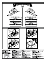
1
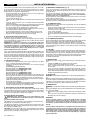
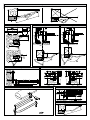
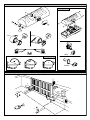
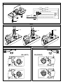
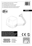
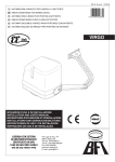
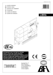
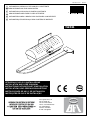
D811296 ver. 07
30/07/07
I AUTOMAZIONI A BRACCIO PER CANCELLI A BATTENTE
GB ARM AUTOMATIONS FOR SWING GATES
F AUTOMATIONS A BRAS POUR PORTAILS BATTANTS
D ARM AUTOMATIONEN FUER FLUGELGITTERTIRE
8
027908 1 7 1 9 9 3
E AUTOMATIZACIONES A BRAZO PARA PORTONES CON BATIENTE
P AUTOMATIZAÇÕES DE BRAÇO PARA PORTÕES DE BATENTE
IGEA
ISTRUZIONI D’USO E DI INSTALLAZIONE
INSTALLATION AND USER’S MANUAL
INSTRUCTIONS D’UTILISATION ET D’INSTALLATION
INSTALLATIONS-UND GEBRAUCHSANLEITUNG
INSTRUCCIONES DE USO Y DE INSTALACION
INSTRUÇÕES DE USO E DE INSTALAÇÃO
Via Lago di Vico, 44
36015 Schio (VI)
Tel.naz. 0445 696511
Tel.int. +39 0445 696533
Fax 0445 696522
Internet: www.bft.it
E-mail: [email protected]
D811296_07
INSTALLATION MANUAL
ENGLISH
Thank you for buying this product. Our company is sure that you will be more
than satisfied with the product’s performance.
Carefully read the “WARNINGS” pamphlet and the “INSTRUCTION BOOKLET” which are supplied together with this product, since they provide
important information regarding the safety, installation, use and maintenance
of the product. This product complies with recognised technical standards
and safety regulations. We declare that this product is in conformity with the
following European Directives: 73/23/ EEC, 89/336/EEC, 98/37/EEC and
subsequent amendments.
WARNING! The installation, the maintenance and the repair should be
done by responsible and qualified persons with an updated knowledge of
the current safety standards. It’s strictly forbidden to service the automation
when the power is on.
ATTENTION! The IGEA model controller is not equipped with mechanical
torque adjustment. It is compulsory to use a control panel of the same manufacturer, in compliance with the basic safety requirements of directives
73/23/CEE, 89/336/CEE, 89/37/CEE equipped with appropriate electric
adjusment of the torque.
1) GENERAL SAFETY
WARNING! An incorrect installation or improper use of the product
can cause damage to persons, animals or things.
• The “Warnings” leaflet and “Instruction booklet” supplied with this
product should be read carefully as they provide important information
about safety, installation, use and maintenance.
• Scrap packing materials (plastic, cardboard, polystyrene etc) according
to the provisions set out by current standards. Keep nylon or polystyrene
bags out of children’s reach.
• Keep the instructions together with the technical brochure for future
reference.
• This product was exclusively designed and manufactured for the use
specified in the present documentation. Any other use not specified in
this documentation could damage the product and be dangerous.
• The Company declines all responsibility for any consequences resulting
from improper use of the product, or use which is different from that
expected and specified in the present documentation.
• Do not install the product in explosive atmosphere.
• The construction components of this product must comply with the
following European Directives: 89/336/CEE, 73/23/EEC, 98/37/EEC
and subsequent amendments. As for all non-EEC countries, the abovementioned standards as well as the current national standards should
be respected in order to achieve a good safety level.
• The Company declines all responsibility for any consequences resulting
from failure to observe Good Technical Practice when constructing closing
structures (door, gates etc.), as well as from any deformation which might
occur during use.
• The installation must comply with the provisions set out by the following
European Directives: 89/336/CEE, 73/23/EEC, 98/37/EEC and subsequent amendments.
• Disconnect the electrical power supply before carrying out any work on
the installation. Also disconnect any buffer batteries, if fitted.
• Fit an omnipolar or magnetothermal switch on the mains power supply,
having a contact opening distance equal to or greater than 3,5 mm.
• Check that a differential switch with a 0.03A threshold is fitted just before
the power supply mains.
• Check that earthing is carried out correctly: connect all metal parts for
closure (doors, gates etc.) and all system components provided with an
earth terminal.
• Fit all the safety devices (photocells, electric edges etc.) which are needed
to protect the area from any danger caused by squashing, conveying and
shearing, according to and in compliance with the applicable directives
and technical standards.
• Position at least one luminous signal indication device (blinker) where it
can be easily seen, and fix a Warning sign to the structure.
• The Company declines all responsibility with respect to the automation
safety and correct operation when other manufacturers’ components are
used.
• Only use original parts for any maintenance or repair operation.
• Do not modify the automation components, unless explicitly authorised
by the company.
• Instruct the product user about the control systems provided and the
manual opening operation in case of emergency.
• Do not allow persons or children to remain in the automation operation
area.
• Keep radio control or other control devices out of children’s reach, in
order to avoid unintentional automation activation.
• The user must avoid any attempt to carry out work or repair on the
automation system, and always request the assistance of qualified
personnel.
• Anything which is not expressly provided for in the present instructions,
is not allowed.
• Installation must be carried out using the safety devices and controls
prescribed by the EN 12978 Standard.
3) TECHNICAL SPECIFICATIONS
Voltage:.......................................................................230V~ ±10% 50Hz (*)
Motor:......................................................................Single-phase 1400min-1
Power:.................................................................................................. 300W
Absorption:........................................................... 1.7A (230V); 3,4A (110V)
Capacitor:.........................................10µF 450V (230V); 40µF 250V (110V)
Insulation class:.......................................................................................... F
Thermal protection:........................................................130°C self-resetting
Lubrication:...................................................................... Permanent grease
Reduction ratio:.................................................................................... 1/812
Output revs.:............................................................................ 1.7 min-1 max
Opening time 90°:....................................................................................15s
Torque provided:................................................................320Nm (~32kgm)
Max. leaf weight and length:................2000N (~200kg) for 2.5m leaf length
2500N (~250kg) for 2m leaf length
Impact reaction:.......................................Electric clutch (with control panel)
Drive:............................................................................................ Lever arm
Stopping:.........................................................Built-in electric limit-switches
Manual manoeuvre: ............................Release knob with personalised key.
Number of manoeuvres:.................................................................. 100/24h
Working temperature:.......................................................... -15 C° ÷ +60 C°
Protection:............................................................................................ IP 44
Controller weight:.....................................................................160N (~16kg)
Dimensions:.................................................................................... See fig.1
* Special supply voltages on request.
In case the motor tours in the opposite side, you should invert the running
buckle “M” of the operator. Refer to the relevant instruction manual for connection of the control panel.
2) GENERAL OUTLINE
This controller is suitable for residential use and has been designed for swing
gates with particularly large gate posts. The drive arm, built with a special
anti-shearing shape, allows the leaves to be moved when the controller
is considerably out of place with respect to the fulcrum of the leaves. The
non-reversible electro-mechanical gearmotor maintains the stop during
closing and opening.
The release knob with personalised key, fitted outside each operator, makes
manual manoeuvre extremely easy.
4) OPERATOR INSTALLATION
WARNING! Refer to Fig.A for CORRECT installation.
4.1) Preliminary checks
Check that:
• The gate structure is sufficiently sturdy and rigid.
The fixing position must be worked out according to the leaf structure.
In any case, the manoeuvring arm must push against a reinforced leaf
point (fig. 2).
• The leaves can be moved manually along their entire stroke.
If the gate has not been installed recently, check the wear condition of
all its components. Repair or replace defective and worn parts.
Operator reliability and safety are directly affected by the condition of the
gate structure.
4.2) Fitting of the manual release knob
• With reference to fig. 9, position release knob “A” on flange “B” prefitted
on the cover.
• Insert adapting ring “C” in the bush with release tooth “D”.
WARNING: Depending on the operator installation position (right or
left side), insert ring “C” and position bush “D” as shown in fig. 9.
• Insert space washer “E” and then shimming thrust bearing “F” into bush
”D” on the release tooth side.
• Secure everything, using appropriate self-tapping screw “G” inside the
operator cover, checking the correct positioning of ring “C” and bush “D”.
• Close the operator cover, using the appropriate screws supplied.
WARNING: The release tooth on bush “D” must be inserted in the
release lever as shown in fig. 9b. Otherwise, the emergency manoeuvre cannot be carried out.
Insertion is made easy by turning knob “A” to the side opposite to that for
manual release (clockwise in the case of a left-hand leaf, anticlockwise
in the case of a right-hand leaf) and locking it in such position by means
of the appropriate key.
Check that bush “D” is placed horizontally (fig. 9b) and close the cover by
positioning its front side (the one with the release knob) as indicated in fig. 9c.
• Before connecting the operator to the power supply, manually check that
the release knob operates correctly.
5) FIXING OF SUPPORTING PLATE (Fig.2)
The controller is supplied complete with anchoring bracket and lever arm.
Once the reinforcement point of the leaf has been identified with the gate
closed, draw an imaginary horizontal line from the centre of the reinforcement
point to the gate post (fig.2). Position the anchoring bracket according to the
values given in fig. 2 for openings of up to 90° or in fig.3 for openings greater
than 90° up to a maximum of 125°.
IGEA Ver. 07 - 11
INSTALLATION MANUAL
The bracket fixing position must be flat and parallel to the leaf. Use screws
or expansion bolts which are suited to the type of gate post. If the surface
of the gate post is not regular, use expansion bolts with studs so that the
parallel plate of the leaf can be adjusted (fig.4).
• Fasten the gearmotor to the gate post using the 4 screws, pointing the
gearmotor to the left or the right (fig.5).
• Assemble the lever arm as shown in fig.6.
DX= assembly on the right leaf
SX= assemby on the left leaf
Choose the most suitable position of ‘F’ bracket for the fastening to the
leaf.
• Insert the square of the first lever in the output shaft of the gearmotor
and fasten it (fig.7).
• Release the operator by turning the release knob to allow easy movement
of the arm (see paragraph on “EMERGENCY MANOEUVRE”).
• The correct position for the controller arm is shown in fig.8.
The leaf fixing point can be identified by positioning the arm so that it is
in accordance with the distance shown in fig.8.
• Fix the angular towing bar “F” to the leaf by welding or using screws.
• With the controller released, check the correct movement of the arm.
• Repeat the same operation for the other leaf, if installed.
6) ELECTRICAL INSTALLATION SET-UP
Arrange the electrical installation as shown in fig.10.
The power supply connections must be kept separate from the auxiliary
connections (photocells, sensitive edge, etc.). Fig.10 shows the cross-section
and the number of connections.
WARNING! For connection to the mains, use a multipolar cable with a
minimum of 4x1.5mm2 cross section and complying with the previously mentioned regulations. For example, if the cable is out side (in the
open), it has to be at least equal to H07RN-F, but if it is on the inside
(or outside but placed in a plastic cable cannel) it has to be or at least
egual to H05VV-F with section 4x1.5mm2.
In fig.11 you will find the junction-box of the operator and the position of the
cable holder which should be fixed with an adequate tightening of the bolt.
In case the motor tours in the opposite side, you should invert the running
buckle “M” of the operator. Refer to the relevant instruction manual for connection of the control panel. Inside the operator the cable must be kept far
from those parts which can be hot.
7) LIMIT-SWITCH SETTING
• Position the limit-switch reference cams “R-FC1” and “R-FC2” as shown
in fig. 12, without tightening the fixing screws.
• Identify the opening and closing limit switches (FC1 and FC2) keeping
in mind that:
In the left-hand operator (fig. 13):
FC1 corresponds to the OPENING limit switch
FC2 corresponds to the CLOSING limit switch
In the right-hand operator (fig. 14):
FC1 corresponds to the CLOSING limit switch
FC2 corresponds to the OPENING limit switch
• When the gate is fully closed or opened, rotate the corresponding cam
until you perceive the click of the limit microswitch concerned, and lock
it in position by tightening the appropriate screws as shown in fig. 12.
• Check that the limit switches intervene correctly, initiating a few complete
motor-driven opening and closing cycles.
• Fit the cover on the operator.
• f the control panel is provided with operation-time setting, this must be set
to a value slightly greater than that needed for limit-switch intervention.
• Control the operator through the control board Libra.
8) ADJUSTMENT OF LEAF PHASE DISPLACEMENT
In case of gates with two leaves, the control panel should include a delay
setting function on closing of the second leaf to guarantee a correct closing
manoeuvre. For the wiring of the motor which should close with a slight delay,
refer to the instructions for the control panel installed.
9) MOTOR TORQUE ADJUSTMENT
WARNING: Check that the impact force value measured at the
points established by the EN 12445 standard is lower than that
specified in the EN 12453 standard.
The adjustment of the motor torque (anti-squashing) is performed on the
control panel. See control unit instruction manual.
The adjustment should be set for the minimum force required to carry out
the opening and closing strokes completely observing, however, the limits
of the relevant standards in force.
CAUTION! Excessive torque adjustment may jeopardise the anti-squash
safety function. On the other hand insufficient torque adjustment may not
guarantee correct opening or closing strokes.
12 - IGEA Ver. 07
10) EMERGENCY MANOEUVRE (Fig. 15)
In the case of power failure or operation malfunctions, manual emergency
manoeuvre can be carried out by turning the external release knob with
personalised key.
First turn the key clockwise, then rotate the release knob to free the gate.
The knob is to be rotated anticlockwise in the case of a left-hand leaf,
clockwise in the case of a right-hand leaf.
Keep the knob in its release position by turning the key further. Push the leaf
slowly to open or close the gate.
To reactivate motor-driven operation, free the knob from its release position
and bring it back to its initial position for normal operation.
11) AUTOMATION CHECK
Before allowing the automation to be used normally, carry out the following
procedure very carefully:
• Check the correct functioning of all safety devices (limit microswitches,
photocells, sensitive edges etc.).
• Check that the thrust (anti-squash) force of the leaf is within the limits
set by current regulations.
• Check the manual opening command.
• Check the opening and closing operations with the control devices in
use.
• Check the standard and customised electronic functioning logic.
12) AUTOMATION OPERATION
Since the automation can be remote-controlled by means of a remote control
device or a start button, and so out of sight, the good working order
of all the safety devices should be checked regularly. In the event of any
anomalous functioning of the safety devices, consult a specialised technician immediately. Keep children at a safe distance from the automation
operation area.
13) CONTROL
The automation is used for the power-operated opening and closing of the
gate. The control can be of a number of types (manual, remote-controlled,
magnetic badge access control, etc.) depending on requirements and the
characteristics of the installation. See the specific instructions for the various
control systems. Users of the automation must be instructed about
its control and operation.
14) MAINTENANCE
Disconnect the power supply when carrying out any maintenance operations.
• Lubricate the IGEAs of the manoeuvring arm regularly.
• Clean the lenses of the photocells every so often.
• Have a specialised technician (installer) check the adjustment of the
electric clutch.
• In the event of any anomalous functioning which cannot be resolved,
disconnect the power supply and contact a specialised technician (installer). Whilst the automation is out of order, activate the manual release
to allow manual opening and closing.
15) SCRAPPING
WARNING! This operation should only be carried out by qualified personnel.
Materials must be disposed of in conformity with the current regulations.
In case of scrapping, the automation devices do not entail any particular risks
or danger. In case of materials to be recycled, these should be sorted out by
type (electrical components, copper, aluminium, plastic etc.).
16) DISMANTLING
WARNING! This operation should only be carried out by qualified personnel.
When the automation system is disassembled to be reassembled on another
site, proceed as follows:
• Disconnect the power supply and the entire external electrical installation.
• In the case where some of the components cannot be removed or are
damaged, they must be replaced.
WARNINGS
Correct controller operation is only ensured when the data contained
in the present manual are observed. The company is not to be held
responsible for any damage resulting from failure to observe the
installation standards and the instructions contained in the present
manual.
The descriptions and illustrations contained in the present manual are
not binding. The Company reserves the right to make any alterations
deemed appropriate for the technical, manufacturing and commercial
improvement of the product, while leaving the essential product features unchanged, at any time and without undertaking to update the
present publication.
D811296_07
ENGLISH
CORRETTO / RIGHT / JUSTE / RICHTIG / CORRECTO / JUSTO:
NON CORRETTO / WRONG / FAUX / FALSCH / NO CORRECTO / ERRADO:
Fig. 1
Fig. 2
146
Fig. 3
170
20
110
165
315 MIN
165
315 MIN
93˚
SX
220
SX
360
170
MAX 300
110
600
300
MAX
D811296_07
Fig. A
170
700
180˚
Fig. 4
Fig. 5
Sinistra / Left
Gauche / Linke
Izquierdo / Esquerda
Fig. 6
Destra / Right
Droite / Rechts
Derecha / Direita
Fig. 7
S
F
De
ita
ire
/D
/D
R
e/
t
roi
t/D
gh
/Ri
a
str
hts
ec
a
ch
ere
ra
st
ini
eft
/L
e
ch
au
/L
in
/
ke
rdo
uie
Izq
/
Fig. 8
rda
ue
q
Es
S
/G
S
5
S
101
S
IGEA Ver. 07 - 21
D811296_07
Fig. 9
Fig. 9b
D
C
A
B
D
G
F
E
D
C
RIGHT
LEFT
D
D
C
C
LEFT
RIGHT
LEFT
D
Fig. 9c
1
2
3
RIGHT
D
Fig. 10
AL
M
S
Fre
2
2
m
1m
2x Fti
m
.5m 2
4x1 1mm
x
4
3x1m
m2
RG5
2x1.5 8 2
mm
Fte
QR
2x1.5
CF
mm2
I
M
2
.5m
4x1
T
2
mm
Fri
4x1
CF
22 - IGEA Ver. 07
m
3x1.5
mm2
D811296_07
Fig. 11
F1
F2
3
1 2
F1
F2
GND
L
M
230V
CM
N
M
1
2
F2-NC
F2-COM
F1-NC
F1-COM
NERO-BLACK-NOIR-SCHWARZ-NEGRO-PRETO
M
MARRONE-BROWN-MARRON-BRAUN-MARON-CASTANHO
CELESTE-SKY-BLUE-BLEU CLAIR-HELLBLAU-AZUL-CELESTE
3
PG11
Fig. 12
R - FC2
R - FC1
R - FC2
R - FC1
FC1
FC2
FC1
FC1
FC2
FC2
Fig. 13
Fig. 14
LEFT
SX (LEFT)
DX (RIGHT)
RIGHT
OPEN SX FC1
CLOSE DX FC1
CLOSE SX FC2
OPEN DX FC2
IGEA Ver. 07 - 23
Fig. 15
LEFT
RIGHT
1
1
2
2
3
3
Fig. 16
D
ø 5 mm