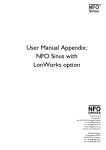
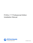
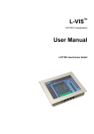
1
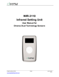
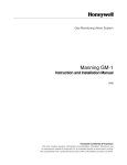
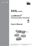
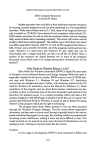
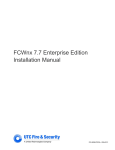
Networking Node for Relay Scanner
Technical Data
WNX-2624
PART No.
DESCRIPTION
SPECIFICATION
WNX-2624
Network Node
The WNX-2624 Network Node permits
Douglas WRS-2224 Relay Scanners to
be networked together.
The WNX-2624 Node uses state-of-theart LonWorks® networking technology
and is LonMark® certified (3.1).
WNX-2624 nodes can be networked in
one of 2 methods.
1) Self-configured network (default)
2) Externally configured network
Self-Configured Networks
Self-configured networks are ideal for
expanding the number of relay outputs
controlled by a scanner switch input.
When networked, the switch input of a
scanner has global reach and can
control any quantity of relay outputs
throughout the system.
Externally Configured Networks
Other control systems that use LonWorks
technology can digitally integrate the
WNX-2624 as a part of that system. This
requries that the other system has the
necessary features, software and interface
for lighting control.
The WNX-2624 node is LonMark certified,
and will accept all the LonWorks
commands relevent for lighting control.
Power
n
The WNX-2624 network node obtains
power from the host WRS-2224 relay
scanner. CAUTION: Always disconnect
24VAC from the scanner prior to
plugging/unplugging the WNX-2624 unit.
n
n
■
Wire Type & Method
Nodes are connected together with a 2wire cable. Use 16 AWG, twisted pair,
unshielded cable. Stranded or solid
conductor.
Refer to "INSTALLATION - LonWorks
Data Signal Wiring" for more details.
Free topology network wiring is supported.
Data signal can be wired with branches
and tees. Overall network wire length
should not exceed 1650 feet (500m).
Longer data signal lengths are possible if
devices are connected in a serial bus.
Optionally a repeater can be used to
increase data signal length.
Connections are not polarity sensitive.
n
n
n
n
n
n
n
n
Network Operation & Size
Simple basic networks are self-configured
and up to 24 nodes can exist in a system
(WNX-2624 and WNS-2308 nodes).
The WNX-2624 and WNS-2308 nodes
can also be integrated into other systems
that use the LonWorks technology.
n
n
n
Individual Output
Buttons
Relay Outputs
Networking Technology Specification
In operating mode, use
buttons to switch the
connected relay ON or OFF.
In programming mode, use
buttons to enter or remove
the relay from the input
being programmed.
24 output terminals (12 per
side), are provided for relay
control.
Douglas 2-wire switches can
be connected in parallel to
permit individual control of a
relay by switch.
Select Buttons
& LED's for:
n
Environment
n
Override Buttons
n
Use ON and OFF
override buttons to
switch relay groups.
1) Operating mode
2) Program mode
3) Flick Warn before OFF Option
Relay Group Select
Use the relay group select
button to choose the relay
group input 1,2,3,4 or 5.
The selected input will
have its led ON.
Directions
Directions are printed on
keypad for handy user
reference.
Controls on WNX-2624 are
used for reviewing node
address and switch codes.
LonWorks® technology
LonMark® Certified (V3.1).
Network signal:
FTT-10 Transceiver.
n
Environment: Indoors, stationary, nonvibrating, non-corrosive atmosphere and
non-condensing humidity.
Ambient temp: +15°to +120°F (-10° to +50°C)
DIMENSIONS & MOUNTING
n
n
Be sure to disconnect 24VAC from relay
scanner before plugging/unplugging
network node into scanner.
Mount node to 35mm DIN rail installed
in Douglas relay panel.
Side
Plan View
6.5"
(165)
1
2
3
4
5
6
7
8
9
10
11
12
View
1
13
14
15
16
17
18
19
20
21
22
23
24
W
B
13
2
14
4
16
6
18
8
20
10
22
12
24
3
15
5
17
7
19
9
21
11
23
ON
OVERRIDE
WRS-2224
Relay
Scanner Sw
OFF
OVERRIDE
SELECT
MASTER
SWITCH
1
2
3
B
Inputs 4
5
B
LOOK-UP BUTTONS
(Self-configured networks only)
FTT-10 transceivers are
used to communicate the
LonWorks protocol.
Data signal cable is
#16AWG, twisted pair,
Interfaces 3.1
C-3-1,2,3,4 -Systems, LonWorks Products
www.DouglasLightingControls.com
NODE ADDRESS
2.5"
(64)
SWITCH CODE
WNX-2624
Network Node
SERVICE &
ERASE
NET MANAGER SELECT
Networks without a scheduler
or computer have to be
self-configured networks.
Choose one node to be the
network manager with this
switch.
LON WORKS
NETWORK SIGNAL
(FTT-10A Transceiver,
non-polarized, 78Kbps)
B
Data Signal
A
w www.DouglasLightingControls.com
m
o
c
.
s
l
r
t
o
C
g
n
i
t
h
I
L
s
a
l
g
u
o
D
.
ON
OFF
4.0"
(103)
L o n M a rk
C e r t if i e d
1.75"
(45)
Networking Node with 8 Inputs
Technical Data
WNS-2308
PART No.
DESCRIPTION
SPECIFICATION
WNS-2308
Eight Input Node
The WNS-2308 Input Node provides
EIGHT inputs that can control any group
of relays in a Douglas system using
networked WRS-2224 scanners.
The inputs of the WNS-2308 can each be
configured to be compatible with a variety
of hardware types and can be configured
to operate in a specific manner. The
default configuration is: Douglas 2wire
relay switch operating in the ON/OFF
mode. Please refer to the table below for
the complete list of hardware types and
switch modes available.
The WNS-2308 uses state-of-the-art
LonWorks® networking technology and
LonMark certified control objects for
lighting control.
The WNS-2308 Input Node can be
used in one of 2 methods:
1) Self configured Network (default)
2) Externally configured Network
Self-Configured Networks
Use in a self cofigured network to add
inputs.
Externally configured networks
Other controls systems that use
LonWorks technology can digitally
integrate the WNS-2308 as a part of
the other system.
Power
n
24VAC, 100mA
n
Wire Type & Method
n
Nodes are connected together with a 2wire cable. Use 16 AWG, twisted pair,
unshielded cable. Stranded or solid
conductor.
Refer to "INSTALLATION - LonWorks
Data Signal Wiring" for more details.
Free topology network wiring is supported.
The data signal can be wired with tees and
branches. Overall network wire length
should not exceed 1650 feet (500m).
Longer data signal lengths are possible if
devices are connected in a serial bus.
Optionally, a repeater can be used to
increase data signal length.
Connections are not polarity sensitive.
n
n
n
n
n
n
n
Network Operation & Size
Simple basic networks are self-configured
and up to 24 nodes can exist in a system.
(WNX-2624 and WNS-2308 nodes).
The WNX-2624 and WNS-2308 nodes
can also be integrated into larger systems
that use the LonWorks technology.
n
n
n
n
Networking Technology Specification
LonWorks® technology
LonMark® Compliant
Network signal:
FTT-10 Transceiver.
n
Hardware & Switching Mode Options
The table below is printed on the
membrane key pad for easy reference.
(The WNS-2308 is shown with the peelaway description label applied)
Below is a reprint of the table to show the
different hardware types and switching
modes available from the keypad of the
WNS-2308.
In many cases, other systems are
integrated with a contact closure. Use the
table to determine the appropriate
hardware type for the control supplied.
Sw Mode
A C M o m O N
O N O n ly
A C M o m O F F
F lic k
A C N C = O N , N O = O F F
T im e O u t
A C N C = O F F , N O = O N
D e la y O F F
n
Master Switch
Override Buttons
Use input buttons A
to H to switch inputs
ON/OFF.
Led's show status of
relay group
assigned to the
input.
D e la y O N
A C N C = N o n e , N O = O F F
H o u s e k e e p in g O N
D o u g la s 2 w ir e S w itc h
D C P o s = O F F , N e g = O N
W in k ( S e n tr y )
D C P o s = O N , N e g = O F F
R e g u la r O N /O F F
D C N o S ta tu s S ig n a l
R e d o O N /O F F
D is a b le d
Hardware Type
Interfaces 3.2
C-3-1,2,3,4 -Systems, LonWorks Products
n
DIMENSIONS & MOUNTING
The WNS-2308 mounts to 35mm DIN rail
in Douglas relay panel.
Basic programming
directions are printed
on keypad for handy
user reference.
Detailed directions for
specialized settings
are in user manual.
Select Buttons
& LEDs for:
1) Program mode
2) Hardware options
3) Input switching mode settings
including the flick warn option.
4) Input # and unit ID settings
Side
View
Plan View
WNS-2308
Network Node with
8 Inputs
Directions
A C N C = O F F , N O = N o n e
A C N C = N o n e , N O = O N
Environment: Indoors, stationary, nonvibrating, non-corrosive atmosphere and
non-condensing humidity.
Ambient temp: +15° to +120°F (-15° to +50°C)
n
A C N C = O N , N O = N o n e
D e la y O F F & F lic k
Sw Mode
Environment
Hardware Type
O F F o n ly
T im e O u t & F lic k
n
INPUTS
A
B
C
D
6.5"
(165)
E
F
G
H
B
W
B
FLICK
PGM
NODE
ID
INPUT
CODE
Data
Signal
A B cg
Data Signal
FTT-10 transceivers are
used to communicate the
LonWorks protocol.
Wiring is simple 16AWG
twisted pair, unshielded
wire, stranded or solid.
www.DouglasLightingControls.com
4.0"
(103)
1.75"
(45)
Douglas LonWorks Products
Technical Data
CONNECTIONS
Relay Panel
Douglas relays and switches can be easiliy networked by using
relay scanners equipped with network nodes. Local switches and
sensors are still connected directly to relays and system wide
switches/timers are connected to the inputs of the scanner/node
combination.
For system wide control of relays, connect a standard Douglas 2wire switch and/or timer output to a scanner input. By using the
membrane buttons built into the scanners, the relays controlled by
an input are easily selected or de-selected.
Each input of a scanner is unique. That is, input 1 of scanner 1
can be set to control relays connected to scanners 1,2,3 etc.
Input 1 of scanner 2 can be set to control a different group of
relays that are connected to scanners 1,2,3 etc.
By attaching a WNX-2624 network node to a WRS-2224 relay
scanner, a simple, self-managed network can be established.
The WNX-2624 nodes are connected together with a nonpolarized data signal that can be connected to the devices in
either way.
Total data signal length should not exceed 1650 feet (500m). If
longer lengths are required (to a maximum of 7000 ft./2700m),
wire the data signal from node-to-node in sequence (no tees or
branches) or use a repeater.
The WNX-2624 Scanner Node is LonMark certified to ensure
reliable, predictable operation with other control systems that
integrate Douglas relay panels as a part of their system.
n
Lights
Relays
S w
R
R
Scanner/Node
Combination
R
R
1
2
3
4
5
6
7
8
9
10
11
12
R
R
FLICK
WARN
OPTION
R
1
14
15
4
16
6
18
8
20
10
22
12
24
5
17
7
19
21
9
11
PROGRAM
MODE
23
NORMAL
MODE
Floor or Building
Master switches
OFF
OVERRIDE
S w
SELECT
MASTER
SWITCH
1
2
3
B
Inputs 4
5
B
R
R
Time clocks
LOOK-UP BUTTONS
(Self-configured networks only)
NODE ADDRESS
R
Node
SWITCH CODE
WNX-2624
Networks without a scheduler
or computer have to be
self-configured networks.
Choose one node to be the
network manager with this
switch.
S w
n
LON WORKS
NETWORK SIGNAL
(FTT-10A Transceiver,
non-polarized, 78Kbps)
B
R
NET MANAGER SELECT
A
Network Node
SERVICE &
ERASE
n
ON
OVERRIDE
WRS-2224
Relay
Scanner Sw
R
n
S w
Scanner
13
14
15
16
17
18
19
20
21
22
23
24
W
B
13
2
3
Individual
Relay
Switches &
Sensors
ON
OFF
L o n M a rk
C e r t if ie d
n
Data Signal
#16 AWG, twisted pair, no shield
Self-managed systems
of up to 24 nodes can exist
14
4
16
6
18
8
20
22
15
5
17
7
19
9
21
PROGRAM
MODE
23
12
24
NORMAL
MODE
FLICK
WARN
OPTION
ON
OVERRIDE
WRS-2224
Relay
Scanner Sw
2
14
4
16
6
18
8
20
10
22
3
15
5
17
7
19
9
21
11
PROGRAM
MODE
23
12
24
NORMAL
MODE
LOOK-UP BUTTONS
1
2
14
4
16
6
18
8
20
10
22
3
15
5
17
7
19
9
21
11
PROGRAM
MODE
23
12
24
NORMAL
MODE
NODE ADDRESS
Network Node
B
A
(FTT-10A Transceiver,
non-polarized, 78Kbps)
SERVICE &
ERASE
L o n M a rk
C e r tif ie d
OFF
NET MANAGER SELECT
Networks without a scheduler
or computer have to be
self-configured networks.
Choose one node to be the
network manager with this
switch.
OFF
OVERRIDE
SELECT
MASTER
SWITCH
1
2
3
B
Inputs 4
5
B
Simple, Self-configured Networks
LOOK-UP BUTTONS
(Self-configured networks only)
SWITCH CODE
NODE ADDRESS
WNX-2624
LON WORKS
NETWORK SIGNAL
APPLICATION
ON
OVERRIDE
WRS-2224
Relay
Scanner Sw
OFF
OVERRIDE
(Self-configured networks only)
SWITCH CODE
ON
13
14
15
16
17
18
19
20
21
22
23
24
W
B
13
LOOK-UP BUTTONS
(Self-configured networks only)
NODE ADDRESS
Network Node
NET MANAGER SELECT
ON
OVERRIDE
1
2
3
B
Inputs 4
5
B
WNX-2624
Networks without a scheduler
or computer have to be
self-configured networks.
Choose one node to be the
network manager with this
switch.
FLICK
WARN
OPTION
SELECT
MASTER
SWITCH
1
2
3
B
Inputs 4
5
B
SERVICE &
ERASE
1
2
3
4
5
6
7
8
9
10
11
12
13
14
15
16
17
18
19
20
21
22
23
24
W
B
13
WRS-2224
Relay
Scanner Sw
OFF
OVERRIDE
SELECT
MASTER
SWITCH
WNT
2999
n
1
SWITCH CODE
WNX-2624
Network Node
LON WORKS
NETWORK SIGNAL
(FTT-10A Transceiver,
non-polarized, 78Kbps)
SERVICE &
ERASE
ON
L o n M a rk
C e r tif ie d
OFF
NET MANAGER SELECT
Networks without a scheduler
or computer have to be
self-configured networks.
Choose one node to be the
network manager with this
switch.
LON WORKS
NETWORK SIGNAL
A self configured network only requires the network nodes to be
plugged into the relay scanners and connected together via data
signal. For one of the network nodes, set the network manager
switch to "ON" and ensure that the rest of the switches are OFF.
The node with the switch set to ON performs the network
manager functions of configuration and address assignment.
Use the membrane key pads built into the scanners to set which
relays are controlled by an input. Any relay output that is part of
the network can be programmed to an input.
Each relay scanner has 5 inputs and 24 relay outputs. If additional
inputs are required at a location, use the WNS-2308 EIGHT Input
Networking Node.
A self-configured system can support up to 24 nodes. This
provides over 500 relay outputs and 120 inputs.
The flick warn and time out options supported by a stand-alone
WRS-2224 Relay Scanner are also supported on the selfconfigured network. If the input has an option selected with the
keypad of the WRS-2224, the system wide relay group will have the
same feature. The WNS-2308 also supports the flick warn feature.
The WNS-2308 unit has additional features that allow the inputs to
accept control from devices that do not use the Douglas 2wire
switching method. Contact closures of maintained or momentary
nature are easily interfaced to the WNS-2308.
(FTT-10A Transceiver,
non-polarized, 78Kbps)
n
B
2
10
3
11
1
2
3
4
5
6
7
8
9
10
11
12
13
14
15
16
17
18
19
20
21
22
23
24
W
B
13
A
FLICK
WARN
OPTION
1
B
1
2
3
4
5
6
7
8
9
10
11
12
A
Data Signal
Terminator
- Optional
- Install near
center of
data signal
ON
OFF
L o n M a rk
C e r tif ie d
Input Nodes
Used for simple hardwired
connections to networked inputs
WNS-2308
Network Node with
8 Inputs
n
WNS-2308
Network Node with
8 Inputs
WTP-4408
INPUTS
INPUTS
A
A
B
B
C
D
Esc
H
B
W
B
PGM
N OD E
ID
B
1
G
FLIC K
WTP4408
A
E
F
INPUT
CO DE
Data
Signal
A B cg
C
2
1
4
5
2
3
4
7
5
8
6
9
7 08
9
Sensor
Sensor
0
C
D
D
E
3
6
F
G
Clr
W
B
1
2
3
4
5
6
7
8
H
B
W
B
FLIC K
PGM
N OD E
ID
INPUT
CO DE
Data
Signal
Building
Automation
Contact
Interfaces
A B cg
n
n
n
Telephone Interface
Dial-in to actuate any of the
256 relay groups ON or OFF.
n
Data
Signal
WTI-2331
A B cg
Optional Integrated Systems
Douglas LonWorks products are compliant to LonMark standards.
Larger systems that use LonWorks technology can integrate Douglas
relay panels as a part of the larger system. The PC computer and
integration process is performed by the suppliers of integrated systems.
Interfaces 3.3
C-3-1,2,3,4 -Systems, LonWorks Products
n
Externally Configured Networks
Douglas LonWorks based products can be configured and
controlled by an external host system that uses the LonWorks
standards. For programming and operating details of such
systems, please refer to the documentation of the host system.
www.DouglasLightingControls.com
Technical Data
Douglas LonWorks Products
APPLICATION (continued)
INSTALLATION
Integrated Systems
System ID's and Configuration
The nodes used in either self-configured or integrated systems
each have a unique ID. Self-configured systems use the facilities
of one of the nodes to assign ID#s. This node is called the
network manager and has the network manager switch set to
"ON". Once assigned, ID#s are permanently stored in the node
and can only be changed with a special procedure.
When a WNX-2624 or WNS-2308 Node is first used it does not
have a system ID. When it is connected to a self-configured
system the system will recognize that the node is present and has
no ID. The network manager node will then assign to the node an
available ID (a number from 1 to 24).
If all of the nodes of a self-configured system need network IDs,
the ID numbering process may take a few minutes. Once
assigned, the ID numbers are retained indefinitely. Adding new
nodes in the future causes the auto ID process to occur for the
added nodes.
Integrated systems assign ID numbers with the system manager
used by the integrated system. When a node is configured by an
outside, integrated system, the network manager switch of the
node is automatically disabled to prevent any network
management conflicts with the integrated system manager.
n
The LonWorks technology used by the Douglas Scanner/Node
combination is a non-proprietary, open-architecture standard for
building control networks. Other LonWorks based systems can
incorporate a Douglas lighting control panel as a part of the other
system provided the other system supports lighting controls.
n
LonWorks® TECHNOLOGY
n
To integrate different manufacturers devices and systems at a
network level demands that common standards are in place today
and in the future. The LonWorks technology provides a stable,
common and open networking standard.
Douglas Lighting Controls is a LonMark
partner and we have developed our LonWorks
products to comply to the LonMark certification
standards for open systems. This ensures our
customers reliable and predictable
performance when integrating Douglas product
with other systems.
n
n
n
n
n
Basics for Systems Integrators
n
n
For building control designs that wish to take advantage of
integrated systems, Douglas products can be integrated as a part
of a greater system that uses the LonWorks network platform.
LNS plugins are available for control and configuration of the
objects listed in the table below. The LNS plug-ins are written in
Visual Basic and are designed to plug-in to the LNS software
engine used by many LonWorks Integrators.
For more information visit: www.DouglasLightingControls.com
LonWorks Data Signal Wiring
The Douglas network nodes use FTT-10 transceivers to carry the
LonWorks Data Signal. The FTT-10 transceiver is well suited for
a building environment. It is robust, has a great deal of noise
immunity and supports free topology installation.
The FTT-10 transceivers (FTT = Free Topology Transceiver)
support "free topology" wiring. Free topology allows the installer
to branch and "T" the data signal as required. In addition, the data
signal has no polarity and connections can be made to devices in
either direction. As a comparison, RS-485 transceiver systems
can only be wired as a bus (nodes wired in succession with no
branches in wire) and the wire pair is polarity sensitive.
Data Signal total wire lengths:
- Free topology connections: 1650 feet (500meters) maximum.
- Serial bus connections: 7000 feet (2700 meters) maximum.
(FTT-10 wired as a bus has improved range)
Data Signal Polarity: None
Douglas nodes can be connected to the wire pair in either way.
Wire Type: #16 AWG, twisted pair, no shield, solid or stranded.
(Example: Belden #8471)
Other wire types can be used, however results will vary depending
upon the wire type and gauge. Please contact factory for
information about different wire types.
Do not install the data signal in close proximity (less than 3") to
higher voltage cables and conduit.
If longer data signal wiring lengths are needed, use a repeater
(contact factory).
LonMarked Variables used by Douglas Products
n
n
Functional Profile (Object)
Network Variable & Type
Lighting Panel Controller (LPC)
nviGroup/nvoGroupFb
SNVT_Scene
(This object receives group commands,
activates relay groups and returns
status on relay groups.
The trigger would be from a Scene Panel Object.)
n
Scene Panel
n
n
nvoScene/nviScenFb
(This object issues group commands
SNVT_Scene
and receives the relay group status.
The typical destination would be an LPC Object)
Actuator (24 objects per node)
n
nviLampValue/nvoLampValueFb
(This object receives commands from a
SNVT_Switch
switch to activate a relay and returns status.
The typical trigger would be from a Switch Object.)
Switch (5 objects per node)
(This object issues commands to activate
a relay or other On/Off devices. The typical
destination would be an Actuator Object).
Note:
n
n
nvoSwitch
SNVT_Switch
WLP-2999 Termination Unit
n
Self-managed systems only use the Lighting Panel Controller Object and
the Scene Panel Object. The Actuator and Switch Object are provided to
permit outside systems to operate individual relays.
Interfaces 3.4
C-3-1,2,3,4 -Systems, LonWorks Products
The WLP-2999 Terminator unit helps provide additional noise
immunity for the Data Signal wiring. The device is recommended,
but is optional and lack of use will not affect warranty. Best results
are obtained if the terminator can be installed at approximately the
physical center of the network wiring.
www.DouglasLightingControls.com