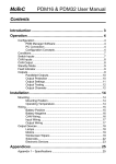
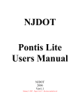
1
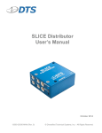
Star 5
Version 1.0.2
Copyright© 2003-2006
MAHTechS®
USER MANUAL
Information can be modified without notice
1
User Manual D 015 013 008 001
MAHTechS srl - Via Per Spilamberto, 4AB
41051 Castelnuovo Rangone (Modena) – ITALY
Telephone +39 059 533 2067 Telefax +39 059 533 2068
E-mail [email protected]
Web www.mahtechs.com
Information can be modified without notice
2
User Manual D 015 013 008 001
Contents
1 Using the Star 5 program...................................................................................................................5
1.1 Description of the graphic interface........................................................................................... 5
1.1.1 Main screen......................................................................................................................... 5
1.1.2 Creating a new configuration.............................................................................................. 6
1.1.3 Loading and saving a document.......................................................................................... 6
1.1.4 Printing a document.............................................................................................................6
1.1.5 Opening/Closing a new tab card..........................................................................................6
1.2 Tab card screens......................................................................................................................... 7
1.2.1 GPS-5 Star tab card............................................................................................................. 7
1.2.2 Data setup tab card.............................................................................................................. 8
1.2.3 Map definition tab card..................................................................................................... 10
1.2.4 Watch channel tabcard...................................................................................................... 23
1.2.5 Performance test tab card.................................................................................................. 25
1.2.6 K-Dash tab card................................................................................................................. 26
1.3 Program preferences................................................................................................................. 31
1.3.1 Tabs position..................................................................................................................... 32
1.3.2 Language........................................................................................................................... 33
1.3.3 Colours.............................................................................................................................. 34
1.3.4 Star tabs............................................................................................................................. 35
1.3.5 Default IP...........................................................................................................................36
1.3.6 Units.................................................................................................................................. 37
1.3.7 Directories......................................................................................................................... 38
1.3.8 Watch channel................................................................................................................... 39
1.3.9 GPS Options (firmware version less than 1.0.5)............................................................... 40
2 Technical information and advanced configurations...................................................................... 41
2.1 Advanced CAN configuration (Data setup tab card)............................................................... 41
2.2 Star 5 Inertial additional CAN Channels..................................................................................42
2.3 Advanced CAN configuration (Performance test tab card)..................................................... 43
2.4 Hexadecimal notation............................................................................................................... 45
2.5 Introduction to CAN channels..................................................................................................46
2.6 Units conversions..................................................................................................................... 47
3 Technical data..................................................................................................................................48
3.1 General..................................................................................................................................... 48
3.2 CAN bus data........................................................................................................................... 48
3.2.1 Format of CAN data.......................................................................................................... 49
3.3 Connector specifications.......................................................................................................... 50
3.4 Specifications........................................................................................................................... 50
3.5 LED specifications................................................................................................................... 51
3.6 Dimensions............................................................................................................................... 51
4 Appendix......................................................................................................................................... 53
4.1 GPS...........................................................................................................................................53
4.1.1 Coordinate systems............................................................................................................53
4.1.2 Distortion........................................................................................................................... 54
4.1.3 Differential operational techniques (DGPS)..................................................................... 54
4.2 Troubleshooting........................................................................................................................55
4.2.1 The device does not switch on...........................................................................................55
4.2.2 It is not possible to connect to the device..........................................................................55
4.2.3 When the device is switched on, all three leds blink.........................................................55
Information can be modified without notice
3
User Manual D 015 013 008 001
4.2.4 The CAN bus does not work............................................................................................. 55
4.2.5 The CAN is operating but the data are not correct............................................................ 55
4.2.6 The latitude and longitude are incorrectly displayed on the SVD.....................................55
4.2.7 The FAST channels return incorrect values in movement................................................ 55
Information can be modified without notice
4
User Manual D 015 013 008 001
1 Using the Star 5 program
The Star 5 program has been designed with the user in mind. The interface is simple and intuitive,
designed to reduce errors to a minimum.
1.1 Description of the graphic interface
This document makes reference to the various parts of the program. Before continuing with the
operational description of the software, we must first take a look at the basic aspects of the
interface.
1.1.1 Main screen
The main screen includes the title bar, menus and toolbar icons, as for most commercial Windows
programs. It also gives a tab card view of the various windows making up the configuration, so as
to make it even easier and friendlier to use.
Toolbar
Navigation
cards bar
(tabs)
Figure 1: Main screen
Information can be modified without notice
5
User Manual D 015 013 008 001
1.1.2 Creating a new configuration
When the program launches, it automatically creates an empty configuration. Any configuration can
be cancelled by simply selecting New from the File menu. The same result can be obtained by
entering CTRL-N or clicking on the new file icon on the toolbar.
1.1.3 Loading and saving a document
As in all programs, entered data can be loaded and saved. To save, use the Save and Save as…
options in the File menu, click on the toolbar icon, or use the corresponding button in the GPS-5
Star card (see paragraph 1.2 for further information on the contents and use of the tab cards). To
load data, use the Load option.
1.1.4 Printing a document
The program allows text printout of all the configurations contained in the tab card screens as well
as graphic map printouts. To print, use the CTRL-P shortcut, the print option in the File menu or the
toolbar button.
1.1.5 Opening/Closing a new tab card
The program allows you to add or close tab cards as required. To add a tab card, go to the Tab menu
and click on Add…, where the three points indicate the card in question.
To close an open tab card, select it and enter CTRL-Q or use the Tab / Close menu option.
NOTE: The tab cards used for sending data to the GPS receiver and for configuring the output
channels cannot be closed inasmuch as they are required for system operation.
Information can be modified without notice
6
User Manual D 015 013 008 001
1.2 Tab card screens
The tab cards contain all the configurations to be sent to the GPS receiver.
Note that any modifications to the program tab cards can be cancelled by clicking on the toolbar
icon Undo, entering CTRL-Z or Edit / Undo.
1.2.1 GPS-5 Star tab card
When the program launches, the Star 5 tab card is active by default (see Figure 2: Star 5 tab card).
This tab card sends the configurations to the receiver, runs file operations and defines the receiver
operating position.
The Setup field has the following options:
• Send data to receiver
• Load a configuration from disk
• Save a configuration to disk
The Device IP field must always contain the real IP assigned to the device otherwise it will not be
possible to establish the configuration connection (see the Ethernet connection rules manual).
The Star 5Orientation field sets the device’s operating position. Use the Next and Previous arrows
to move from one configuration to another. Alternatively use the central bar directly. The selected
position is displayed graphically on the right.
Graphically
displayed
position
Figure 2: Star 5 tab card
Information can be modified without notice
7
User Manual D 015 013 008 001
1.2.2 Data setup tab card
The Data setup tab card configures all the device’s output data (see Figure 3: Data setup tab card) in
other words, everything which will be available (or not) when it is operating.
•
•
•
•
•
•
CAN data out sets the data to be transmitted over the CAN bus network and their
frequencies. The default settings allow the GPS receiver to operate with other MAHTechS
equipment. To further customize the CAN messages, click on the Advanced… button. A
window will open which allows you to set the message ID’s. For further information on
message formats, see paragraph 2.1.
CAN speed sets the speed of the CAN bus. The default value is 500Kb/s.
Data order defines the order in which the bytes of each message are sent. If the received
data are not correct, try modifying this option. The default setting is MSB.
Cutoff freq defines the cutoff frequency (Hz) for accelerations and gyroscopes (only Star 5
Inertial)
Maximum speed sets the speed for which the analogue output voltage is at its maximum.
Precisely calibrating this value increases precision.
PPM defines the number of pulses per meter which the device must output.
Information can be modified without notice
8
User Manual D 015 013 008 001
Figure 3: Data setup tab card
Information can be modified without notice
9
User Manual D 015 013 008 001
1.2.3 Map definition tab card
This page defines the device’s finish line and intermediate points. Other objects can be situated on
the map to complete its contents or already existing maps created with other MAHTechS products
can be imported. The structure of the page is given in Figure 4.
Figure 4: map definition
The objects to be positioned on the map and the main functions are on the left. The rest of the
screen shows the map itself.
The map has been conceived to simplify all operations as far as possible. Almost all operations can
be done with the mouse.
The map has two main modes, which can be described as follows:
•
•
With map points: this case assumes the use of a MAHTechS receiver to acquire a test lap of
the circuit. The data are sent to the receiver over the CAN bus from the GPS device. The
next step is to import the data as map points with the provided button. Now the objects can
be placed on the map (see paragraph 1.2.3.1).
Without map points: in this case, simply start by placing the objects. These objects must
now be assigned latitude and longitude coordinates manually (see paragraph 1.2.3.1.2).
Information can be modified without notice
10
User Manual D 015 013 008 001
1.2.3.1 Editing the map
Throughout the editing phase, all modifications can be cancelled using the Undo toolbar icon,
CTRL-Z or the Edit menu.
The cursor usually has the form of an open hand inside the map space. Other forms of mouse cursor
depend on the operation being run.
1.2.3.1.1 Positioning objects
To position an object on the map, simply click on the corresponding icon on the left of the screen
(see Figure 5: object icons), move the cursor onto the map and select the positioning point. Press the
left mouse button to complete the placement operation. During this operation the mouse cursor will
be represented by two yellow lines. Some objects are composed of more than one point which must
be placed in the same way as the first. If the mouse cursor does not return to its original condition,
this means that the second point is yet to be placed.
NOTE 1: when the mouse cursor stops over an object icon, a window opens to indicate the name of
the object in question.
NOTE 2: when placing an object, the mouse cursor drags the icon of the selected object.
Figure 5: object icons
1.2.3.1.2 Modifying object properties
To modify the properties of an object on the map, double-click on it. A window will open which
allows you to modify its properties. Press OK to confirm or Cancel to abort.
1.2.3.1.3 Cancelling an object
To cancel an object, simply right click on it. The cursor will turn into an X. When the button is
released the object under the X will be deleted.
1.2.3.1.4 Moving an object
To move an object, move the mouse cursor into it and press the left mouse button. The cursor will
turn into a closed hand. Holding down the left mouse button, drag the object into the desired
position. If the object is locked on the map (see paragraph 1.2.3.2) the coordinates of the new
position will display. Release the left mouse button to terminate the drag operation.
Information can be modified without notice
11
User Manual D 015 013 008 001
1.2.3.1.5 Moving the map
When the cursor has the form of an open hand, the map can be moved on the screen by pressing the
left mouse button on an empty space (the cursor turns into a closed hand) and dragging (holding the
button down). Release the mouse button when the operation is completed.
Note 1: if shown, the mini-map object displays the area of the map on the screen in a green
rectangle.
Note 2: the map has outside limits beyond which it cannot be moved.
1.2.3.1.6 Selecting an object underneath another
If several objects are superimposed, it is possible to move from one object to another by holding
down CTRL and clicking on the object. This action cycles through the objects: once it has selected
the last object it starts again with the first one.
Note: when an object is moved the CTRL - Click sequence is cancelled.
Information can be modified without notice
12
User Manual D 015 013 008 001
1.2.3.1.7 Map properties
Double-clicking on an empty area of the map opens the map properties window (see Figure 6: map
properties).
Figure 6: map properties
Map properties:
• Coordinates format: chooses how the latitude and longitude coordinates are displayed. It is
possible to choose between Sexadecimal and decimal. an example of sexadecimal format is
as follows: N 25° 18.6875585 E 51° 31.7414384. The same coordinates would read
+25.311459308, +51.529023973 in decimal format. For further information on the
coordinates system, see paragraph 4.1.1.
• Parallels/meridians: defines how many parallels and meridians are displayed on the map.
Also defines their colour or decides not to displays them.
• Map name: gives the map a name.
• Description: gives the map a description.
• Notify out-of-map objects: gives a notification is any object is placed outside the displayable
map space. This can happen when the coordinates are set manually and an error occurs in
data entry.
1.2.3.2 Map objects
The map objects fall into two main categories.
• objects locked to the map
• objects locked to the screen
The first type of map object has a longitude and latitude defined in the map space (for example an
intermediate point), and are anchored to the map. The second type are information objects, required
for better use of the map (for example, the object which displays the north direction); their position
is independent of the map itself. We list below the available objects together with their properties.
Information can be modified without notice
13
User Manual D 015 013 008 001
1.2.3.2.1 Reference
This is a simple object which, once positioned, indicates the presence of a physical
object, such as a house, camera long the track or other.
The properties of Reference objects are shown in Figure 7.
Figure 7: Reference properties
Reference properties:
• Name: assigns a name to be displayed at the side of the object. If the Show name checkbox
is not selected, the name will not be displayed.
• Name position: indicates the display position for the name relative to the object. Eight
different positions can be specified.
• Position: manually specifies the coordinates of the object. It also has the Hold checkbox
option, which stops the latitude and longitude of the object being changed. A locked object
cannot be moved even with the mouse.
• Colour: specifies the colour of the object. Click on the key at the bottom right to display a
list of predefined colours.
Press OK to confirm or Cancel to abort the modifications.
Information can be modified without notice
14
User Manual D 015 013 008 001
1.2.3.2.2 Time
This is an object composed of two points. The Time object identifies an imaginary
line which, once it is crossed, is associated with a specific operation. Normally this
kind of object is used to indicate the finish line and intermediate points (max. 5) of
the track to the GPS. The properties of Time objects are shown in Figure 8.
Figure 8: time properties
Object properties:
• Name: assigns a name to be displayed at the side of the object. If the Show name checkbox
is not selected, the name will not be displayed.
• Name position: indicates the display position for the name relative to the object. Eight
different positions can be specified.
• Position: manually specifies the coordinates of the object. It also has the Hold checkbox
option, which stops the latitude and longitude of the object being changed. A locked object
cannot
be
moved
even
with
the
mouse.
Since the object is composed of two points, double-click on the other object point to change
its coordinates.
• Colours: specifies the colour of the object, the line connecting the two points and the
permitted error radius (distance). Hold the mouse over the coloured buttons to display their
descriptions.
• Other: specifies the radius of error of a Time object. The radius of error is identified by a
circle drawn at the centre point between the two points composing the object. There is also a
line, perpendicular to the line connecting the two points, which indicates the ideal trajectory
for crossing the Time object. This option also allows the Time object to be specified as the
finishing line. Not that there must always be a finishing line, and that there may be only one
finishing line. Press OK to confirm or Cancel to abort the modifications.
Information can be modified without notice
15
User Manual D 015 013 008 001
1.2.3.2.3 Distance
This object is composed of two points and the distance between them.
Normally this object is used for estimating the distances between objects
or points on the map. The properties of Distance objects are shown in
Figure 9.
Figure 9: distance properties
Object properties:
• Position: manually specifies the coordinates of the object. It also has the Hold checkbox
option, which stops the latitude and longitude of the object being changed. A locked object
cannot
be
moved
even
with
the
mouse.
Since the object is composed of two points, double-click on the other object point to change
its coordinates.
• Colours: specifies the colour of the line connecting the two points and the text giving the
distance between them. Hold the mouse over the coloured buttons to display their
descriptions.
• Units: specifies the units in which the distance is displayed. It is possible to choose between:
meter, kilometer, foot, mile and nautical mile (see paragraph 2.7).
Press OK to confirm or Cancel to abort the modifications.
Information can be modified without notice
16
User Manual D 015 013 008 001
1.2.3.2.4 Label
This is an object composed of two points used to add information to a map. The
properties of Label objects are shown in Figure 10.
Figure 10: label properties
Object properties:
• Name: modifies the name to be displayed. If the Hold checkbox is selected, the object
cannot be moved.
• Colour: changes the colour of the label’s background.
Press OK to confirm or Cancel to abort the modifications.
1.2.3.2.5 North
This object displays the geographical north. It is a four pint compass: the red point is the
north. The properties of the North object are shown in Figure 11.
Figure 11: north properties
Object properties:
• Position: locks the object in position on the screen (Hold checkbox). A locked object cannot
be
moved
even
with
the
mouse.
Also specifies whether the object is to be transparent or not (Transparent checkbox).
Press OK to confirm or Cancel to abort the modifications.
Information can be modified without notice
17
User Manual D 015 013 008 001
1.2.3.2.6 Scale
This object displays the scale as in traditional maps. The properties of the Scale
object are shown in Figure 12.
Figure 12: scale properties
Object properties:
• Units: specifies the units in which the scale is displayed. It is possible to choose between:
meter, kilometer, foot, mile and nautical mile (see paragraph 2.7).
• Other: locks the object in position on the screen (Hold checkbox). A locked object cannot be
moved even with the mouse. Also specifies whether the object is to be transparent or not
(Transparent checkbox).
Press OK to confirm or Cancel to abort the modifications.
1.2.3.2.7 Mini map
This object constantly displays the current display position of the map, which is
valuable when working with very high zoom factors. It also allows the user to move
quickly from one point of the map to another by simply clicking. The properties of
the Mini map object are shown in Figure 13.
Figure 13: mini map properties
The mini-map object displays the area of the map on the screen in a green rectangle.
Object properties:
Information can be modified without notice
18
User Manual D 015 013 008 001
•
•
•
Show: selects the additional information to display on the mini map (references,
intermediate points, labels, etc.).
Position: If the Hold checkbox is selected, the object cannot be moved.
Left click: associates an action with a single left click on the object. The default action is Go
to, which centers the map on the point clicked on with the mouse. Move, on the other hand,
allows the map to be moved with the mouse.
Press OK to confirm or Cancel to abort the modifications.
1.2.3.3 Map function
The map functions allow the user to define values like zoom and rotation, to import and export
maps and reposition objects when working with maps without map points (see paragraph 1.2.3).
The map functions are located at the bottom left and shown in Figure 14.
Figure 14: functions
1.2.3.3.1 Importing maps
The user can import maps in a variety of formats used by MAHTechS products, as described below:
• Star 5 map file (*.gmp): the file contains a complete map (map points and objects). This is
the native map file format for the Star 5 device.
• Star 5 configuration file (*.gfg): Star 5 configuration file; only the map contained in the file
is imported. This is the native file format for saving a complete setup, including map.
• Analyzer map points (*.pmf): file post-processed by the Analysis program. Only the map
points can be imported.
• Analyzer/SVD-Editor map objects (*.map): imports the map objects (not map points)
generated by the Analysis or SVD Editor software.
• Analyzer/Star 5 exported map points (*.txt): map points exported by the Star 5 or Analysis
program.
There are special precautions to be taken when importing certain formats, as described below.
Information can be modified without notice
19
User Manual D 015 013 008 001
Native formats (gmp and gfg)
Importation of a native file enables full use to be made of the advanced characteristics of the map.
In particular, the user can choose to import only the map points or only the objects, or when
choosing one of these options, whether to maintain or discard the objects or ma points shown in the
current display (see Figure 15). This functionality can be useful, for example, when more than one
lap of the track is available: they can be loaded one at a time (deleting the previous one) without the
need to reposition the objects.
NOTE: loading objects or map points which are not logically compatible will give rise to error
messages or failure to display the objects.
Figure 15: import native map
Post-processed format (pmf)
A post-processed file contains information on the whole installed acquisition system; importing the
map points from a post-processed file therefore requires some additional information. The program
displays a window (see Figure 16) which displays information on the selected file. Select the laps to
import from the list to the left, the latitude and longitude channels from the channel list. It is also
possible to specify whether or not the data are calibrated.
Figure 16: importing from a post-processed file
Information can be modified without notice
20
User Manual D 015 013 008 001
1.2.3.3.2 Exporting maps
The program allows the user to export the map alone in a file separate from the configuration. The
follow export formats are available:
• Star 5 map file (*.gmp): native format of the Star 5 program. Use this option if you wish to
save the map alone for future use.
• Star 5 text file (not importable; *.txt): exports a map in a legible text format. This file can be
used for importing the map points alone (the objects contained in them cannot be reimported).
1.2.3.3.3 Repositioning objects
When working without map points (for example, if you do not have an acquisition unit), you can
enter the finishing line and intermediate point data manually. To do this you must know the
coordinates (longitude and latitude) of the objects in question. At this point, position the objects on
the map, edit their properties with the correct longitude and latitude values and click on Replace
objects in the function bar (bottom icon in Figure 14). The objects will be placed in the correct
position on the map: this allows you to check their positioning visually.
We show below an example of non-positioned objects (Figure 17), which are then positioned with
the above function (Figure 18).
Figure 17: non-positioned objects
Information can be modified without notice
21
User Manual D 015 013 008 001
Figure 18: repositioned objects
Information can be modified without notice
22
User Manual D 015 013 008 001
1.2.4 Watch channel tabcard
This screen gives a real time readout of the values supplied by the device. When the tabcard is
activated, the program attempts to establish an Ethernet connection with the device using the IP
address in the Star 5 page (see paragraph 1.2.1). If the connection succeeds, the real time values will
start scrolling down the screen (see Figure 19: watch channel).
Figure 19: watch channel
The watch channels can always be started and stopped using the Star 5 menu options Start watch
channel and Stop watch channel.
To disable real time acquisition of data in one or more channels, simply click off the checkboxes to
their left. The units of the displayed data can also be changed: double-clicking on a value opens its
properties window (see Figure 20: ). Select the desired units and click on OK. The watch channel
values will be automatically converted to the selected units.
Information can be modified without notice
23
User Manual D 015 013 008 001
Figure 20: watch channel properties
Information can be modified without notice
24
User Manual D 015 013 008 001
1.2.5 Performance test tab card
This screen (see Figure 21: Performance test) sets the GPS to run performance tests on one or more
vehicles with units of meters/feet for distances and kmh/mph for speeds.
Figure 21: Performance test
Up to ten tests can be programmed each of which can be chosen from among the four available
types, as described below:
• Acceleration (speed): calculates the time and distance required to accelerate from 0 to the
speed set in the program.
• Acceleration (distance): calculates the time and final speed for travelling a certain distance
set in the program, from a standing start.
• Acceleration (torqued): calculates the time and final speed for a pickup test in travelling a
certain distance set in the program, from a given initial speed.
• Braking: calculates the distance required to decelerate from the speed set in the program to
0.
To move from one test to another, press the button supplied with the GPS device.
Information can be modified without notice
25
User Manual D 015 013 008 001
1.2.6 K-Dash tab card
In this page (Figure 22: ) the CAN channels for the device can be associated with areas of the
MAHTechS K-Dash display. Move the mouse over the indicators to highlight them; left click to
open the configuration window. It is also possible to import/export a configuration from/to a KFG
file (configuration file for the program provided with the K-Dash device) and modify the monitor
contrast, which is handy when using an LCD display.
Figure 22: K-Dash
Information can be modified without notice
26
User Manual D 015 013 008 001
1.2.6.1 Speed area
The speed area is located at the top left and is composed of three numbers plus two labels: Kmh and
Mph. Left click on the field to display the window shown in Figure 23 as described below.
•
•
The Channel field associates the speed area with a selected channel for transmission over
the CAN. Click on the down arrow to display the complete list of available channels.
Use the label group to decide whether and which label will be displayed from among those
available. Select from Off (no label), Kmh and Mph.
Confirm with OK and abort with Cancel. When the window opens, the previously entered and
confirmed (OK) data are displayed. If the new data are confirmed, the corresponding area of the
display page will activate and display the new settings graphically.
Figure 23: speed area
1.2.6.2 Gear area
The gear area is located at the top centre and is composed of an alphanumeric field plus one label
(Gear). Left click on the field to display the window shown in Figure 24 as described below.
•
•
The Channel field associates the gear area with a channel. Click on the down arrow to
display the complete list of available channels.
Use the Gear Label checkbox to specify whether or not the Gear label is to be displayed.
Confirm with OK and abort with Cancel. When the window opens, the previously entered and
confirmed (OK) data are displayed. If the new data are confirmed, the corresponding area of the
display page will activate and display the new settings graphically.
Figure 24: gear area
Information can be modified without notice
27
User Manual D 015 013 008 001
1.2.6.3 Rpm area
The rpm area is located at the top right and is composed of five number plus the Rpm label. Left
click on the field to display the window shown in Figure 25 as described below.
•
•
The Channel field associates the Rpm area with a channel defined in the grid in the CAN
Setup page. Click on the down arrow to display the complete list of available channels.
Use the RPM Label checkbox to specify whether or not the Rpm label is to be displayed.
Confirm with OK and abort with Cancel. When the window opens, the previously entered and
confirmed (OK) data are displayed. If the new data are confirmed, the corresponding area of the
display page will activate and display the new settings graphically.
Figure 25: rpm area
1.2.6.4 Lap area
The Lap area is located at the bottom centre and is composed of two numbers plus the Lap label.
Left click on the field to display the window shown in Figure 26 as described below.
•
•
The Channel field associates the Lap area with a channel. Click on the down arrow to
display the complete list of available channels.
Use the Lap Label checkbox to specify whether or not the Lap label is to be displayed.
Confirm with OK and abort with Cancel. When the window opens, the previously entered and
confirmed (OK) data are displayed. If the new data are confirmed, the corresponding area of the
display page will activate and display the new settings graphically.
Figure 26: lap area
Information can be modified without notice
28
User Manual D 015 013 008 001
1.2.6.5 Characters area
The two characters areas are located at the bottom left and bottom right. Each is composed of five
alphanumeric fields and two rows of labels:
•
•
Row 1 (top): Boost, Oil, Water.
Row 2 (bottom): Psi (pressure in weight per square inch), Bar (pressure in bar), °C (degrees
centigrade), °F (degrees Fahrenheit), Lap time.
Left click on the field to display the window shown in Figure 27 as described below.
•
•
•
The Channel field associates the characters area with a channel. Click on the down arrow to
display the complete list of available channels. If the field is not associated with any channel
(---), the characters area can be used to display the text specified in the Text field.
Use the Label 1 group to decide which label will be displayed from row 1; select Off to not
display any of them.
Use the Label 2 group to decide which label will be displayed from row 2; select Off to not
display any of them.
Confirm with OK and abort with Cancel. When the window opens, the previously entered and
confirmed (OK) data are displayed. If the new data are confirmed, the corresponding area of the
display page will activate and display the new settings graphically.
Figure 27: characters area
Information can be modified without notice
29
User Manual D 015 013 008 001
1.2.6.6 Combining K-Dash and Performance Test (example)
The option of defining and saving a configuration for a K-display is particularly useful when using
the device for performance tests (see paragraph 1.2.5).If you include a Performance Test tab card in
the Star 5 device configuration, five CAN channels are automatically defined which can then be
associated with areas of the K-Dash. The follow channels are available:
• S5_PF_INPUT_PAR1: first test parameter (if definable, otherwise 0). This channel can be
associated with the Speed area of the display.
• S5_PF_INPUT_PAR2: second test parameter (if definable, otherwise 0). This channel can
be associated with the RPM area of the display.
• S5_PF_DIST_SPEED_RESULT: channel which indicates the distance or speed, according
to the test run. This channel can be associated with one of the two Characters areas of the
display.
• S5_PF_TIME_RESULT: channel which indicates the time of execution of the test run. This
channel can be associated with one of the two Characters areas of the display (make sure to
activate the Time label as well).
• S5_PF_IDTEST: channel which indicates the type of the test run with the following values.
1: acceleration (speed), 2: acceleration (distance), 3: acceleration (torqued), 4: brake. This
channel can be associated with the Gear area of the display.
At this point, save the configuration to the disk (for example, with the name performance.gfg) and
send the data to the GPS device. The K-Display configuration is done with the program defined by
it:
• Open the K-Dash configuration program
• From the File menu, click on Import and select the previously saved GPS configuration file
(performance.gfg).
• At this point the first page defined in the GPS program will appear in the K-Dash program,
complete with the definitions of the CAN channels. Send this configuration to the K-Dash to
terminate the configuration process.
Now the Star 5 is set to run the performance tests and the K-Dash will display the results in real
time. To move from one test to another, press the button supplied with the Star 5 device.
Information can be modified without notice
30
User Manual D 015 013 008 001
1.3 Program preferences
It is possible to customize the operation of the program with the Edit menu Preferences option. The
window shown in Figure 28 will display.
Figure 28: program preferences
A tree with the various options displays to the left. Use the mouse to select the desired option. The
right side of the window will change depending on the selection.
At the end of the operation, press OK to confirm or Cancel to abort the modifications.
Information can be modified without notice
31
User Manual D 015 013 008 001
1.3.1 Tabs position
This positions the tabs bar. When the program is launched, the tabs bar is at the top left; it can be
placed at any point of the window according to preference. Select the desired position (see Figure
29: ) and press OK to confirm or change the object to modify other settings.
Figure 29: tabcard positions
Information can be modified without notice
32
User Manual D 015 013 008 001
1.3.2 Language
The Star 5 device supports a variety of languages. The installed languages are displayed in the
window (see Figure 30). Select the desired language and press OK to confirm or change the object
to modify other settings. The program must be relaunched to activate the changes.
Figure 30: language
Information can be modified without notice
33
User Manual D 015 013 008 001
1.3.3 Colours
This option enables you to change the program’s colours. The default colours can always be reset
by clicking on Reset to default. Select the desired colours and press OK to confirm or change the
object to modify other settings.
Figure 31: colours
Information can be modified without notice
34
User Manual D 015 013 008 001
1.3.4 Star tabs
This window (shown in Figure 32: ) enables you to decide which tab cards will appear the next time
the program is run. Select the desired tab cards and press OK to confirm or change the object to
modify other settings. Tab cards can always be added or removed with the Tab card menu.
NOTE: The Star 5 and Data setup are always displayed.
Figure 32: start tabs
Information can be modified without notice
35
User Manual D 015 013 008 001
1.3.5 Default IP
When the program is launched, it displays an IP address in the Star 5 page. The IP displayed can be
changed at any time with this window (see Figure 33). Two buttons are provided to facilitate the
operation:
• Use factory IP sets the IP stored in the program, displayed the first time it is launched.
• Use current IP sets the default to the IP currently displayed in the Star 5 page.
The initial IP for the current session can also be set by clicking on the Set now checkbox.
The value displayed when this page is opened is the current default setting. Modify the value and
press OK to confirm or change the object to modify other settings.
Figure 33: default IP
Information can be modified without notice
36
User Manual D 015 013 008 001
1.3.6 Units
Both the map and the watch channels display values with various units of measurement. The
program’s default values may not be suitable for the current application or national standards. Use
this window (see Figure 34) to set the default units for the program so as not to have to change them
every time. Select the desired units and press OK to confirm or change the object to modify other
settings.
Figure 34: units
Information can be modified without notice
37
User Manual D 015 013 008 001
1.3.7 Directories
The Star 5 program uses a default folder for saving and loading files, which may vary from user to
user or always be set to the same location. This window (Figure 35) enables you to:
• Use the default MAHTechS directory: this is a folder common to all users created during
installation of the program (default value)
• Use last directory: the program stores the most recently used folder and prompts with it at
the next save or load operation (varies from user to user).
• Use custom directory: set a folder which is common to all users of the computer.
Select your desired method and press OK to confirm or change the object to modify other settings.
Figure 35: folders
Information can be modified without notice
38
User Manual D 015 013 008 001
1.3.8 Watch channel
Defines the actions taken and the times to be applied when entering the watch channel tab card. The
window options are (see Figure 36: watch channel):
• Channels auto-selection sets the program to automatically select all active channels. The
selection is made on the basis of the channels selected for sending messages over the CAN.
• Clean on start deletes the values of the inactive channels when the watch channel is
activated.
• Start automatically attempts to start the watch channel every time the tab card is opened.
• Refresh rate sets the display refresh rate in hundredths of a second.
Select the desired settings and press OK to confirm or change the object to modify other settings.
Figure 36: watch channel
Information can be modified without notice
39
User Manual D 015 013 008 001
1.3.9 GPS Options (firmware version less than 1.0.5)
Sets the options to be used by the GPS receiver for data calculation. The window options are shown
in Figure 37 as described below:
• Use DGPS (SBAS): sets differential operation for automatic error correction. The GOS
receiver can hook to up to two additional SBAS satellites (WAAS, EGNOS and MSAS)
which provide error correction parameters.
• Kalman filter: this option is only available in DGPS mode. The Kalman filter harmonises
the speed and position data in real time and is especially valuable in areas where the GPS
signal fluctuates, such as in tree-lined avenues or built-up areas.
Select the desired options and press OK to confirm or change the object to modify other settings.
NOTE: Once the windows options have been modified, you must send the new configuration to the
GPS to activate them.
IMPORTANT: Deselecting these fields may decrease the accuracy of the GPS device. Using these
functions normally increases the precision of the device, but the SBAS system is still experimental
and its operation is not guaranteed.
Figure 37: options
Information can be modified without notice
40
User Manual D 015 013 008 001
2 Technical information and advanced configurations
2.1 Advanced CAN configuration (Data setup tab card)
The default settings for the configuration software ensure simple and direct operation of
MAHTechS products. However, it is possible to customize the CAN message ID’s to enable the
device to operate under any conditions (see Figure 38: ). The default ID’s can always be reset by
clicking on the Default.
Figure 38: advanced CAN configuration (1)
If the latitude and longitude values are not displayed correctly by the MAHTechS display, try
enabling the option Compatibility mode.
Information can be modified without notice
41
User Manual D 015 013 008 001
We give below the internal structure of the CAN messages sent by the device. For further
information, refer to paragraphs 2.5 and 2.6. For CAN calibration refer to paragraph 3.2.1.
BIT
0
8
16
24
32
40
48
56
ID=0x230
BIT
0
8
16
24
32
40
48
56
ID=0x231
BIT
0
8
16
24
32
ID=0x233
40
48
56
BIT
0
8
16
24
32
40
48
56
Fmax=100Hz
FAST LATITUDE (0-7)
FAST LATITUDE (8-15)
FAST LATITUDE (16-23)
FAST LATITUDE (24-31)
FAST LONGITUDE (0-7)
FAST LONGITUDE (8-15)
FAST LONGITUDE (16-23)
FAST LONGITUDE (24-31)
BIT
0
8
16
24
32
40
48
56
ID=0x237
Fmax=20Hz
GPS LATITUDE (0-7)
GPS LATITUDE (8-15)
GPS LATITUDE (16-23)
GPS LATITUDE (24-31)
GPS LONGITUDE (0-7)
GPS LONGITUDE (8-15)
GPS LONGITUDE (16-23)
GPS LONGITUDE (24-31)
Fmax=100Hz
FAST ALTITUDE (0-7)
FAST ALTITUDE (8-15)
FAST SPEED (0-7)
FAST SPEED (8-15)
DISTANCE (0-7)
DISTANCE (8-15)
DISTANCE (16-23)
DISTANCE (24-31)
BIT
0
8
16
24
32
40
48
56
ID=0x232
Fmax=20Hz
GPS ALTITUDE (0-7)
GPS ALTITUDE (8-15)
GPS SPEED ORIZ (0-7)
GPS SPEED ORIZ (8-15)
GPS SPEED VERT (0-7)
GPS SPEED VERT (8-15)
Fmax=100Hz
COG (0-7)
COG (8-15)
COG MAGNETIC (0-7)
COG MAGNETIC (8-15)
UTC (0-7)
BIT
0
8
16
24
32
ID=0x234
UTC (8-15)
UTC (16-23)
COUNTER
N. SAT
ID=0x235
40
48
56
Fmax=100Hz
ACC X (0-7)
ACC X (8-15)
ACC Y (0-7)
ACC Y (8-15)
ACC Z (0-7)
ACC Z (8-15)
BIT
0
8
16
24
32
40
48
56
Fmax=100Hz
LAP PULSE (0-7)
SPLIT PULSE (0-7)
comp.
mode
LAP TIME (0-7)
LAP TIME (8-15)
SPLIT TIME (0LAP TIME (16-19)
3)
SPLIT TIME (4-11)
SPLIT TIME (12-19)
ID=0x234
Fmax=100Hz
LAP TIME (0-7)
LAP TIME (8-15)
LAP TIME (16-23)
LAP PULSE (0-7)
SPLIT TIME (0-7)
SPLIT TIME (8-15)
SPLIT TIME (16-23)
SPLIT PULSE (0-7)
The LAP PULSE and SPLIT PULSE messages have a duration of 60 milliseconds and cannot be
present if the LAP TIME and SPLIT TIME messages are also present.
Information can be modified without notice
42
User Manual D 015 013 008 001
2.2 Star 5 Inertial additional CAN Channels
We give below the internal structure of the CAN messages sent by the inertial device.
BIT
0
8
16
24
32
40
48
56
ID=0x23B
Fmax=100Hz
SPEED X (0-7)
SPEED X (8-15)
SPEED X (16-19)
SPEED Y (0-3)
SPEED Y (4-11)
SPEED Y (12-19)
SPEED Z (0-7)
SPEED Z (8-15)
SPEED Z (16-19)
BIT
0
8
16
24
32
40
48
56
ID=
Fmax=100Hz
BIT
0
8
16
24
32
40
48
56
ID=0x23C
Fmax=20Hz
PITCH (0-7)
PITCH (8-15)
ROLL (0-7)
ROLL (8-15)
YAW (0-7)
YAW (8-15)
BIT
0
8
16
24
32
40
48
56
ID=0x23A
Fmax=100Hz
GYRO X (0-7)
GYRO X (8-15)
GYRO Y (0-7)
GYRO Y (8-15)
GYRO Z (0-7)
GYRO Z (8-15)
2.3 Star 5 Tracker additional CAN Channels
We give below the internal structure of the CAN messages sent by the tracker device.
BIT
0
8
16
24
32
40
48
56
ID=0x23B
Fmax=100Hz
AVERAGE INCREMENTAL SPEED (0-7)
AVERAGE INCREMENTAL SPEED (8-15)
AVERAGE LAP SPEED (0-7)
AVERAGE LAP SPEED (8-15)
BIT
0
8
16
24
32
40
48
56
ID=
Fmax=
BIT
0
8
16
24
32
40
48
56
ID=
BIT
0
8
16
24
32
40
48
56
ID=
Fmax=
Fmax=
Information can be modified without notice
43
User Manual D 015 013 008 001
2.4 Advanced CAN configuration (Performance test tab card)
The default settings for the configuration software ensure simple and direct operation of
MAHTechS products. However, it is possible to customize the CAN message ID’s to enable the
device to operate under any conditions (see Figure 39: ). The default ID’s can always be reset by
clicking on Default.
Figure 39: advanced CAN configuration
We give below the internal structure of the CAN messages sent by the device. For further
information, refer to paragraphs 2.3 and 2.4. For CAN calibration refer to paragraph 3.2.1.
BIT
0
8
16
24
32
40
48
56
ID=0x238
Fmax=100Hz
Result time (0-7)
Result time (8-15)
Result time (16-23)
Distance or Speed (0-7)
Distance or Speed (8-15)
Distance or Speed (16-23)
Test state (0-7)
Test info (0-7)
BIT
0
8
16
24
32
40
48
56
ID=0x239
Fmax=100Hz
ID prova (0-7)
Aux chan (0-7)
Aux chan (8-15)
Aux chan (16-23)
Param 1 (0-7)
Param 1 (8-15)
Param 2 (0-7)
Param 2 (8-15)
Message 0x238 sends the test data. The test result is returned as a distance or speed (not both)
and/or a time.
In more detail:
• Acceleration (speed) -> returns the time and distance of the test run
• Acceleration (space) -> returns the time and final speed of the test run
• Brake -> returns the time and braking distance
• Acceleration (torqued) -> returns the time and final speed of the test run
Message 0x239 indicates the test and the input values (specified in the program) for the test run:
Information can be modified without notice
44
User Manual D 015 013 008 001
•
•
•
•
Test ID is the number associated with the type of test run; 1: acceleration (speed), 2:
acceleration (distance), 3: pickup, 4: brake.
Param 1 is a test parameter
Param 2 is a second test parameter (if applicable)
Aux chan is an analysis channel.
Information can be modified without notice
45
User Manual D 015 013 008 001
2.5 Hexadecimal notation
The ID of the messages used in the program is given in the 0xddd notation which indicates that the
value is in hexadecimal format, that is, in base 16 rather than base 10.
The hexadecimal system uses 16 digits:
0; 1; …; 9; A; B; C; D; E; F;
where A=10, B=11, … F=15
The conversion rules from hexadecimal to decimal and viceversa are as follows:
Hexadecimal – decimal conversion
Multiply each digit of the number by 16 to the power of the position of the digit within the number.
The position starts with 0 and runs from right to left.
E.G.: 3EA216 = 3x163 + 14x162 + 10x161 + 2x160 = 12288 + 3584 + 160 + 2 = 1603410
Decimal – hexadecimal conversion
Divide the decimal number by 16; the remainder is the first digit of the hexadecimal number.
Repeat the operation on the quotient of the previous division until the quotient itself is zero. At each
division, the remainder is the next digit of the hexadecimal number.
Quotient
Remainder
1002
62
3
0
2
10
14
3
16034 : 16 =
1002 : 16 =
62 : 16 =
3 : 16 =
Hexadecimal
equivalent of
the
remainder
2
A
E
3
Hence we have again:1603410 = 3EA216
Information can be modified without notice
46
User Manual D 015 013 008 001
2.6 Introduction to CAN channels
The data are sent over the CAN bus from the device. This is a serial connection based on data
packets or messages travelling over the bus. Each message has 11 bits reserved to an ID value
(arbitration ID) which must be unique, and 64 bits for the data being transmitted.
Within this space of 64 bits, one or more channels can be defined. Channels are simply subgroups
of the available 64 bits which are logically associated with each other, and with which a set of
parameters can be defined which are of value to the devices for interpreting the data correctly.
An example definition of channels on a message would be as follows:
message 0x201
message 0x23A
0
15
16
RPM Left
31
RPM Right
0
47
Oil Pressure Left
31
Latitude
32
48
63
Oil Pressure Right
32
63
Longitude
The ID of the message is given in the 0xddd notation which indicates that the value is in
hexadecimal format, that is, in base 16 rather than base 10.
Information can be modified without notice
47
User Manual D 015 013 008 001
2.7 Units conversions
The Star 5 returns values in the SI system of units. The programming software also gives values in
other systems of units.
For the sake of completeness, we give here some useful conversion values:
Unit (SI)
1000 meters
1 km
3280.83 feet
0.621 miles
1 m/s
1 kmh
3.60 kmh
0.2778 m/s
3.28083 feet/s
0.9113 feet/s
2.237 mph
0.6214 mph
Information can be modified without notice
48
0.540 nautical
miles
1.944 knots
0.540 knots
User Manual D 015 013 008 001
3 Technical data
3.1 General
•
•
•
•
•
•
•
•
•
•
•
•
•
•
•
•
•
•
•
•
•
•
Advanced GPS receiver with up to 14 satellite reception
Remote start/stop button for precise distance measurements
Autonomous horizontal position measurement with precision 1.50m CEP (0.4m DGPS)
Relative position measurement with precision 0.4m over 1000m
Maximum speed: 500Km/h
Speed precision: 0.1m/sec
Internal accelerometers on the X, Y and Z axes
Optional external gyroscopes
Configuration with direct GPS antenna (motorcycling applications only) or remote antenna
Programmable frequency proportional to the frequency (tone wheel simulation)
0-5 Volt analogue output proportional to speed (16 bit precision)
Lap Trigger digital output programmable with geographical coordinates (latitude and
longitude)
Split Trigger digital output programmable with geographical coordinates (latitude and
longitude)
Stand alone or differential operation
Power: 8 – 32 Volt DC
N°1 CAN interface (standard 1Mbit/s part A&B)
N°1 Ethernet port 10/100Mbit/sec
Programming software compatible with M5X Data Logger MAHT5-PRO Analysis software
under Microsoft® Windows® NT/2000/XP
Device fully programmable via ethernet connection
Autosport/MIL 38999 37pin connector + SMA connector for the antenna
Ultralight, compact aluminium/carbon fibre housing, protection rating IP67, anodized
(140.15x67.4x43mm)
Operating temperature -20 ° to 70 °C
3.2 CAN bus data
The programming software can be used to define the parameters to send to the devices connected to
the CAN bus. The data are listed below:
•
•
•
•
•
•
•
•
•
•
Fast latitude
Longitude
Fast altitude
Fast speed
GPS latitude
GPS longitude
GPS altitude
GPS speed
True COG
Magnetic COG
●
●
●
●
●
●
●
●
●
●
Information can be modified without notice
UTC
Satellites
Lap time
Intermediate times
X acceleration
Y acceleration
Z acceleration
Gyroscope
Distance
Finish line/intermediate point pulse
49
User Manual D 015 013 008 001
Additional channels of Star 5 Inertial:
• Gyro X
●
Speed X
• Gyro Y
●
Speed Y
• Gyro Z
●
Speed Z
• Pitch, Roll, Yaw
If performance test is active, additional channels are listed below:
• ID Test
●
Test state
• Parameter 1
●
Parameter 2
• Result 1
●
Result 2 (time)
• Aux chan
3.2.1 Format of CAN data
Here are listed the calibrations for the CAN values.
Latitude / Longitude
Altitude
UTC
Time
COG
Speed Oriz
Distance
Acceleration X, Y, Z
Gyro X, Y, Z
Speed X, Y, Z and Speed GPS
Vert
Pitch, Roll, Yaw
Information can be modified without notice
Divide the value for 10000000. The result is latitude/longitude
in decimal notation. Signed channel.
Value in meters. Signed channel.
Hundredth of second. Unsigned channel.
Hundredth of second. Unsigned channel.
Divide the value for 100. Result is degrees and decimal
degrees. Unsigned channel.
Divide the value for 100. Result is km/h. Unsigned channel.
Value in centimeters. Unsigned channel.
Thousandth of G. Signed channel.
Hundredth of °/sec. Signed channel.
Speed. Value per 100. Signed channel.
Divide the value for 100. Result is degrees and decimal
degrees. Signed channel.
50
User Manual D 015 013 008 001
3.3 Connector specifications
AS214-35PN connector
AS614-35SN coupling connector
PIN
DESCRIPTION
1
2
9
10
12
13
14
15
16
17
18
19
20
21
22
23
24
25
26
27
28
29
+ Battery input
– Battery output
Battery output 1 with 500mA fuse
GND
Battery output 2 with 500mA fuse
GND
Button input
Button reference
Lap Time output pulse (LTP)
LTP GND
Split Time output pulse (STP)
STP GND
Pulse per metre output (SPM)
SPM GND
0 – 5 Volt DC analogue speed output (ASP)
ASP GND
Ethernet TX+
Ethernet TXEthernet RX+
Ethernet RXCAN H
CAN L
Unspecified pins are reserved. Specifications subject to change without notice.
3.4 Specifications
DESCRIPTION
Power voltage
Current absorption Star 5 Tracker
Current absorption Star 5 Inertial
Operating temperature
Storage temperature
Weight Star 5 Tracker
Weight Star 5 Inertial
Environmental specifications
Information can be modified without notice
VALUE
8 / 32 Volt DC
300mA@12Volt DC
350mA@12Volt DC
- 20 / +70°C (-68 / +158°F)
- 40 / +85°C (-104 / +185°F)
350 gr (12.3 ounces)
450 gr (15.8 ounces)
IP67
51
User Manual D 015 013 008 001
3.5 LED specifications
The device has three LEDS on its front panel: one green, one yellow and one red. These leds are
used to indicate the current operation:
• Red led: indicates that the device’s Ethernet port is busy
• Yellow led: indicates that the device is transmitting over the CAN
• Green led: counts the number of satellites currently in use. The number of satellites is given
visually as the number of flashes. Count the number of times the green led turns on to
determine the number of satellites. This function is always active, and the start of the
sequence is preceded by a longer pause in which the led is off.
3.6 Dimensions
Figure 40: dimensions in mm (and inches)
Information can be modified without notice
52
User Manual D 015 013 008 001
Information can be modified without notice
53
User Manual D 015 013 008 001
4 Appendix
4.1 GPS
GPS is the acronym for Global Positioning System. Initially developed by the US armed forces, it
soon became one of the basic tools of global information systems, including commercial
applications. Since it is a strategic technology, the US government retains the right to prevent
hostile uses of the system and degrade its performance in military areas or areas in which
military operations are in progress. Such intervention does not affect the performance of the
system in areas not subject to such concerns.
The basic GPS system is composed of a network of orbiting satellites which send signals to the
ground during their orbits. These signals are used by the GPS receiver to determine the information
required for navigation on any point of the Earth’s surface, day or night.
4.1.1 Coordinate systems
The GPS system enables the user to know his position at any time, in latitude and longitude (as
used in maps).
The equator is the zero for latitude and positive values are to the north and south of it (to a
maximum of 90° at the poles); they therefore describe circles of increasingly smaller radius parallel
with the equator. This is why all such lines are called parallels.
The longitude lines, also known as meridians, all intersect the north and south poles. The zero line
for longitude value passes through Greenwich in London, England. Meridians increase in value to
the east and west to a maximum of 180°.
The couple latitude/longitude uniquely describes any point on the earth’s surface.
4.1.1.1 Base 60 notation
A widely used coordinate system uses base 60 notation (also known as Degree Decimal Minutes ->
DDM) in which each degree is divided into 60 minutes and each minute is expressed with decimal
values. An example of coordinates expressed in DDM would be N 25° 18.68 E 51° 31.74, as
described below:
• N 25° 18.68 indicates the parallel. N indicates that the parallel lies to the north of the
equator; 25 gives the degrees of latitude and 18.68 the minutes (with two significant decimal
digits)
• E 51° 31.74 indicates the meridian. E indicates that the meridian lies to the east of the
Greenwich line; 51 gives the degrees of longitude and 31.74 the minutes (with two
significant decimal digits)
4.1.1.2 Decimal notation
Another system of coordinates is that expressed in decimal notation. An example of this notation
would be +25.31146, +51.52902 as described below:
• +25.31146 (the first value) indicates the parallel; + indicates that it lies to the north (while –
indicates the south) and 25.31146 are the degrees of latitude
• +51.52902 (the second value) indicates the meridian; + indicates that it lies to the east
(while – indicates the west) and 51.52902 are the degrees of longitude.
Information can be modified without notice
54
User Manual D 015 013 008 001
4.1.2 Distortion
Maps, with the exception of specialized maps of the poles, are flat while the Earth is spherical. The
“flattening” used to draw maps creates distortions. These distortions are effectively imperceptible
on large scale maps (i.e. maps which describe a small area), but they complicate the use of the
coordinate system.
Classical maps use the Mercator projection to draw the map and make it more easily
comprehensible (see Figure 41).
Figure 41: cylindrical Mercator projection
4.1.3 Differential operational techniques (DGPS)
The idea underlying the use of differential operation consists in the correction of a measurement via
the known error in a known position, thus increasing the precision of the device. To this end, base
stations are provided (usually ground based) which constantly transmit the correction signal.
Clearly, such stations may not be too distant from the position of the receiver and the GPS device
must be equipped to use them.
If the user is not within the useful range of a ground station, it is possible to use an independent
fixed ground station which is compatible with the product. This latter solution is clearly more
expensive, but it guarantees high precision of the data and yields the highest performance of the
device.
Information can be modified without notice
55
User Manual D 015 013 008 001
4.2 Troubleshooting
4.2.1 The device does not switch on
Check that the power supply is within the manufacturer’s specifications and that it is correctly
connected (polarity). For further information, refer to paragraph 3.3.
4.2.2 It is not possible to connect to the device
Check that the device and your PC are connected to a HUB or switch. To connect the device
directly to your PC, use a crossover Ethernet cable. Also refer to the Ethernet connection manual
provided with the product.
4.2.3 When the device is switched on, all three leds blink
The internal backup battery is discharged. Return the product to the manufacturer for replacement
of the battery.
4.2.4 The CAN bus does not work
Check that the device is set to the correct Baud rate (see paragraph 1.2.2) and check the polarity of
the CAN connection.
4.2.5 The CAN is operating but the data are not correct
Try inverting the order of the data on the CAN (MSB or LSB). For further information, refer to
paragraph 1.2.2.
4.2.6 The latitude and longitude are incorrectly displayed on the SVD
Enable Compatibility mode in the CAN advanced properties window. For further information, refer
to paragraph 2.1.
4.2.7 The FAST channels return incorrect values in movement
Check that the device has been mounted in the position specified in the configuration. For further
information, refer to paragraph 1.2.1.
Information can be modified without notice
56
User Manual D 015 013 008 001