1
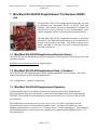
Moog Components Group
Mini-Mux 2 RS-422/485 Daughterboard, Rev B
(200860-xxx)
February 24, 2009
Mini-Mux 2 RS-422/485 Daughterboard
(200860-xxx)
User’s Manual And
Troubleshooting Guide
February 24, 2009
Rev. B
Moog Components Group
Springfield Operations
750 West Sproul Road
Springfield, PA 19064
E-Mail: [email protected] URL: www.moog.com/components
Tel: 610-328-4000 Fax 610-605-6216
24/7 Technical Customer Support Hotline: 610-605-6101
Page 1 of 12
Moog Components Group
Mini-Mux 2 RS-422/485 Daughterboard, Rev B
(200860-xxx)
February 24, 2009
TABLE OF CONTENTS
1
Mini-Mux2 RS-422/485 Daughterboard, Part Number 200860-xxx................................................................................3
1.1 Mini-Mux2 RS-422/485 Daughterboard Revision History: ...................................................................... 3
1.2 Mini-Mux2 RS-422/485 Daughterboard Dash (-) Numbers: .................................................................... 3
1.3 Mini-Mux2 RS-422/485 Daughterboard Operation: ................................................................................. 3
1.3.1
Mini-Mux 2 RS-422/485 Daughterboard Indicators and Controls: ...................................................................5
1.3.2
Mini-Mux 2 RS-422/485 Daughterboard Specifications: ..................................................................................9
1.3.3
Mini-Mux 2 RS-422/485 Daughterboard Dimensions:......................................................................................9
1.3.4
Mini-Mux 2 RS-422/485 Daughterboard Power Requirements: .....................................................................10
1.4 RS-422/485 Daughterboard Installation and Checkout ........................................................................... 10
1.5 Mini-Mux2 RS-422/485 Daughterboard Troubleshooting ...................................................................... 10
1.5.1
DC Power Troubleshooting............................................................................................................................10
1.5.2
RS-422 Channel Troubleshooting ..................................................................................................................11
1.5.3
RS-485 Channel Troubleshooting ..................................................................................................................12
Page 2 of 12
Moog Components Group
Mini-Mux 2 RS-422/485 Daughterboard, Rev B
(200860-xxx)
February 24, 2009
1 Mini-Mux2 RS-422/485 Daughterboard, Part Number 200860xxx
The Mini-Mux 2 RS-422/485 daughterboard provides the user with
an additional four independent RS-422 or RS-485 serial data
channels. Each channel can also be independently configured for
either RS-422 (4-wire) or RS-485 (2-wire) communications. Each
channel is optically isolated, self-powered and transient protected.
The Mini-Mux2 RS-422/485 daughterboard connects to the Prizm
Mini-Mux2 Video Input and Output boards via a 10 pin header (J1)
located at the top left of the board. This header contains power
pins(4), data pins(2), clock pins (2), a pin for monitoring link status
and a pin for future use.
1.1 Mini-Mux2 RS-422/485 Daughterboard Revision History:
The MM2 RS-422/485 daughterboard has gone through the following printed circuit board (PCB) and
Assembly revisions:
PCB Revision A/Assembly Revision A Original design.
1.2 Mini-Mux2 RS-422/485 Daughterboard Dash (-) Numbers:
The MM2 RS-422/485 daughterboard has a Dash Number appended to the part number. This Dash
Number identifies the specific board configurations:
-001 configuration
Original Configuration.
1.3 Mini-Mux2 RS-422/485 Daughterboard Operation:
A programmable logic device handles all timing and control functions on the daughterboard.
The programmable logic provides the direct connection of the daughterboard serial channels to the
Mini-Mux 2 base boards via the daughterboard connector and then on to each of the 4 RS-422/485
serial channels.
The daughterboard connection runs at a clock rate of 16.0 or 16.6 MHz, depending in the link
direction and the specific clocks placed on the MM2 boards. All four serial channels are timesampled simultaneously at a rate of 2.0 or 2.075Msps (about 1/8 of the sampling rate). The maximum
serial channel data rate is limited by the time sampling rate to approximately 660Kbps (about 1/3 of
the sampling rate).
Page 3 of 12
Moog Components Group
Mini-Mux 2 RS-422/485 Daughterboard, Rev B
(200860-xxx)
February 24, 2009
Each serial channel will support either an RS-422 (4-wire) or an RS-485 (2-wire) configuration by
simply changing the appropriate jumper shunts. In the RS-422 configuration, any data rate up to about
660Kbps is supported. In the RS-485 configuration, any data rate up to about 660Kbps is also
supported. For RS-485, the placement of a jumper shunt at the appropriate "FAST" jump post may be
required if the baud rate exceeds 115Kbaud. Whether this shunt is or is not required is left to the user
to determine based on his particular configuration and timing requirements of the RS-485 equipment.
There are two 12-pin polarized connectors for the four serial channels. The top left connector, J3, carries
serial channels 1 and 2 while the bottom left connector, J4, carries serial channels 3 and 4.
The J3 connector has the following signals (RS-422 selected for both channels):
PIN
1
2
3
4
5
6
7
8
9
10
11
12
Signal
T1T1+
GND_ISOA
GND_ISOA
R1R1+
T2T2+
GND_ISOB
GND_ISOB
R2R2+
Signal Direction
OUTPUT
OUTPUT
ISOLATED GROUND
ISOLATED GROUND
INPUT
INPUT
OUTPUT
OUTPUT
ISOLATED GROUND
ISOLATED GROUND
INPUT
INPUT
Note1: Pin 1 is located on each connector at the top left side of each connector. Pins 1, 2, 11 and 12 are
identified on the silk screen.
Note2: GND_ISOA is isolated from GND_ISOB. Pins 3 and 4 are connected together as are pins 9 and
10.
The J4 connector has the following signals (RS-422 selected for both channels):
PIN
1
2
3
4
5
6
7
8
9
10
11
Signal
T3T3+
GND_ISOC
GND_ISOC
R3R3+
T4T4+
GND_ISOD
GND_ISOD
R4-
Signal Direction
OUTPUT
OUTPUT
ISOLATED GROUND
ISOLATED GROUND
INPUT
INPUT
OUTPUT
OUTPUT
ISOLATED GROUND
ISOLATED GROUND
INPUT
Page 4 of 12
Moog Components Group
12
Mini-Mux 2 RS-422/485 Daughterboard, Rev B
(200860-xxx)
R4+
February 24, 2009
INPUT
Note1: Pin 1 is located on each connector at the top left side of each connector. Pins 1, 2, 11 and 12 are
identified on the silk screen.
Note2: GND_ISOC is isolated from GND_ISOD. Pins 3 and 4 are connected together as are pins 9 and
10.
The J3 connector has the following signals (RS-485 selected for both channels):
PIN
1
2
3
4
5
6
7
8
9
10
11
12
Signal
RT1RT1+
GND_ISOA
GND_ISOA
RT1RT1+
RT2RT2+
GND_ISOB
GND_ISOB
RT2RT2+
Signal Direction
OUTPUT/INPUT
OUTPUT/INPUT
ISOLATED GROUND
ISOLATED GROUND
OUTPUT/INPUT
OUTPUT/INPUT
OUTPUT/INPUT
OUTPUT/INPUT
ISOLATED GROUND
ISOLATED GROUND
OUTPUT/INPUT
OUTPUT/INPUT
The J4 connector has the following signals (RS-485 selected for both channels):
PIN
1
2
3
4
5
6
7
8
9
10
11
12
Signal
RT3RT3+
GND_ISOC
GND_ISOC
RT3RT3+
RT4RT4+
GND_ISOD
GND_ISOD
RT4RT4+
Signal Direction
OUTPUT/INPUT
OUTPUT/INPUT
ISOLATED GROUND
ISOLATED GROUND
OUTPUT/INPUT
OUTPUT/INPUT
OUTPUT/INPUT
OUTPUT/INPUT
ISOLATED GROUND
ISOLATED GROUND
OUTPUT/INPUT
OUTPUT/INPUT
1.3.1 Mini-Mux 2 RS-422/485 Daughterboard Indicators and Controls:
There are several surface mount diagnostic status LEDs on this board.
Page 5 of 12
Moog Components Group
Mini-Mux 2 RS-422/485 Daughterboard, Rev B
(200860-xxx)
February 24, 2009
The SMD LEDs are meant for board level troubleshooting but may be of some limited use to the user in
diagnosing a problem. The SMD LEDs are as follows:
D4 - labeled “DB PWR +5V”
- ON if +5VDC is present on board (from MM2 main board)
D2 - not labeled
- ON if +5VDC is available on LED Ribbon Header (J2)
- ON if fuse F1 is good
D5 - labeled “RLINK”
- ON if the board is receiving a high-speed link from the other RS-422/485
daughterboard at the other end of the fiber link
D7 - labeled “TLINK”
- ON if the board is transmitting a high-speed link to the other RS-422/485
daughterboard at the other end of the fiber link
Note: The TLINK LED will always be ON. The RLINK LED will blink off during board power-up but
then stay on constantly.
The following LEDs are used to indicate RS-422/485 data traffic status:
D1 - labeled “T1”
- ON if RS-422/485 data is being transmitted out of channel 1.
D3 - labeled “R1”
- ON if RS-422/485 data is being received into channel 1.
D6 - labeled “T2”
- ON if RS-422/485 data is being transmitted out of channel 2.
D8 - labeled “R2”
- ON if 422/485 data is being received into channel 2.
D9 - labeled “T3”
- ON if 422/485 data is being transmitted out of channel 3.
D10 - labeled “R3”
- ON if 422/485 data is being received into channel 3.
D11 - labeled “T4”
- ON if 422/485 data is being transmitted out of channel 4.
D13 - labeled “R4”
- ON if 422/485 data is being received into channel 4.
Page 6 of 12
Moog Components Group
Mini-Mux 2 RS-422/485 Daughterboard, Rev B
(200860-xxx)
February 24, 2009
SWITCHES: There are no switches on the RS-422/485 daughterboard.
CONNECTORS:
J1:
The connectors on the RS-422/485 daughterboard are as follows:
Daughterboard Connector
VDC Supply 1 o
RXD 4 3 o
GROUND 5 o
RXC 7 o
RCV LINK 9 o
o 2 VDC Supply
o 4 TXD 4
o 6 GROUND
o 8 TXC
o 10 Future
J2
LED Display Ribbon Header Connector
GROUND 1 o o 2 +5VDC
LINK_LED 3 o o 4 TLINK_LED
RCV_LINK_LED 5 o o 6 FUTURE_LED
R1_LED 7 o o 8 T1_LED
R2_LED 9 o o 10 T2_LED
R3_LED 11 o o 12 T3_LED
R4_LED 13 o o 14 T4_LED
GROUND 15 o o 16 +5VDC
J3:
Channels 1 and 2 Data Connector:
T1- (RT1-) 1 o o 2
GND_ISOA 3 o o 4
R1- (RT1-) 5 o o 6
T2- (RT2-) 7 o o 8
GND_ISOB
9 o o 10
R2- (RT2-) 11 o o 12
T1+ (RT1+)
GND_ISOA
R1+ (RT1+)
T2+ (RT2+)
GND_ISOB
R2+ (RT2+)
Note: The first signal label is for RS-422 while the signal label in parentheses is for RS-485.
J4:
Channels 3 and 4 Data Connector:
T3- (RT3-) 1 o o 2
GND_ISOC 3 o o 4
R3- (RT3-) 5 o o 6
T4- (RT4-) 7 o o 8
GND_ISOD
9 o o 10
R4- (RT4-) 11 o o 12
T3+ (RT3+)
GND_ISOC
R3+ (RT3+)
T4+ (RT4+)
GND_ISOD
R4+ (RT4+)
Note: The first signal label is for RS-422 while the signal label in parentheses is for RS-485.
JUMPERS: There are 21 jumper posts sets on the Mini-Mux 2 RS-422/485 daughterboard: (PIN 1
DENOTED BY SQUARE PCB PAD)
JP1:
ISP Programming Header
Page 7 of 12
Moog Components Group
Mini-Mux 2 RS-422/485 Daughterboard, Rev B
(200860-xxx)
February 24, 2009
JP2:
For Future Use
2 o o 1
JP3:
Channel 1 RS-485/RS-422 Selection (T1+ to R1+ connection)
1 o==o 2 RS-485
or
1 o o 2 RS-422
JP4:
Channel 1 RS-485 FAST Data Rate Select
1 o
1 o
Slow Rate or
| Fast Rate
2o
2o
JP5: Channel 1 RS-422/485 Configuration Selection
4 o==o 3 RS-485
or
1 o o 3 RS-422
2 o==o 1
2 o o 1
JP6:
Channel 1 RS-485/RS-422 Selection (T1- to R1- connection)
1 o==o 2 RS-485
or
1 o o 2 RS-422
JP7: Channel 1 RS-422/485 Receiver Termination Enable
2 o
2 o
Unterminated or
| Terminated
1o
1o
JP8:
Channel 2 RS-485/RS-422 Selection (T2+ to R2+ connection)
1 o==o 2 RS-485
or
1 o o 2 RS-422
JP9:
Channel 2 RS-485 FAST Data Rate Select
1 o
1 o
Slow Rate or
| Fast Rate
2o
2o
JP10: Channel 2 RS-422/485 Configuration Selection
4 o==o 3 RS-485
or
1 o o 3 RS-422
2 o==o 1
2 o o 1
JP11: Channel 2 RS-422/485 Receiver Termination Enable
2 o
2 o
Unterminated or
| Terminated
1o
1o
JP12:
Channel 2 RS-485/RS-422 Selection (T2- to R2- connection)
1 o==o 2 RS-485
or
1 o o 2 RS-422
JP13:
Channel 3 RS-485/RS-422 Selection (T3+ to R3+ connection)
1 o==o 2 RS-485
or
1 o o 2 RS-422
Page 8 of 12
Moog Components Group
Mini-Mux 2 RS-422/485 Daughterboard, Rev B
(200860-xxx)
February 24, 2009
JP14: Channel 3 RS-485 FAST Data Rate Select
1 o
1 o
Slow Rate or
| Fast Rate
2o
2o
JP15: Channel 3 RS-422/485 Configuration Selection
4 o==o 3 RS-485
or
1 o o 3 RS-422
2 o==o 1
2 o o 1
JP16: Channel 3 RS-422/485 Receiver Termination Enable
2 o
2 o
Unterminated or
| Terminated
1o
1o
JP17:
Channel 3 RS-485/RS-422 Selection (T3- to R3- connection)
1 o==o 2 RS-485
or
1 o o 2 RS-422
JP18:
Channel 4 RS-485/RS-422 Selection (T4+ to R4+ connection)
1 o==o 2 RS-485
or
1 o o 2 RS-422
JP19: Channel 4 RS-485 FAST Data Rate Select
1 o
1 o
Slow Rate or
| Fast Rate
2o
2o
JP20:
Channel 4 RS-485/RS-422 Selection (T4- to R4- connection)
1 o==o 2 RS-485
or
1 o o 2 RS-422
JP21: Channel 4 RS-422/485 Configuration Selection
4 o==o 3 RS-485
or
1 o o 3 RS-422
2 o==o 1
2 o o 1
JP22: Channel 4 RS-422/485 Receiver Termination Enable
2 o
2 o
Unterminated or
| Terminated
1o
1o
1.3.2 Mini-Mux 2 RS-422/485 Daughterboard Specifications:
Number of serial channels:
Connector type:
Data rates supported:
Isolation provided:
4 x RS-422 or RS-485
12-pin AMP
up to 660Kbps
optical, self-powered
1.3.3 Mini-Mux 2 RS-422/485 Daughterboard Dimensions:
PC/104 printed circuit board (PCB): 3.55 in x 3.775 in x 0.60 in board-to-board
Page 9 of 12
Moog Components Group
Mini-Mux 2 RS-422/485 Daughterboard, Rev B
(200860-xxx)
February 24, 2009
(90.17 mm x 95.88 mm x 15.24 mm)
1.3.4 Mini-Mux 2 RS-422/485 Daughterboard Power Requirements:
The board requires +5VDC at 250 milliamps. It is powered off of the Mini-Mux 2 Video Input or Output
board via a daughterboard connector. A 2Amp through-hole fuse (F2) is provided to protect the board
from inadvertent electrical shorts. A 2Amp through-hole fuse (at F1) is provided to protect the board
from shorts on the LED ribbon header (J2).
1.4 RS-422/485 Daughterboard Installation and Checkout
To properly check out the MM2 RS-422/485 daughterboard, the user must have at two PCs with RS-232
to RS-422 (and/or RS-485) boards installed and operational. These PCs must be correctly configured to
communicate via a serial port and have the appropriate serial bit error rate tester (BERT) or terminalemulator software installed. Verify that the PCs can communicate between themselves by attaching them
together directly with a short electrical test cable. Once you are sure your test network is operational
follow these steps to insert the Prizm System into your network and to prove that the Prizm System is
correctly carrying the serial data traffic.
1. Install the Mini-Mux 2 boards with the daughterboard in your system.
2. Install the appropriate fiber optic cables between the Mini-Mux 2 optics.
3. Power up the Mini-Mux2 Surface Video Out and Vehicle Video In cards.
4. Verify that all boards power up correctly and show the appropriate status LED indications.
5. Verify that the Mini-Mux 2 main boards are linked via the fiber cables and that no optical errors are
being reported.
6. With no RS-422 and/or RS-485 cables attached to either of the Mini-Mux 2 RS-422/485
daughterboards, verify that both boards have the top right two LEDs lit (RLINK and TLINK) and the top
left LED lit (DB PWR +5V).
7. Plug the RS-422 and/or RS-485 cables from two of the test PCs into the appropriate serial connectors
(J3 or J4) on each board.
8. Attempt to run the serial test communications from one test PC to another test PC. The serial test
program should show that there is communications between the PCs and the error rate.
1.5 Mini-Mux2 RS-422/485 Daughterboard Troubleshooting
In normal operation the following LED status should be observed with the RS-422/485 daughterboard
plugged into MM2 main board with no RS-422 and/or RS-485 cables attached:
1.5.1 DC Power Troubleshooting
The SMD LEDs are as follows:
D4 – ON (DB PWR +5V)
D5 – On (RLINK)
Page 10 of 12
Moog Components Group
Mini-Mux 2 RS-422/485 Daughterboard, Rev B
(200860-xxx)
February 24, 2009
D7 – On (TLINK)
The remaining LEDs will be off.
The LED status conditions of the RS-422/485 daughterboard are detailed for several scenarios assuming
two test PCs. The statuses are as follows:
1.5.2 RS-422 Channel Troubleshooting
For this troubleshooting, it is assumed that all 4 serial channels are configured for RS-422 operation on
both the "Local" and "Remote" RS-422/485 daughterboards.
1. Ensure that the Prizm Mini-Mux 2 system is fully functional and a PC that is running a serial
communications program (i.e. terminal or hyperterminal) is plugged into RS-422 channel 1 of the "Local"
RS-422/485 daughterboard. A loop-back cable is plugged into the "Remote" RS-422/485 daughterboard
data header to loop RS-422 data back to the "Local" RS-422/485 daughterboard set:
At the "Local" end (with the PC connected and serial data being generated):
RLINK LED (D5)- ON green solid
TLINK LED (D7)- ON green solid
T1 LED (D1) - ON red or blinking ON with RS-422 traffic from "Remote" end
R1 LED (D3) - ON green or blinking ON with RS-422 traffic into board
T2 LED (D6) - OFF
R2 LED (D8) - OFF
T3 LED (D9) - OFF
R3 LED (D10) - OFF
T4 LED (D11) - OFF
R4 LED (D13) - OFF
At the "Remote" end:
RLINK LED (D5)- ON green solid
TLINK LED (D7)- ON green solid
T1 LED (D1) - ON red or blinking ON/OFF with RS-422 traffic from "Local" end
R1 LED (D3) - ON green or blinking ON/OFF with RS-422 traffic (looped back)
T2 LED (D6) - OFF
R2 LED (D8) - OFF
T3 LED (D9) - OFF
R3 LED (D10) - OFF
T4 LED (D11) - OFF
R4 LED (D13) - OFF
2. Now move the data cable connection from RS-422 channel 1 to channels 2, 3 and then 4. Also
move the loop-back cable follow the channel under test. The same LED statuses should be observed
as above except moved from channel 1 to 2 to 3 and then to 4, as appropriate.
Page 11 of 12
Moog Components Group
Mini-Mux 2 RS-422/485 Daughterboard, Rev B
(200860-xxx)
February 24, 2009
1.5.3 RS-485 Channel Troubleshooting
For this troubleshooting, it is assumed that all 4 serial channels are configured for RS-485operation on
both the "Local" and "Remote" RS-422/485 daughterboards.
Note: A PC that is running a serial communications program (the host) that supports RS-485 (i.e.
the Prizm PMON program, for example) and a slave PC or stand-alone computer that
communicates with the RS-485 program (i.e. the Prizm Modem 2 board with Diagnostics) must be
employed to test an RS-485 channel.
1. Ensure that the Prizm Mini-Mux 2 system is fully functional and a host PC is plugged into the RS-485
channel 1 of the "Local" RS-422/485 daughterboard and a slave computer is plugged into the RS-485
channel 1 of the "Remote" RS-422/485 daughterboard data header.
At the "Local" end (with the host PC connected and running):
RLINK LED (D5)- ON green solid
TLINK LED (D7)- ON green solid
T1 LED (D1) - ON red or blinking ON with RS-485 traffic from "Remote" end
R1 LED (D3) - ON green or blinking ON with RS-485 traffic into board
T2 LED (D6) - OFF
R2 LED (D8) - OFF
T3 LED (D9) - OFF
R3 LED (D10) - OFF
T4 LED (D11) - OFF
R4 LED (D13) - OFF
At the "Remote" end:
RLINK LED (D5)- ON green solid
TLINK LED (D7)- ON green solid
T1 LED (D1) - ON red or blinking ON/OFF with RS-485 traffic from "Local" end
R1 LED (D3) - ON green or blinking ON/OFF with RS-485 traffic (looped back)
T2 LED (D6) - OFF
R2 LED (D8) - OFF
T3 LED (D9) - OFF
R3 LED (D10) - OFF
T4 LED (D11) - OFF
R4 LED (D13) - OFF
2. Now move the data cable connections from RS-485 channel 1 to channels 2, 3 and then 4. The
same LED statuses should be observed as above except moved from channel 1 to 2 to 3 and then to 4,
as appropriate.
Page 12 of 12