1
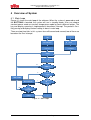
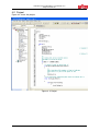
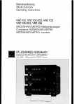
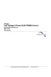
Fujitsu Microelectronics (Shanghai) Co., Ltd.
User Manual
Inductor Heater (Half Bridge)
Software
User Manual
Inductor Heater (Half Bridge) User Manual V1.0
Revision History
Revision History
Date
2010-04-06
2010-08-10
2010-11-17
Author
Kevin. Lin
Kevin. Lin
Kevin.Lin
Change of Records
V1.0.0, First draft
V1.1.0,update the main loop figure. Initialization value.
V1.1.1,update error code list
This manual contains 27 pages.
1. The products described in this manual and the specifications thereof may be changed without prior notice.
To obtain up-to-date information and/or specifications, contact your Fujitsu sales representative or Fujitsu
authorized dealer.
2. Fujitsu will not be liable for infringement of copyright, industrial property right, or other rights of a third party
caused by the use of information or drawings described in this manual.
3. The contents of this manual may not be transferred or copied without the express permission of Fujitsu.
4. The products contained in this manual are not intended for use with equipment which requires extremely
high reliability such as aerospace equipments, undersea repeaters, nuclear control systems or medical
equipments for life support.
5. Some of the products described in this manual may be strategic materials (or special technology) as defined
by the Foreign Exchange and Foreign Trade Control Law. In such cases, the products or portions thereof
must not be exported without permission as defined under the law.
© 2008 Fujitsu Microelectronics (Shanghai) Co., Ltd.
MCU-AN- 500077-E-10 – Page 2
Inductor Heater (Half Bridge) User Manual V1.0
Contents
Contents
REVISION HISTORY ................................................................................................. 2
1 PREFACE .............................................................................................................. 5
1.1
About This Book ...................................................................................................... 5
1.2
Reference Material .................................................................................................. 5
2 SYSTEM HARDWARE ENVIRONMENT ............................................................... 6
3 DEVELOP ENVIRONMENT .................................................................................. 7
4 OVERVIEW OF SYSTEM ...................................................................................... 8
4.1
Main Loop ............................................................................................................... 8
4.2
Project ..................................................................................................................... 9
5 FUNCTION DESCRIPTION ................................................................................. 10
5.1
Overview of the File ............................................................................................... 10
5.2
Initialization ........................................................................................................... 11
5.3
System Timer ........................................................................................................ 12
5.4
5.5
5.6
5.7
5.3.1
Function List ............................................................................................ 12
5.3.2
Function Prototype................................................................................... 12
Power Management .............................................................................................. 13
5.4.1
Function List ............................................................................................ 13
5.4.2
Function Prototype................................................................................... 13
Display and Key .................................................................................................... 15
5.5.1
Function List ............................................................................................ 15
5.5.2
Function Prototype................................................................................... 15
Protection .............................................................................................................. 18
5.6.1
Function List ............................................................................................ 18
5.6.2
Function Prototype................................................................................... 18
Others ................................................................................................................... 19
5.7.1
Function List ............................................................................................ 19
5.7.2
Function Prototype................................................................................... 19
6 IMPORTANT DETAILS ........................................................................................ 20
6.1
Initialization ........................................................................................................... 20
6.2
Power Adjustment ................................................................................................. 20
6.3
Pot Detection......................................................................................................... 21
6.4
Mode Switch .......................................................................................................... 21
6.5
Protection .............................................................................................................. 22
6.6
Key and display ..................................................................................................... 22
MCU-AN- 500077-E-10 – Page 3
Inductor Heater (Half Bridge) User Manual V1.0
Revision History
6.7
Important variable and flag .................................................................................... 23
7 ADDITIONAL INFORMATION ............................................................................. 24
8 APPENDIX........................................................................................................... 25
8.1
List of Figure ......................................................................................................... 25
8.2
List of Table........................................................................................................... 25
8.3
MCU Usage........................................................................................................... 26
8.4
ErrorCode.............................................................................................................. 27
MCU-AN- 500077-E-10 – Page 4
Inductor Heater (Half Bridge) User Manual V1.0
Chapter 1 Contents
1 Preface
1.1 About This Book
This book provides a detailed description of the half bridge inductor heater software.
The user could have an overlook to the structure of the code after reading this
manual. The software is developed based on MB95F430 serious MCU.
Table1.1 shows the summary of chapters included in this manual.
Chapter Title
Description
Preface
System hardware
environment
This chapter introduces the content of this book
This chapter introduces the MCU
Development environment
This chapter introduces the development tools
Overview of system
This chapter describes the main loop and project
Function description
This chapter describes the function list and prototype
Important details
This chapter explains some detail information
Additional Information
This chapter gives the website for this document
Appendix
This chapter gives the MCU pin usage and error code
Table 1. 1 Chapter Summary
1.2 Reference Material
Use this book in conjunction with:
•
Inductor Heater (Half Bridge) Demo Board User Manual v1.1.0
MCU-AN- 500077-E-10 – Page 5
Inductor Heater (Half Bridge) User Manual V1.0
Chapter 2 System Hardware Environment
2 System Hardware Environment
CPU Chip: Fujitsu MB95F434H;
CPU Frequency: 8MHZ;
Instruction Time: 0.25us;
Ram Space: 496Bytes;
Flash Space: 20KBytes;
MCU-AN- 500077-E-10 – Page 6
Inductor Heater (Half Bridge) User Manual V1.0
Chapter 3 Contents
3 Develop Environment
Name
Description
Manufacturer
Notes
Windows XP Pro
PC OS
Microsoft
SP2
Softune V3
Software Developing
IDE
Fujitsu
For FFMC-8L
MB95F434H
Emulator
MCU Emulator
Fujitsu
---
MCU-AN- 500077-E-10 – Page 7
Inductor Heater (Half Bridge) User Manual V1.0
Chapter 4 Overview of System
4 Overview of System
4.1 Main Loop
Figure 4.1 shows the main loop of the software. When the system is powered on and
the BUTTON6 is touched, the system will run in standby mode. User can choose
constant power mode or constant temperature mode by touch different button. The
key and display scanning is implemented in basetimer interrupt. The period is 2ms.
Key parsing and display content setting is done in main loop.
There are two time ticks in this system: four-millisecond and second, two of them are
based on the 2ms interrupt.
Figure 4. 1 Main Loop
MCU-AN- 500077-E-10 – Page 8
Inductor Heater (Half Bridge) User Manual V1.0
Chapter 4 Contents
4.2 Project
Figure 4.2 shows the project.
Figure 4. 2 Project
MCU-AN- 500077-E-10 – Page 9
Inductor Heater (Half Bridge) User Manual V1.0
Chapter 5 Function Description
5 Function Description
5.1 Overview of the File
Table 4.1 shows the files used in this project.
Function
Main Function
Initialization
Files
Description
IH.c
Main application code
general.h
Header file with extern definitions for main
function
def.h
Header file with macro definitions
mb95430.h
Header file with I/O and register definitions
InitMCU.c
Initialize
involved
all
modules
and
peripherals
def.h,mb95430.h As described ahead
System Timer
Power
Management
BaseTimer.c
Afford time tick for system
def.h
As described ahead
PowerOutput.c
The file contains running mode and power
adjustment functions.
poweroutput.h
Header file with function and variable
definitions for power management
def.h,mb95430.h As described ahead
Display and Key
DisplayandKey.c
The file with key parsing, display setting
and scanning interrupt functions.
displayandkey.h
Contains the BCD code ,function and
variable definitions used in displayandkey.c
def.h,mb95430.h As described ahead
Protection
Protect.c
Detect the protect resource and do protect
actions when illegal case occurs
def.h,mb95430.h As described ahead
Buzzer and Fan
Base Timer
System file
BuzzerandFan.c
Buzzer and fan will be controlled in this file
def.h,mb95430.h As described ahead
basetimer.c
time ticks
startup.asm
Start file
vector.c
Configure the vector priority and address
Table 4. 1 Related Files
MCU-AN- 500077-E-10 – Page 10
Inductor Heater (Half Bridge) User Manual V1.0
Chapter 5 Contents
5.2 Initialization
5.2.1
Function List
Prototype
Description
void InitMCU (void)
5.2.2
•
Initialize the modules and peripherals used in this
application
Function Prototype
void InitMCU(void)
Input:
void
Output:
void
Description:
Initialize the modules and peripherals used in this
application
Note:
These modules or peripherals will be initialized:
1. System clock
2. Ports
3. Buzzer
4. OCU and FRT
5. I2C module
6. ADC
7. Voltage comparators
8. Base timer
MCU-AN- 500077-E-10 – Page 11
Inductor Heater (Half Bridge) User Manual V1.0
Chapter 5 Function Description
5.3 System Timer
5.3.1 Function List
Prototype
Description
void System_Tick (void)
/
void BaseTimer_ms (void)
Afford four- millisecond tick to system
void BaseTimer_s (void)
Afford second tick to system
5.3.2 Function Prototype
• void System_Tick (void)
•
•
Input:
void
Output:
void
Description:
no
Note:
this function is called in main loop
void BaseTimer_ms (void)
Input:
void
Output:
void
Description:
generate millisecond tick
Note:
this function is called in System_Tick ()
void BaseTimer_s (void)
Input:
void
Output:
void
Description:
generate second tick
Note:
this function is called in System_Tick ()
MCU-AN- 500077-E-10 – Page 12
Inductor Heater (Half Bridge) User Manual V1.0
Chapter 5 Contents
5.4 Power Management
5.4.1 Function List
Prototype
Description
void PotDetect (void )
Detect the pot
void HeatTiming (void)
Kill the time of heat
void ConstantPowerMode (void)
Adjust the power level according to the setting
value, and keep the power output stable
void ConstantTempMode (void)
Adjust the power output according to the
temperature of the pot bottom, and keep it stable
void AdjustPower (void)
Keep the current stable
void StopOCUPro (void)
Stop the OCU output softly
void SetOCU (uchar Frequency)
Set the OCU frequency
uint ADC (uchar channel)
Get the voltage value on target channel
note : uchar is short of unsigned char, uint is short of unsigned int
5.4.2 Function Prototype
• void PotDetect (void)
•
•
Input:
void
Output:
void
Description:
Detect the pot
Note:
no
void HeatTiming (void)
Input:
void
Output:
void
Description:
Kill the time of heat
Note:
This function will shut down the system when the time is
out.
void ConstantPowerMode (void)
Input:
void
Output:
void
Description:
Adjust the power level according to the setting value, and
keep the power output stable
Note:
When the PowerLevel isn’t equal to PowerLevel_old, do
fast adjustment, then slight adjustment.
The range of power level is 0~8. 0---min power ,8 ---max
power
MCU-AN- 500077-E-10 – Page 13
Inductor Heater (Half Bridge) User Manual V1.0
Chapter 5 Function Description
•
•
•
void ConstantTempMode (void)
Input:
void
Output:
void
Description:
Adjust the power output time according to temperature of
the pot bottom, and keep it stable
Note:
The temperature can be set from 50 to 100 degree.
void AdjustPower (void)
Input:
void
Output:
void
Description:
Measure the current value and keep it stable
Note:
no
void StopOCUPro (void)
Input:
void
Output:
void
Description:
Stop the OCU output softly
Note:
To decrease the influence to power line when power off,
the system has to shut down step-by-step with power
level decrease.
•
•
void SetOCU (uchar Frequency)
Input:
void
Output:
void
Description:
Set the OCU frequency
Note:
when the frequency is 0, the OCU will stop with pins
cleared.
unsigned int ADC (uchar channel)
Input:
void
Output:
void
Description:
Get the voltage value on target channel.
Note:
no
MCU-AN- 500077-E-10 – Page 14
Inductor Heater (Half Bridge) User Manual V1.0
Chapter 5 Contents
5.5 Display and Key
5.5.1 Function List
Prototype
Description
void DoKey (void)
Parse the key value
void DisplaySetting (void)
Update the display content
void ErrorDisplay (void)
Display the error code
void NormalDisplay (void)
Display normal content
void ConfirmSetting (void)
Make a 5s delay before confirming the settings
uchar
*DECtoBCD
DecValue)
(uchar Convert decade code to BCD code
uchar
AT5088_Read
chip_id, uchar Addr)
(uchar Read given register of AT5088 through I2C
module
void
AT5088_Write
(uchar Write given register of AT5088 through I2C
chip_id, uchar Addr, uchar Data) module
5.5.2 Function Prototype
• void DoKey (void)
Input:
void
Output:
void
Description:
Parse the key value
Note:
This is the button definition and corresponding code below:
ON/OFF
--
0x40
TIMING
--
0x80
INCREASE
--
0x20
DECREASE
--
0x10
RIGHT
--
0x08
LEFT
--
0x04
CONST PWR
--
0x02
CONST TEMP
--
0x01
MCU-AN- 500077-E-10 – Page 15
Inductor Heater (Half Bridge) User Manual V1.0
Chapter 5 Function Description
•
•
•
•
•
void DisplaySetting (void)
Input:
void
Output:
void
Description:
Update the display content
Note:
Update the display content including error display and
normal display. If the error code is 0, normal display
routine will be executed; otherwise the error display
routine will be executed.
void ErrorDisplay (void)
Input:
void
Output:
void
Description:
Display the error code
Note:
This function is called in DisplaySetting ()
void NormalDisplay (void)
Input:
void
Output:
void
Description:
Display the normal content,
Note:
This function is called in DisplaySetting ()
void ConfirmSetting (void)
Input:
void
Output:
void
Description:
Make a 5s delay before confirming the settings
Note:
Each touch for setting will refresh the 5s counter. This
function is called in DoKey ().
uchar *DECtoBCD (uchar DecValue)
Input:
uchar DecValue
Output:
BCDCode [ ]
Description:
Convert decade code to BCD code
Note:
the max input decade value is 999.
MCU-AN- 500077-E-10 – Page 16
Inductor Heater (Half Bridge) User Manual V1.0
Chapter 5 Contents
•
•
uchar AT5088_Read (uchar chip_id, uchar Addr)
Input:
uchar chip_id, uchar Addr
Output:
uchar Button
Description:
Enable to read the given register of AT5088 through I2C
module
Note:
This function is called in TimerBase_ISR ()
void AT5088_Write (uchar chip_id, uchar Addr)
Input:
uchar chip_id, uchar Addr
Output:
void
Description:
Enable to write the given register of AT5088 through I2C
module
Note:
This function is called in TimerBase_ISR ()
MCU-AN- 500077-E-10 – Page 17
Inductor Heater (Half Bridge) User Manual V1.0
Chapter 5 Function Description
5.6 Protection
5.6.1 Function List
Prototype
Description
void Protect (void)
Get the protect resource inputs,
protection when illegal events occur.
and
do
5.6.2 Function Prototype
• void Protect (void)
Input:
void
Output:
void
Description:
Get the protect resource inputs, and do protection when
illegal events occur.
Note:
This function is called in main loop
MCU-AN- 500077-E-10 – Page 18
Inductor Heater (Half Bridge) User Manual V1.0
Chapter 5 Contents
5.7 Others
5.7.1 Function List
Prototype
Description
void FanCtrl (void)
Control the fan
void BuzzerCtrl (void)
Control the buzzer
5.7.2 Function Prototype
• void FanCtrl (void)
Input:
void
Output:
void
Description:
Control the fan
Note:
1. When the OCU is enabled, the fan will run.
2. When the OCU is disabled, the fan will go on running
for 1minute.
•
void BuzzerCtrl (void)
Input:
void
Output:
void
Description:
Control the buzzer
Note:
Each sound will last for 200 ms.
MCU-AN- 500077-E-10 – Page 19
Inductor Heater (Half Bridge) User Manual V1.0
Chapter 6 Important Details
6 Important Details
6.1 Initialization
Table 6.1shows the modules and peripherals used in this system and their initial
state.
Module or peripheral
Initial state
system clock
main osc clock = 8MHz, MCLK = 4MHz
output compare unit
CLK= MCLK , up-down mode, output disabled, buffer
enabled , HW_STOP enabled
free-run timer
clock = ¼ MCLK, up-down mode,
I2C bus
clock = MCLK, Fsck = 83K, interrupt mode
ADC
clock = ¼ MCLK, 10bit data format, start by AD bit
base timer
2ms
port
according to the function of the port
Table 6. 1 Initial State
The system is initialized to power off state with all display off.
6.2 Power Adjustment
The Induction Cooking board works on the principle of a series L-C resonant circuit.
When the size of L and C are set, the resonant frequency is set as well.
Unfortunately, this value does not depend only on the resonant tank. In fact, the size
and material of the pot affect the resonant frequency too. This causes the system to
have an oscillatory resonant frequency strongly depending on the type of pot placed
on the plate. So each power level does not work on a constant PWM frequency, but
a constant current.
In this system, the power adjustment includes two steps: fast adjustment and slight
adjustment. The fast adjustment is done per second before the real power level
equals to the target power level. The slight adjustment will be done after the fast
adjustment is completed.
MCU-AN- 500077-E-10 – Page 20
Inductor Heater (Half Bridge) User Manual V1.0
Chapter 6 Contents
6.3 Pot Detection
Actually, the inductor heater won’t heat if there is no pot on the heat plate, that is
protection act in fact. Before heating. the system will output a period of pulse
sequence and measuring the AC current. If there is a pot on the heat plate, the
current will be much higher than that there is no pot on the heat plate.
Figure 6.1 shows the flow of pot detection.
Figure 6. 1 Pot Detection
6.4 Mode Switch
This inductor heater has three modes: constant power, constant temperature and
timing. The two modes ahead are mutually exclusive. The timing mode can coexist
with one of others.
In constant power mode, the system will keep the power output stable.
In constant temperature mode, the system will keep the temperature of the pot
bottom stable.
If timing mode is selected, the system will run in constant power mode or constant
temperature mode until the time is out, then the system will enter standby
automatically.
MCU-AN- 500077-E-10 – Page 21
Inductor Heater (Half Bridge) User Manual V1.0
Chapter 6 Important Details
6.5 Protection
There are five kinds of protection for this system: over current, surge, over voltage,
IGBT over temperature, pot over temperature and pot removed protection.
Over current is implemented by comparator 1. it will monitor the resonant current
flowing the resonant tank. When over current occurs, the system will break for 30 s.
Surge is implemented by comparator 2. it will monitor the rectifier module output
voltage. When Surge occurs, the system will break for 30 s.
Over voltage protection will protect the system from high voltage (256VAC) or low
voltage (187VAC) input. If that happens, the system will stop and alarm. ADC
channel 0 is used to monitor the AC voltage.
IGBT over temperature is implemented ADC channel AN07. When the temperature
of IGBT is higher than 80 centigrade degree, the system will stop until the
temperature return to normal area.
If the temperature of pot bottom exceeds 200 centigrade degree. The pot over
temperature protection will take effect. the system will stop until the temperature
return to normal area.
If the pot is removed during heating, the OCU also will stop to protect the IGBT
stage.
The error code can be found in chapter 8 Appendix.
6.6 Key and display
The key and display function is mainly implemented using AT5088 that is a capacity
touch chip. It exchange the key and display data with MCU by hardware I2C bus.
The MCU will communicate with AT5088 once per 2ms. The user can found the
code in the file DisplayandKey.c .
MCU-AN- 500077-E-10 – Page 22
Inductor Heater (Half Bridge) User Manual V1.0
Chapter 6 Contents
6.7 Important variable and flag
Figure 6.2 shows the important variable and flag as below:
Variable or flag
Description
Mode
0--standby mode mode,1--constant power mode, 2-constant temperature mode
PowerLevel_new
power level that user can select. level 0~level 8
PowerLevel_new_buf
power level buffer for flicker display when setting. level
0~level 8
PowerLevel_old
the previous power level. level 0~level 8
PotTemp
Pot temperature that user can set. 50 ~100 degree
PotTempbuf
Pot temperature buffer for flicker display when setting
PotTempExt
the actual temperature of pot
Hour
the hour value that user can set. 0~1
Minute
the Minute value that user can set. 1~59
DisplayVaule[4]
the array contains display content
BCDCode[10]
BCD code for display
CrntArray[6]
Current value to corresponding to power level
PulseFreq[8]
base frequency of each power level
Flag1.ONorOFF
1--ON,0--OFF
Flag1. PotDetect
1--detect pot, 0-- don’t detect pot
Flag1.PotExt
1--pot exists, 0-- no pot
Table 6. 2 Important Variable and Flag
MCU-AN- 500077-E-10 – Page 23
Inductor Heater (Half Bridge) User Manual V1.0
Chapter 7 Additional Information
7 Additional Information
For more information on FUJITSU MICROELECTRONICS products, please visit the
following website at:
Simplified Chinese Version: http://www.fujitsu.com/cn/fmc/services/mcu/mb95430/
English Version: http://www.fujitsu.com/cn/fmc/en/services/mcu/mb95430/
MCU-AN- 500077-E-10 – Page 24
Inductor Heater (Half Bridge) User Manual V1.0
Chapter 8 Contents
8 Appendix
8.1 List of Figure
Figure 4. 1 Main Loop ............................................................................................................ 8
Figure 4. 2 Project.................................................................................................................. 9
Figure 6. 1 Pot Detection ..................................................................................................... 21
8.2 List of Table
Table 4. 1 Related Files ....................................................................................................... 10
Table 6. 1 Initial State .......................................................................................................... 20
Table 6. 2 Important Variable and Flag ................................................................................ 23
MCU-AN- 500077-E-10 – Page 25
Inductor Heater (Half Bridge) User Manual V1.0
Chapter 8 Appendix
8.3 MCU Usage
Pin Number
Pin Name
1
PG2/PPG0/X1A/OUT1
Sub clock
2
PG1/TRG0/ADTG/X0A
Sub clock
3
Vcc
Vcc
4
C
C
5
P60/OPAM_P
Fan
6
P61/OPAM_N
LED COM0
7
P62/OPAM_O
SYS_PW
8
P12/EC0/UI/DBG
DBG
9
P00/INT00/AN00
System voltage measuring
10
P01/INT01/AN01/BZ
Buzzer
11
P02/INT02/AN02/UCK
NULL
12
P03/INT03/AN03/UO
SDA for I2C
13
P04/INT04/AN04/UI
SCL for I2C
14
P05/INT05/AN05/TO0
System current measuring
15
P06/INT06/AN06/TO1
Plate temperature measuring
16
P07/INT07/AN07/EC0
IGBT temperature measuring
17
P70/CMP0_O/OUT0
IGBT driver H
18
P71/CMP0_P
LED COM2
19
P72/CMP0_N
LED COM3
20
P73/CMP1_O/OUT1
IGBT driver L
21
P74/CMP1_P
OC protection reference voltage
22
P75/CMP1_N
OC input
23
P76/CMP2_O/UCK
LED COM1
24
Function
Surge protection reference voltage
25
P64/CMP2_N
Surge input
26
P65/CMP3_O/UO
LED COM4
27
P66/CMP3_P
Short circuit protect reference voltage
28
P67/CMP3_N
Short circuit protect
29
PF2/RSTX
Reset
30
PF0/X0
oscillator
31
PF1/X1
oscillator
32
Vss
Vss
MCU-AN- 500077-E-10 – Page 26
Inductor Heater (Half Bridge) User Manual V1.0
Chapter 8 Contents
8.4 ErrorCode
Error Code
Description
Notes
E0
HW_STOP is set
E1
Low voltage
the power supply is lower
than 185V
E2
Over voltage
the power supply is higher
than 256V
E3
Pot temperature sensor is short
E4
Pot temperature sensor is open
E5
IGBT temperature sensor is short
E6
IGBT temperature sensor is open
E7
Pan over temperature
the temperature of pan
bottom is higher than 200 C
E8
IGBT over temperature
the temperature of IGBT is
higher than 80 C
MCU-AN- 500077-E-10 – Page 27