1
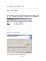
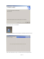
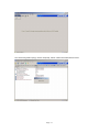
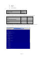
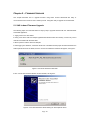
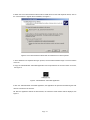
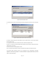
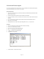
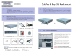
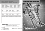
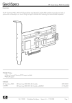
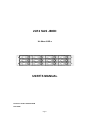
2U12 SAS JBOD XJ-SAxx-212R-x USER’S MANUAL Document number: MAN-00086-B P/N: NONE Page: i Important Information Warranty Our product is warranted against defects in materials and workmanship for a period of one year from the date of shipment, as evidenced by receipts or other documentation. The manufacture at its option, repair or replace equipment that proves to be defective during the warranty period. This warranty includes parts and labor. The media on which you receive software are warranted not to fail to execute programming instructions, due to defects in materials and workmanship, for a period of 90 days from date of shipment, as evidenced by receipts or other documentation. The manufacture will, at its option, repair or replace software media that do not execute programming instructions if the manufacture receives notice of such defects during the warranty period. The manufacture does not warrant that the operation of the software shall be uninterrupted or error free. National Instruments believes that the information in this document is accurate. The document has been carefully reviewed for technical accuracy. In the event that technical or typographical errors exist, the manufacture reserves the right to make changes to subsequent editions of this document without prior notice to holders of this edition. The reader should consult National Instruments if errors are suspected. In no event shall the manufacture be liable for any damages arising out of or related to this document or the information contained in it. EXCEPT AS SPECIFIED HEREIN, THE MANUFACTURER MAKES NO WARRANTIES, EXPRESS, IMPLIED, OR STATUTORY AND DISCLAIMS ANY IMPLIED WARRANTY OR CONDITION OF MERCHANTABILITY, FITNESS FOR A PARTICULAR PURPOSE, OR NON-INFRINGEMENT, OR A WARRANTY THAT THE PRODUCT WILL OPERATE ERROR FREE. IN NO EVENT SHALL THE MANUFACTURER BE LIABLE FOR THE COST OF PROCUREMENT OF SUBSTITUTE HARDWARE, SOFTWARE, OR SERVICES, LOST PROFITS, LOST DATA, OR ANY SPECIAL, INDIRECT, CONSEQUENTIAL, OR INCIDENTAL DAMAGES, HOWEVER CAUSED AND ON ANY THEORY OF LIABILITY ARISING IN ANY WAY OUT OF THIS AGREEMENT OR THE SERVER. THIS LIMITATION SHALL APPLY EVEN IF THE MANUFACTURER HAS BEEN ADVISED OF THE POSSIBILITY OF SUCH DAMAGES, AND NOTWITHSTANDING ANY FAILURE OF ESSENTIAL PURPOSE OF ANY LIMITED REMEDY PROVIDED HEREIN. This limitation of the liability of the manufacturer will apply regardless of the form of action, whether in contract or tort, including negligence. Any action against the manufacturer must be brought within one year after the cause of action accrues. The manufacture shall not be liable Page: ii for any delay in performance due to causes beyond its reasonable control. The warranty provided herein does not cover damages, defects, malfunctions, or service failures caused by owner’s failure to follow the manufacture installation, operation, or maintenance instructions; owner’s modification of the product; owner’s abuse, misuse, or negligent acts; and power failure or surges, fire, flood, accident, actions of third parties, or other events outside reasonable control. Copyright Under the copyright laws, this publication may not be reproduced or transmitted in any form, electronic or mechanical, including photocopying, recording, storing in an information retrieval system, or translating, in whole or in part, without the prior written consent of the manufacture. Trademarks Product and company names mentioned herein are trademarks or trade names of their respective companies. Changes The Manufacturer reserves the right to revise this publication and to make changes in the content hereof without the obligation of the manufacturer to notify any person of such revision or changes. FCC Compliance Statement This device complies with Part 15 of the FCC Rules. Operation is subject to the following two conditions: (1) This device may not cause harmful interference. (2) This device must accept any interference received, including interference that may cause undesired operation. Warning: • A shielded-type power cord is required in order to meet FCC emission limits and also to prevent interference to the nearby radio and television reception. It is essential that only the supplied power cord be used. • Use only shielded cables to connect I/O devices to this equipment. • You are cautioned that changes or modifications not expressly approved by the party responsible for compliance could void your authority to operate the equipment. Page: iii SAFETY PRECAUTIONS Before getting started, please read the following important cautions: All cautions and warnings on the equipment or in the manuals should be noted. Most electronic components are sensitive to electrical static discharge, therefore, be sure to ground yourself at all times when installing the internal components. Use a grounding wrist strap and place all electronic components in static-shielded devices. Grounding wrist straps can be purchased in any electronic supply store. Do not open the system’s top cover. If opening the cover for maintenance is a must, only a trained technician should do so. Integrated circuits on computer boards are sensitive to static electricity. Before handling a board or integrated circuit, touch an unpainted portion of the system unit chassis for a few seconds. This will help to discharge any static electricity on your body. Place this equipment on a reliable surface when install. A drop or fall could cause injury. Please keep this equipment from away humidity. Do not leave this equipment in an environment unconditioned, out of operation or storage temperature range may damage the equipment. Never pour any liquid into ventilation openings. This could cause fire or electrical shock. Make sure the voltage of the power source is within the specification on the label when connecting the equipment to the power outlet. The current load and output power of loads shall be within the specification. This equipment must be connected to reliable grounding before using. Place the power cord out of the way of foot traffic. Do not place anything over the power cord. The power cord must be rated for the product, voltage and current marked on the product’s electrical ratings label. The voltage and current rating of the cord should be greater than the voltage and current rating marked on the product. If the equipment is not used for a long time, disconnect the equipment from mains to avoid being damaged by transient over-voltage. Never open the equipment. For safety reasons, only qualified service personnel should open the equipment. If one of the following situations arise, the equipment should be checked by service personnel: 9 The power cord or plug is damaged. 9 Liquid has penetrated the equipment. 9 The equipment has been exposed to moisture. 9 The equipment does not work well or will not work according to its user‘s manual. Page: iv 9 The equipment has been dropped and/or damaged. 9 The equipment has obvious signs of breakage. 9 Please disconnect this equipment from the AC outlet before cleaning. Do not use liquid or detergent for cleaning. The use of a moisture sheet or cloth is recommended for cleaning. Product features and specifications are subject to change without notice. Page: v Table of Contents CHAPTER 1 – INTRODUCTION .....................................................................1 1.1 Key Features .................................................................................................................................. 1 Form Factor .......................................................................................................................................1 SAS Host Connections.....................................................................................................................2 Drive Features ...................................................................................................................................2 Firmware Upgrade Features ...........................................................................................................2 Environment Monitoring ...................................................................................................................2 Other Information ..............................................................................................................................2 1.2 Unpacking the Subsystem ......................................................................................................... 3 1.3 Front Panel Features ................................................................................................................... 5 1.4 Rear Panel Features..................................................................................................................... 6 Power Supplies & IO Module ..........................................................................................................6 RS-232 Serial Port ............................................................................................................................6 CHAPTER 2 – COMPONENTS SPECIFICATIONS ........................................7 2.1 Power supply specifications...................................................................................................... 7 2.2 Fans specifications ...................................................................................................................... 7 CHAPTER 3 – HARDWARE SETUP...............................................................8 3.1 Removing/Installing Disk Drives............................................................................................... 8 Installing a Disk into the Drive Canister .........................................................................................9 3.2 Connecting the JBOD to a Host.............................................................................................. 10 Single JBOD Configuration............................................................................................................10 JBOD Cascading Configuration....................................................................................................10 3.3 Powering on the JBOD .............................................................................................................. 11 3.4 Turning off the JBOD ................................................................................................................. 11 3.5 Restarting the JBOD .................................................................................................................. 12 3.6 Replacing a Power Supply ....................................................................................................... 12 3.7 Replacing a Fan........................................................................................................................... 13 3.8 Removing/Installing IO Modules............................................................................................. 13 3.9 Installing Rear Brackets for Fixed Cabinet Mounting........................................................ 14 CHAPTER 4 – SOFTWARE APPLICATION .................................................15 4.1 SAS Product Manager ............................................................................................................... 15 4.2 Hardware Fault Alarm ................................................................................................................ 18 Page: vi CHAPTER 5 – FIRMWARE UPGRADE ........................................................20 5.1 SAS In-band Firmware Upgrade ............................................................................................. 20 5.2 Out-of-band Firmware Upgrade .............................................................................................. 23 GLOSSARY...................................................................................................26 Page: vii CHAPTER 1 – INTRODUCTION The 2U 12-Bay SAS (Serial Attached SCSI) JBOD (Just a Bunch Of Disks) is a high performance, high density, scalable SAS to SAS/SATA (Serial ATA) Disk Expansion Enclosure. The unit can be cascaded from a SAS server or SAS DAS (Direct Attached Storage) through expander for maximum storage expansion. The JBOD is made up of several modules including one or dual IO modules with intelligent environmental monitoring, hot swappable backplane board, power supplies, fans, LED indications on the front panel, and hot swappable hard drive canisters. Single Silver color Black color XJ-SA13-212R-S XJ-SA13-212R-B XJ-SA26-212R-S XJ-SA26-212R-B IO module Dual IO modules 1.1 Key Features z Rackmount 2U Form factor z Supports 12 hot-swap 3.5” SAS and SATA drives z Front LED indications z Supports one or dual (redundant) I/O modules z Each IO module supports three mini SAS 4x connectors, dual host ports and one Expansion port z In-band (Windows® only) or serial port Firmware Upgrade z Environmental Monitoring, SEP/SES Support z Redundant 2+1 and hot-swap blowers z Redundant 1+1 and hot-swap Power supplies 460W with PFC Form Factor z 2U (3.5” high) Rack-mount Page: 1 SAS Host Connections z Each IO module supports three mini SAS 4x connectors, dual host and one expansion connection z Dual host ports for high availability z Transfer speeds of up to 1,200 MB/s per port connection Drive Features z 12 hot-swap drive canisters z SAS and SATA drive interfaces supported z Cooling to support up to 15,000rpm drive speeds z LED indicators for hard drive status and unit faults Firmware Upgrade Features z In-band firmware upgrade application, for Windows® only z Serial port firmware upgrade, out-of-band via RS-232 terminal console Environment Monitoring z Key components and internal temperature of the unit are real time monitored, including fans, power supplies and IO module(s). z If any system fault event happened, system fault LED will light red, and the beep will sound. At that time, press the mute button on the front panel to turn off the LED and beep. z System fault LED will turn red and the beep will sound if overheating (greater or equal to 50。C). Other Information z Redundant 2+1 and hot-swap blowers z Redundant 1+1 and hot-swap Power supplies 460W with PFC z Dimensions (H x W x D) : 87 X 440 x 548 mm z Weight without disk drives:: 41 lb ( 18.5 kg) Page: 2 1.2 Unpacking the Subsystem Before removing the subsystem from the shipping carton, visually inspect the physical condition of the shipping carton. Exterior damage to the shipping carton may indicate that the contents of the carton are damaged. If any damage is found, do not remove the components; contact the dealer where the subsystem was purchased for further instructions. Before continuing, first unpack the subsystem and verify that the contents of the shipping carton are all there and in good condition. The package contains the following items: Item Description Quantity The Set (colors: black & silver, please indicate 1 1x specific color when purchasing devices.) 2 Single IO module 1x Drive canister module - default A (see 2.1), 3 12x packed separated Printed Quick Operation Guide with safety 4 1x precautions 5 User's manual and utilities in a CD 1x 6 regional Power cord (US or EU) 2x Page: 3 7 Serial cable, DB-9 to stereo mini jack 1x Screws for disk mounting to the drive canister 8 1 set (4x per drive, 6x as spare) Rear brackets for rack mounting with screws for 9 1 set the chassis and the rack If any of these items are missing or damaged, please contact your dealer or sales representative for assistance. OPTIONS Below optional items are sold separately, please contact with your dealer or sales representative if any demands. Item Description Quantity OPTION SAS host to JBOD connection cable, length 1m 1 1x (P/N:CBL-SAE-IPIF-1M), Infiniband to mini SAS 4x connector For single IO module models: 1x For dual IO modules models: 2x Optional length: 2M (P/N:CBL-SAE-IPIF-2M) OPTION * SAS JBOD to JBOD connection cable, length 2 n/a 1m (P/N:CBL-SAE-IPIP-1M) Mini SAS 4x connector to mini SAS 4x connector * ditto, length 2m (P/N:CBL-SAE-IPIP-2M) 1x OPTION 3 Second/ Dual IO Module (P/N:XT-IOM-J2SA-TW) 1x OPTION 4&5 20” Sliding Rail (P/N:FRR-FR20-TW-AR) or 28” Sliding Rail (P/N:FRR-FR28-TW-AR) Page: 4 1.3 Front Panel Features 1.3.2 Front view LED (From left to right) LED Description,LED color System Power (PWR) LED, bBlue color Blue On:: System is powered on Off:: System has no power System status (FAIL) LED, rRed color Red On:: if any system fault event happened, Fan Fail, Power Fail, I/O Module Fail, Overheat Off:: System normal HDD LED indicators LED NAME Color definition Behavior HDD Activity: Drive power/activity LED, Blue color BLUE On:once HDD is inserted (even HDD is not ready for operation) Flashing:Drive I/O activity Off:No drive installed in the drive canister HDD Fail: Drive failure LED, Red color RED On: drive failed, identified by expander/HBA Off: normal drive Page: 5 1.4 Rear Panel Features I/O connections for power, host, expansion, and RS-232 are located on the rear of the unit. Power on/off switch Power Supplies & IO Module Two power supplies are located at the rear of the subsystem. Plug in the AC cords. Use the ‘Power On/Off’ switch to turn on the JBOD. If a power supply fails to function or the power cord unplugged, the front Fail LED will turn red on and an alarm will sound. Pressing the ‘mute’ button on the front of the unit will immediate stop the alarm from sounding and turn off the FAIL LED. Green On:Power is on Blue Flashing:Normal Off:If a power supply fails to function or the Blue On (still) or Off:The IO module failed power cord unplugged z Redundant 1+1 & hot-swap Power supplies, dual AC input z Redundant 2+1 & hot-swap Cooling Fan z I/O Module:: Single or Dual (Redundant) z Red Mute button, to reset the alarm buzzer after any system fault event RS-232 Serial Port The JBOD has one RS-232 serial port per IO module for connection to the host for firmware upgrade and status monitoring. Page: 6 Chapter 2 – COMPONENTS SPECIFICATIONS 2.1 Power supply specifications Dimension:300 (D) x 101(W) x 84 (H) mm Input characteristics Voltage:90~264 VAC full range Frequency:47~63 Hz Input current:8.0A (RMS) for 115VAC ; 4.0A(RMS) for 230VAC Inrush current:60A Max. for 115 VAC ; 80A Max for 230 VAC Output characteristics Output current Output voltage Regulation Min.(A) Max.(A) Load line + 5V 3.5 30 ±5% ±1% +12V 2 32 ±5% ±1% - 5V 0.05 0.7 +5%/-10% ±1% -12V 0.05 0.7 +5%/-10% ±1% +3.3V 1.0 24 ±5% ±1% +5VSB 0.1 2.0 +6/-5% ±1% 2.2 Fans specifications 97 x 94x 33 mm Items Specifications Outline dimension 97 X 94 X 33 mm Bearing Precise ball bearing system Material Thermoplastic PBT flame/impeller/bobbin Rated Voltage 12 VDC Operating Voltage 10.2 ~ 13.8 VDC Rated Current 0.72 AMP Rated Power Consumption 8.6 W Page: 7 Rotational Speed 3600 RPM Air Delivery 30.5 CFM Rotational Direction Counter-clockwise viewed from front fan blade Chapter 3 – HARDWARE SETUP 3.1 Removing/Installing Disk Drives This section describes the drive canister features and gives instructions on installing/removing a hard drive. The canister has three options available, default shipped with A option. A For SAS and single-port SATA drives, P/N: N2-100-20131 B For dual-port SATA drives with the interposer boards C Dummy, drive non-attachable Compared to A and B, C has none screw holes on the bottom side. (P.S. The customer can purchase A or B while he needs to install the drive later.) NOTE: Without the interposer boards installed, for models of single IO module only, the single IO module must be at the primary position for SATA drives. Perform the following steps to remove a drive canister from the enclosure. 1) Release the canister handle by pressing the latch in the handle towards the left. Note: Ensure that the canister is orientated so that the drive is uppermost and the handle opens from the right and left. 2) Carefully pull the handle out to disconnect the canister and drive from the backplane. The handle is a cam Page: 8 mechanism that will make a safe connection and disconnection of the drive into or out of the JBOD. If a drive was running in the canister, wait at least 1 minute for the drive to spin down after disconnecting it from the unit before fully removing it from the enclosure. 3) Remove the canister and drive from the enclosure. When handling with a hard drive, ensure proper grounding to protect the drive from static electricity. Installing a Disk into the Drive Canister 1. Pull out the disk canister. If a disk drive pre-installed, removing the drive by unscrewing on the canister bottom side. 2. Unpack the hard drive. 3. Place the hard drive in the disk canister. 4. Install the four mounting screws to secure the drive in the disk canister. 5. Slide the canister, gently, all the way into the enclosure. 6. When the canister is fully home, close the handle - a click should be heard as the latch engages. The HDD status LED on the canister will light. 7. 8. The HDD power LED will turn green. If the HDD power LED does not turn green, check the following: a. Make sure the hard drive is in good condition. b. Reinsert the drive canister into the slot to ensure that there is a good connection. If the hard drive is not being accessed, the blue HDD activity LED will not illuminate. The LED blinks only when being accessed. 7 WARNING: Electrical static discharge (ESD) can damage your drive or other components without causing visible signs of physical damage. To provide ESD protection, ground yourself by touching any metal part of the subsystem chassis. Page: 9 3.2 Connecting the JBOD to a Host Single JBOD Configuration Server with a SAS HBA or SAS RAID card SFF8470 (infiniband) SFF8088 miniSAS 4x 26-pin for host A typical configuration is shown in the above Figure. Use the provided cable to connect the JBOD to a host system. JBOD Cascading Configuration 8-channel SAS controller 4x 4x 24X Exp 12 x 4x 8-channel SAS controller 4x 12 x 4x 24X Exp SAS Expander 4x To Daisy-Chain JBOD enclosure Optional cables can be purchased to connect multiple JBOD enclosures. See section 1.2. Page: 10 for JBOD Server with a SAS HBA or SAS RAID card SFF8470 (infiniband) SFF8088 miniSAS 4x 26-pin for host for JBOD For connecting JBOD to JBOD 3.3 Powering on the JBOD After drive installation is complete, connected to the Host server, the JBOD can be turned on. This should be done in the following order: 1. Ensure that the cable(s) between the host and JBOD are connected securely. 2. Plug in both power supplies to AC inlets. 3. Press the On/Off button located on the rear panel to turn the unit on. The blue power LED on the front panel will turn on. 4. Wait until the drives in the unit have come online. 5. Ensure the JBOD enclosure is powered up prior to powering on the Host server. Once the JBOD is running, refer to your SAS HBA or RAID card manual to configure the JBOD. 3.4 Turning off the JBOD When turning off the JBOD, first shut down the server, then power off the JBOD. Use the Power On/Off button located on the rear of the unit to power off the JBOD. Page: 11 3.5 Restarting the JBOD When restarting or rebooting the host system, the JBOD does not need to be reset or powered off. 3.6 Replacing a Power Supply The JBOD includes redundant, hot-swap power supply units (PSU). To insert or remove the power supplies, use the thumbscrew located on each power supply. Turn the thumbscrew counter-clockwise to release and clockwise to tighten. If a power supply fails to function or the power cord unplugged, the front Fail LED will turn red on and an alarm will sound. Pressing the ‘mute’ button on the front of the unit will immediate stop the alarm from sounding and turn off the FAIL LED. PSU #1 LED PSU#1 Thumbscrew AC Inlet PSU #1 PSU Fans AC Inlet PSU #2 PSU#2 Thumbscrew PSU #2 LED To remove and replace a failed power supply module: 1. Check the LED on the power supply to determine which one has failed. The power on Green LED would be in the “Off” state on the failed power supply module. 2. Disconnect the AC power cord. 3. Unlock the thumbscrew of the failed power supply. 4. Press the latch to the right to pull out the failed power supply module using the handle. 5. Insert a new working module. Push it back in until it is fully inserted and lock the thumbscrew. 6. Connect the AC power cord and turn on the AC power switch. CAUTION: To maintain proper airflow in the unit, do NOT remove a failed power unit until a replacement is readily available. Page: 12 3.7 Replacing a Fan The JBOD includes three redundant, hot-swap blower modules located at the rear of the unit. The JBOD does not have to be shutdown before replacing a blower. However, to maintain effective airflow to cool the JBOD, please install a working blower right after the failed blower is removed. If a blower fails to function, the front Fail LED will turn red on and an alarm will sound. Pressing the ‘mute’ button on the front of the unit will immediate stop the alarm from sounding and turn off the FAIL LED. Check the monitor utility, see section 3.2, to determine which blower has failed. 1. Unlock the thumbscrew(s) of the failed blower module. 2. Pull out the failed blower module. 3. Replace the blower with a new working module. Push the new module in until it is fully inserted, and lock the thumbscrew(s). 3.8 Removing/Installing IO Modules The XJ-SAxx-316R includes single or redundant, hot-swap SAS Expender I/O modules. For redundant I/O modules, in case one I/O module failed, it can be replaced without shutting down the JBOD. The blue LED on the IO module will flash once per one to two seconds to indicate normal operation. If the IO module failed, the blue will turn off, Warning: To maintain effective airflow to cool the JBOD, do not remove the expander IO module unless a replacement can be immediately added. Page: 13 1. Using two hands, the Unlock the thumbscrew(s) of the SAS Expander IO module. Grasp each handle between the thumbs. 2. Hold tight the handle to pull out of the enclosure. Installing IO Modules 1. Slide the module into the enclosure until it is fully inserted, and locks the thumbscrew(s). 2. For single IO module, it has to be located on the right, primary, location. 3.9 Installing Rear Brackets for Fixed Cabinet Mounting One pair of rear supporting brackets is provided for fix-mounting the JBOD into a standard 19” cabinet. Use the rear mounting brackets and screws provided with the JBOD to mount the unit to the back of the cabinet. Align the front mounting ears with the front cabinet holes and secure with the screws provided to mount the front of the JBOD to the cabinet. Please note that some cabinets might have different vertical mounting column design. The brackets provided are intended to work with various types of cabinets however special mounting brackets from the cabinet manufacturer might need to be used if the brackets supplied do not work. Page: 14 Chapter 4 – SOFTWARE APPLICATION This chapter describes how to administer and monitor the JBOD with the provided Windows® application – SAS Product Manager. 4.1 SAS Product Manager The following steps are recommended to install the provided the latest SAS Product Manager. Please note, previous version of SAS Product Manager is only required when you received an engineering sample with earlier expander chip version. Double click to execute the setup program. Click the “Next” button to select the default installation folder. Page: 15 Click the “Close” button to end installation. The “SAS Product Manager” shortcut will appear on the desktop, double click to launch. Select “File” and then select “Logon” to communicate with the SAS expander device. Page: 16 The “Discovering SAN Topology” window will prompt, wait for a while until all SAS devices found. Page: 17 Go to “Command Line Interface” to real time monitor the unit status. In case any failure event happened, the failed component will prompt. For example, “FAN1 failed” is shown as below. Please refer to the online help to learn the functions of SAS Product Manager. 4.2 Hardware Fault Alarm Critical hardware components are monitored. z system overheating z IO module fail Page: 18 z HDD fail z Fan fail z Power supply fail Fault event definition 1. system overheat 。 >= 50 C 2. fan fail <= 1000 RPM If any fault event happened, system FAIL LED on the front will light red, and the beep will sound. Fault event Fail LED red on Beep Fan fail Yes Yes HDD fail (Controlled by the host) No No Power supply fail or power cord unplug Yes Yes Overheat Yes Yes One IO module fail (for dual IO modules only) Yes Yes Press the mute button to turn off LED and beep. Run “SAS Product Manager”, see section 3.1. Go to “Command Line Interface”, type “tShowState” and press “Enter” to check status. Page: 19 Chapter 5 – FIRMWARE UPGRADE This chapter describes how to upgrade firmware using either In-band Windows® GUI utility or out-of-band RS-232 console via the x-modem protocol. Using GUI utility to upgrade is recommended. 5.1 SAS In-band Firmware Upgrade The following steps are recommended as a step-by-step to upgrade firmware with the “FWLOAD.EXE” executable application. 1. Apply power to the SAS JBOD. 2. Using a PC with a SAS Host Adapter (updated with latest firmware and drivers), connect only one IO module of the JBOD with the SAS cable. 3. Boot up the PC with the SAS Host Adapter. 4. After logging into Windows, if the SSP virtual PHY is enabled with the proper firmware loaded into the SAS Expander device of the JBOD, then the “Found new hardware” Windows will appear, see Figure 1. Figure1. SAS device detected in Windows 5. The “Found New Hardware Wizard” window will start, see Figure 2. Figure2. Found New Hardware Wizard looking for SAS Expander driver Page: 20 6. When the Found New Hardware Wizard asks to install drivers for the SAS Expander device, click on the “Cancel” button to bypass driver installation, see Figure 3. Figure3. Found New Hardware Wizard asks to install drivers for SAS Expander 7. Once Windows has completed the logon process, save the latest firmware image to a known location on the PC. 8. Copy the “FWLOAD.EXE” executable application from the provided CD to a known location on the PC, see Figure 4. Figure4. “FWLOAD.EXE” executable application 9. Run the “FWLOAD.EXE” executable application; the application will proceed with detecting the SAS devices connected to the Host PC. 10. After the application detects the SAS devices, the Firmware Loader window will be displayed, see Figure 5. Page: 21 Figure5. Firmware Loader window 11. Click the “Browse” button and locate the latest firmware image that was saved to the PC, see Figure 6. Figure6. Firmware Loader window with firmware selected 12. After the firmware image has been selected, click the “Update” button to start the SAS In-Band firmware update routine. 13. A progress bar will be shown to indicate the status of the firmware update routine. 14. After 1 to 2 minutes, the firmware update will be completed, and the Firmware Loader window will be displayed again, see Figure 5. 15. Close the Firmware Loader application window. 16. For continued proper operation, shutdown and restart the SAS JBOD, and restart the host PC. The firmware update procedure should now be completed with the “FWLOAD.EXE” executable application. If there are any questions, or if further information is required, please contact your local dealer or sales representative. Page: 22 5.2 Out-of-band Firmware Upgrade You can also upgrade firmware via the serial port. In case you failed the main firmware ROM during the FWLOAD.EXE upgrading, there is another way to upgrade. Perform Preliminaries: 1. Using a PC with a DB9 serial port, connect the IO module of the JBOD with the provided serial cable (DB9 to stereo mini jack). 3. To disconnect all the SAS connectors of the IO module is recommended. 4. For dual IO modules, the other IO module must be removed from the JBOD. Otherwise will fail upgrading. 5. If you ever failed firmware upgrade of the main ROM, close the Second ROM pins to set it on. 6. Apply power to the SAS JBOD. 7. Run Hyperterminal 6.3 or earlier version (with settings 9600, none, 8, 1, none) on the PC. Procedure: 1. Power on the JBOD (the IO module without SAS connectors connected) 2. boot from second ROM (backup firmware) 3. Press “Enter” Twice for the arrow signal comes out 4. arrow “--Æ” command line for the system ready 5. Æ stat 6. Æ fwupdate to start upgrading 7. To select Transfer – send file of the menu bar to check the current latest firmware Page: 23 8. To select the right firmware 9. To select “ XModem” protocol and click “Send” to transfer firmware 10. Start firmware upgrading Page: 24 11. After completely done firmware updating. Power off the JBOD 12. Power on the JBOD 13. Ensure the latest firmware updated Page: 25 GLOSSARY Ricer Card A card that plugs into the motherboard to provide a perpendicular extension of the bus. Adapter cards are then plugged into the riser instead of the motherboard, allowing a lower profile to the case. Most often used for desktop systems that sit under the monitor. 1U/2U A “U”, Rack Unit, is equal to 1.75" in height. One rack unit is commonly designated as "1U"; similarly, 2 rack units are "2U" and so on. HDD A hard disk drive (HDD), commonly referred to as a hard drive or hard disk. Hot Swap The ability to pull out a component from a system and plug in a new one while the power is still on and the unit is still operating. Redundant systems can be designed to swap drives, circuit boards, power supplies and virtually anything that is duplicated within the system. Redundant It is used to guard the primary system from failure by acting as a back up system. CD-ROM Short for Compact Disc-Read-Only Memory, a type of optical disk capable of storing large amounts of data. USB Universal Serial Bus is a serial bus standard to interface devices. USB supports Plug-and-Play installation and hot plugging. Page: 26