1
Numeric controlled indexing tables
Series NCxxxTBx
(with B&R Controller & Absolute Encoder)
Operating Instructions
We reserve the right to change the content of this documentation (without prior notification). The WEISS GmbH is not
responsible for technical and printing faults in this documentation and accepts no liability for damages that result
directly or indirectly from its delivery, provision or usage.
Windows and Windows NT are registered trademarks of Microsoft Corporation entered in the USA and/or other
countries.
Simatic, STEP7 and S7 are registered trademarks of Siemens AG.
The pictures of chapter 5.4 "Including the Profibus" are make with friendly permission of Siemens AG, Department
Automation&Drives, Nürnberg.
This documentation is protected by copyright. Copying (in whole or in part) is not permitted without prior written
permission of WEISS GmbH.
Status: April 2006
Copyright:
2
WEISS GmbH Sondermaschinentechnik
Siemensstraße 17
D-74722 Buchen / Odw.
Germany
Tel.: +49 /(0)6281/5208-0
Internet: www.weiss-gmbh.de
NC-ABS-MEN-ELEKTRO-042006.DOC 04-06
Table of contents
1. Safety Regulations ............................................................................................................... 4
1.1 Safety and application notes........................................................................................... 4
2. Technical Data...................................................................................................................... 6
2.1 General data ................................................................................................................... 6
3. Structure ............................................................................................................................... 8
3.1 Overview ......................................................................................................................... 8
3.2 Naming............................................................................................................................ 9
3.3 ACOPOS drive ................................................................................................................ 9
3.4 Controller......................................................................................................................... 9
3.5 Battery Replacement .................................................................................................... 11
3.6 Windows Operating Program........................................................................................ 12
3.7 Hand-held Display......................................................................................................... 12
4. ACOPOS drive.................................................................................................................... 13
4.1 Motor ............................................................................................................................. 13
4.2 Motor lines..................................................................................................................... 13
4.3 Machine Zero Position .................................................................................................. 13
4.4 Installation of the ACOPOS drive ................................................................................. 14
4.5 Indications ..................................................................................................................... 15
4.6 Power Mains Connection .............................................................................................. 15
4.7 External I/O ................................................................................................................... 16
4.8 Connection Diagram ..................................................................................................... 17
4.9 Secure Restart Inhibit ................................................................................................... 18
4.10 Schematics for E-Stop ................................................................................................ 19
4.11 Cable........................................................................................................................... 24
5. Description of the user interface......................................................................................... 27
5.1 Overview of Terminals .................................................................................................. 27
5.2 Terminal Description ..................................................................................................... 28
5.3 Timing diagram .............................................................................................................34
5.4 Including the Profibus ................................................................................................... 35
6. Hand-held Display .............................................................................................................. 41
6.1 Structure and operation ................................................................................................ 41
6.2 Input fields..................................................................................................................... 42
7. Windows Program .............................................................................................................. 43
7.1 Program Installation ...................................................................................................... 43
7.2 Operation of the program.............................................................................................. 45
8. Program example ............................................................................................................... 68
9. Error Codes and Troubleshooting ...................................................................................... 75
9.1 Error Codes................................................................................................................... 75
9.2 Error messages............................................................................................................. 75
9.3 Resetting Error Messages ............................................................................................ 76
9.4 List of the most frequent error reports .......................................................................... 76
10. Transport and Installation ................................................................................................. 77
10.1 Transport..................................................................................................................... 77
10.2 Installation ................................................................................................................... 77
11. Spare parts ....................................................................................................................... 78
11.1 Spare parts ................................................................................................................. 78
12. Disposal and Recycling .................................................................................................... 79
12.1 Disposal and Recycling .............................................................................................. 79
13. Appendix........................................................................................................................... 80
NC-ABS-MEN-ELEKTRO-042006.DOC 04-06
3
1. Safety Regulations
1.1 Safety and application notes
The operating instructions should be read carefully before initial operation!
The initial operation of the indexing table may only take place once the total system and control,
especially the safety system, comply with the Machine Guideline 98/37/EG!
Before adjustment or maintenance work the power supply to the motor
has to be switched off and the motor has to be protected against
re-start!
To protect the operators from crushing by the mechanical system
during normal operation, appropriate protective devices such as
protective grids, covers, light barriers or step sensors have to be
installed!
Any work such as transport, storage, installation, initial operation and service of the control system and the
mechanical system may only be performed by trained expert staff.
Trained expert staff consists of persons that have the appropriate qualifications and are familiar with
performing the aforementioned work and the operation of the product.
The national accident prevention regulations have to be adhered to.
The safety guidelines, connection descriptions in the technical data and the documentation are to be read
carefully before installation and commissioning must be observed.
Unauthorized removal of the required covers, inappropriate use and improper installation or operation can
cause bodily injuring and / or severe damage to the systems.
The installation and cooling of the systems has to be performed according to these specifications. The
control system (PLC and ACOPOS drive) has to be protected from improper usage. ACOPOS drive and PLC
contain electrostatically sensitive components that can easily be damaged by improper handling. Electrical
components may not be mechanically damaged or destroyed (possible health risk)!
WEISS systems comply with the currently valid VDE regulations. The VDE regulations also have to be taken
into account when the systems are modified or un-installed.
Notes concerning correct installation with regard to electromagnetic compatibility (EMC), e.g. shielding,
grounding and installation of cables, are included in this documentation. Adherence to the thresholds
required by the EMC legislation is the responsibility of the manufacturer of the system.
Unauthorized changes and the use of spare parts and add-on devices that are not recommended by the
manufacturer, may lead to injuries of persons and damage to the mechanics and control system.
Some components (motor, ACOPOS drive) may have hot surfaces during operation. The operating
temperatures may be > 60 °C (> 140 °F). Skin contact leads to burns.
4
NC-ABS-MEN-ELEKTRO-042006.DOC 04-06
It has to be ensured that the casing is properly connected with the ground potential (PE-busbar) before the
ACOPOS drives are switched on.
The ACOPOS drive are allowed to be operated directly on grounded, three-phase industrial mains (TN, TT
systems).
Control and power connections may be live even if the motor is standing still. Never remove or plug the
electrical connections of the system when they are live.
All pluggable connections should only be connected or disconnected when power is off!
Wait at least 5 minutes after the system has been switched off before touching live parts or disconnecting
connections. All supply voltages connected to the system have to be safely separated from the power mains.
Appropriate usage
This system is intended for industrial and professional plants and complies with current standards and
regulations. All information concerning technical data and the permitted conditions at the site of installation
has to be adhered to at all times. This system is a component to be installed in machines. The initial
operation (start of the appropriate use) in prohibited until it has been established that the machine complies
with the EMC Guideline 89/336/EWG and that the final product complies with the Machine Guideline
98/37/EG.
Transport and storage
The systems have to be protected from inappropriate exposure (mechanical load, temperature, humidity,
aggressive atmosphere) during transport and storage.
EMERGENCY-STOP:
The contact "Enable" at the ACOPOS drive (contact X1/9) is implemented as a "secure restart inhibit" to deactivate the system and prevent unexpected re-operation. This corresponds to Safety Category 3 according
to EN 954-1. In addition to preventing unexpected re-operation according to EN 1037, this safety installation
also provides the stop functions of the Categories 0 and 1 required by EN 60204-1.
This is described in a separate chapter in these operating instructions (Chapter 4.9). The instructions in the
chapter must be adhered to.
A wiring diagram is also provided in this document.
NC-ABS-MEN-ELEKTRO-042006.DOC 04-06
5
2. Technical Data
2.1 General data
2.1.1 ACOPOS drive:
NC150
Type :
Permitted temperature ranges:
Installation position:
Air humidity:
Mains input voltage:
Installed load:
Main Fuse:
Peak Current:
Continuous Current:
Starting current:
Switch-on interval:
Power loss at max. device
power without brake resistor:
EMC:
Low-voltage guideline:
Protection according to
IEC 60529:
C-UL-US listed:
Dimensions:
Weight:
NC220
NC320, NC500
ACOPOS: 8V1022.00-2
ACOPOS: 8V1045.00-2
ACOPOS: 8V1090.00-2
Storage: -25°C...+55°C (-13 °F … 131 °F)
Operation: 0°C...+40°C ( 32 °F … 104 °F)
vertical
5 to 95%, not condensing
3 x 400 VAC to 480VAC +-10%, 48Hz to 62Hz
mains filter according to EN 61800-3-A11 second environment
max. 3 kVA
max. 5 kVA
max. 10 kVA
10A time delay
16A time delay
16A time delay
14 Aeff
24 Aeff
24 Aeff
2.2 Aeff
4.4 Aeff
8.8 Aeff
4A
7A
7A
> 10 sec
< 120 W
< 180 W
< 200 W
According to EG Guideline 89/336/EWG
Applied harmonised standards:
EN 61800-3 (Noise resistance)
EN 550011, Class B (Noise emission)
According to EG Guideline 73/23/EWG
Applied harmonised standards:
EN60204.1 / VDE113
EN50178 / VDE160
IP 20
YES
Width: 70.5mm
Height: 375mm
Depth: 236mm
4.0 kg
4.1 kg
4.4 kg
2.1.2 Motor:
NC150
NC220
NC320
Type:
Permitted temperature
ranges:
Protection according to
IEC 60529:
8MSA3M.R0-I9
8MSA4M.R0V7
8MSA4X.R0-V7
C-UL-US listed:
Rated speed:
Stall-/Peak torque:
YES
6000 RPM
1.0 / 5.2 Nm
=> limit to 4.8Nm
4500 RPM
4.1 / 21.2 Nm
=> limit to 7Nm
4500 RPM
7.5 / 38.0 Nm
=> limit to 12Nm
4500 RPM
7.5 / 38.0 Nm
=> limit to 18Nm
Rated Power:
Weight:
Brake torque:
0.63kW
2.6 kg
4.0 Nm
1.93kW
6.3 kg
8.0 Nm
3.53kW
11.0 kg
8.0 Nm
3.4kw
11.0 kg
15.0Nm
6
Storage: -20°C...+60°C
Operation: -15°C...+40°C
IP 64
NC500
8MSA5M.R0-V6
( -4 °F … 140 °F)
( 5 °F … 104 °F)
NC-ABS-MEN-ELEKTRO-042006.DOC 04-06
2.1.3 Encoder:
Type:
Resolution:
HEIDENHAIN ROQ 425 EnDat
approx. 25 million increments at output shaft
2.2 Electrical connection:
24 Volt control voltage
Power input 24 Volt
Digital inputs
Digital outputs
Profibus
20...28V DC, residual ripple < 10 %
ACOPOS drive, PLC, Display: 1.3A typical / 2.1A max.
brake: 0.5A … 1.0A
please use fuse: 6A time delay
Level
LOW (0V... +4 V)
HIGH (+15V...+30 V)
Input current
approx. 4 mA at 24 V
Input filter
1ms
Load capacity
max. 0.5 A per output
Profibus DP, Slave, ≤12 Mbit, floating
NC-ABS-MEN-ELEKTRO-042006.DOC 04-06
7
3. Structure
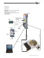
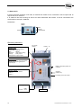
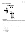
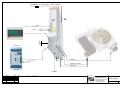
3.1 Overview
The system consists of the following modules:
- Mechanics
- ACOPOS drive 1022 / 1045 or 1090
- Cable set (W1 / W2 / W3 / W10 / W11 / W20)
- Option: Digital I/O
- Option: Display
mains connection
Inputs of the drive:
- Enable (Emergency-stop)
- Quick Stop
Option:
Display
- 24V supply
W11
563-200000017
563-200000015
or
563-200000016
digital outputs
Profibus
W10
W2
digital inputs
Motor line
Encoder line
Option:
Digital I/O
Encoder line
CAN-Bus
W3
W1
563-200000040…563-200000044
W20
8
563-100000020…563-100000024
RS232
563-200000020…563-200000024
563-200000010
NC-ABS-MEN-ELEKTRO-042006.DOC 04-06
3.2 Naming
NC
220
T
B
A
type
NC
transmission factor (ratio of reduction)
A = great ratio
B = small ratio
diameter
xxxx [mm]
encoder
A = incr. encoder (with reference)
B = absolute encoder
design
3.3 ACOPOS drive
The motor manufacturer provides a suitable drive for the control of the motor. The drive has his own
intelligence for the control of rotation, speed and position loop.
Three plug-in cards are inserted into the ACOPOS drive: controller (AC140) and encoder interface 1 & 2
(AC122 / AC120).
The ACOPOS drive communicates through the CAN Bus with separate digital I/O. The requirements for the
CAN Bus cabling have to be adhered to (terminating resistors at both ends of the CAN Bus).
Newest technique for emergency stops (quick stop ramp and also a secure restart inhibit (category 3)) are
integrated.
3.4 Controller
The controller (AC140) is a convenient interface between the customer interface and the ACOPOS drive. It
provides the required movement commands at the correct time and converts the preselected position values
of degree into motor increments.
The operation for standard tasks (indexing table with fixed graduation) is performed with a hand-held display.
A Windows Program is available to use the full scope of the software. It is connected to the controller
through a serial interface (RS-232). The RS-232 interface is also used for debugging and remote
maintenance through a modem or for visualisation. An OPC server for connecting professional visualisation
programs (WIN-CC, Wonderware, Intellution...) is also available. The following interfaces are supported in
addition: DDE server, HTML server und Intouch Fast-DDE.
Digital I/Os and a Profibus interface (Profibus DP, Slave, ≤12Mbit) are available as customer interfaces.
Other interfaces (CAN, RS232, RS485, Ethernet, etc.) are available on request.
The controller allows the following modes of operation:
- Jogging operation
- Teach zero position
- Move to fixed stations (graduation from 2...1500)
- Teach positions
- Move to position 1...127 (absolute or relative)
- 10 sequences with 40 commands each
- 8 freely programmable cams
- 8 trigger outputs
NC-ABS-MEN-ELEKTRO-042006.DOC 04-06
9
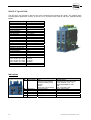
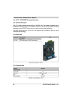
Slot PLC Type AC140:
The Slot PLC are mounted in the left slot of the ACOPOS drive (requires two slots). The module offers
interchangeable application memory in the form of a Compact Flash card as well as a separate backup
battery.
PLC
Processor Clock
SRAM
DRAM
Application Interface IF1
Interface Type
Electrical Isolation
Design
Max. Baud Rate
Indications
Application Interface IF2
Interface Type
Electrical Isolation
Design
Max. Baud Rate
Indications
Bus Termination Resistor
Application Interface IF3
Interface Type
Electrical Isolation
Design
Controller
RAM
Max. Baud Rate
Bus Lengths up to 100m
Bus Lengths up to 200m
Bus Lengths up to 400m
Indications
Bus Termination Resistor
100MHz
32kB
8MB
RS232
No
9-pin DSUB plug
115,2 kBaud
X1 LED
CAN
YES
9-pin DSUB plug
500 kBit/s (up to 60m)
RX / TX LED's
extern
Profibus DP
YES
9-pin DSUB socket
ASIC SPC3
1,5 kByte
12 Mbit/s
1,5 Mbit/s
500 kBit/s
RX / TX LED's
extern
Indications
Image
LED Description
Status (RUN)
RS232 (X1)
Profibus (RX)
Profibus (TX)
CAN (RX)
CAN (TX)
10
Color
Description
Red
Red with orange blinking
Red/green blinking (1Hz)
Orange
Green
Green with orange blinking
Orange blinking
Orange
Orange
Orange
Orange
ERROR/RESET
Load/unload and start BOOT AR
Startup of BOOT or CF – AR
SERVICE/DIAG/BOOT mode
RUN
RUN – BATTERY LOW
RS232: Data transfer
Profibus: Receive data
Profibus: Send data
CAN: Receive data
CAN: Send data
NC-ABS-MEN-ELEKTRO-042006.DOC 04-06
3.5 Battery Replacement
The battery of the controller has to be replaced every 5 years to prevent data loss. The control computer
monitors the battery voltage and gives a warning (digital output) if the voltage drops.
The replacement of the battery may take place when the control computer is switched of or when the 24 V
supply voltage is on. In some countries changing batteries is not permitted if the operating voltage is on. The
data in RAM (stored positions, movement sequences, zero position...) are lost when the battery is removed
when the supply voltage is off! Save the data in advance (Windows Program => Store parameters).
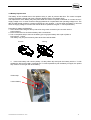
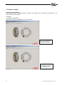
Procedure for battery replacement:
1. Drain electrostatic charge at the top-hat rail or the ground connection (do not reach into the
power supply!).
2. Remove the cover for the Lithium battery with a screwdriver.
3. Pull on the pullout strip to remove the battery (do not grip the battery with a pair of pliers or
bare pincers -> short).
The battery may only be touched by hand at the front and backside.
Correct:
Wrong:
4. Insert new battery with correct polarity. Lift the pullout strip and push the battery with the "+"-side
towards the left into the battery compartment. To make it possible to pull the battery out again, the pullout
strip must be on the right side of the battery.
Pullout strip
Lithium battery
NC-ABS-MEN-ELEKTRO-042006.DOC 04-06
11
5. Push the end of the pullout strip that stands out under the battery, so that it does not extend from the
battery compartment.
6. Replace the cover. The recess for the screwdriver should point upwards.
Lithium batteries are hazardous waste! Spent batteries have to be disposed of appropriately.
The battery has the type: CR2447N with a voltage of 3 V.
3.6 Windows Operating Program
The controller can be linked to a PC through a serial RS-232 interface. The Windows Program can be used
for easy configuration of the system. No permanent connection is required. The PC is only needed for the
initial operation. This is described in detail in Chapter 7.
3.7 Hand-held Display
An additional option for operating the system, in addition to using the Windows Program, is the connection of
a hand-held display. It provides the easiest form of operation and can be used to make adjustments and to
operate the indexer. The hand-held display is especially suited for beginners who want to use only a part of
the extensive functions.
12
NC-ABS-MEN-ELEKTRO-042006.DOC 04-06
4. ACOPOS drive
To ensure that motor and drive are optimally tuned, both parts are sourced from the same manufacturer.
The drive is part of the Series ACOPOS. Special attention was given to operational safety and extensive
monitoring functions.
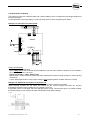
4.1 Motor
For the motors the model 8MSA with blocking brake, Resolver and smooth shaft end are used. These threephase synchronous motors are permanently excited, electronically commutated for applications that require
excellent dynamic characteristics and positioning precision.
4.2 Motor lines
The cable shield for the motor line is connected with the ACOPOS housing via the grounding plate using the
grounding clamp provided.
Please, pay attention to the correct reservation of the lines (U blue, V brown, W black).
4.3 Machine Zero Position
After the setting up and connection of the indexing table, you determine the machine zero position uniquely.
For this you move the axis via jog mode exact to this position where the angle should 0.0° be. This will be
normally the first processing stop. Then give the command "Set Zero" via the display, the Windows program
or via the digital Input. As a result, you see that the actual position changes to 0.000°. You must do this only
uniquely this after mounting the indexer. This offset is then stored in the battery RAM of the controller.
IMPORTANT: The machine zero position is invalid after you unmount the indexer or
the plate, if you disconnect the second encoder, if you change the ACOPOS drive or
if the battery is empty!
Note: Mark this place permanently (e.g. through red arrows or by a fit boring in the plate). So you can find
and re-teach the machine zero position fast after a repair.
NC-ABS-MEN-ELEKTRO-042006.DOC 04-06
13
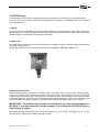
4.4 Installation of the ACOPOS drive
The ACOPOS drive may only be used in environments that comply with Pollution Level II (non-conductive
pollution). The maximum operating temperature of 40 ºC (104 °F)that is specified in the technical data, as
well as the protective system IP20 have to be taken into account when the system is installed.
A free space of at least 80 mm should be provided above and below the ACOPOS drive to ensure sufficient
air circulation.
14
NC-ABS-MEN-ELEKTRO-042006.DOC 04-06
4.5 Indications
Image
LED Description
READY
Color
green
RUN
orange
ERROR
red
Description
Lit when the ACOPOS drive is ready for operation (main
power and clamp X1/9 HIGH)
Lit when the axis is enable (hardware enable AND
software enable is HIGH)
Lit during POWER ON (boot procedure)
Lit if hardware enable clamp X1/9 if OFF (E-STOP)
Lit if an error at the ACOPOS drive exist
4.6 Power Mains Connection
The ACOPOS drive are allowed to be operated directly on grounded, three-phase industrial mains (TN, TT
systems).
The power mains connection is made using terminals X3 / L1, L2, L3 and PE. The permissible supply
voltage range for ACOPOS servo drive is 3 x 400VAC to 3 x 480 VAC ±10%. Always use at least 2.5mm² (or
AWG12) cabling. The grounding conductor has to have the same cross section.
Servo drives are systems with an increased discharge current (larger than 3.5mA AC or 10mA DC).
Therefore, a fixed (not mobile) protective grounding conductor is required on the servo drives.
Mains connection (Contact X3)
Fixed grounding connector
Mains fuse:
The power mains are to be equipped with over current protection in the form of a circuit breaker or a fuse.
Circuit breakers (time delay) with type C tripping characteristics (according to IEC 60898) or fuses (time
delay) with type gM tripping characteristics (according to IEC 60269-1) are to be used.
Fault current:
Servo drives have an internal power rectifier. If a short-circuit to the frame occurs, a flat DC fault current can
be created which prevents an AC current or pulse current sensitive RCD (Type A or AC) from being
activated, therefore canceling the protective function for all connected devices.
Fault current protection with a rated fault current of > 100mA can be used. For example, the AC-DC
sensitive, 4 pole fault current protective device F 804 from ABB (fault current: 300mA; nominal current: 63A)
can be used.
NC-ABS-MEN-ELEKTRO-042006.DOC 04-06
15
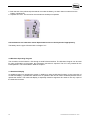
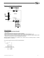
4.7 External I/O
If the bus interface (Profibus) is not used, an external I/O module can be connected. It has 16 inputs and 16
outputs with 24 V / 250 mA.
It is suited for DIN rail mounting as well as for direct attachment with screws. It can be connected to the
ACOPOS drive through a CAN Bus.
Dimensions:
Depth:
60mm
80mm
DIN rail
170mm
Operating elements:
24V supply
outputs
Output 1..16
Status LED:
Green:
Normal operation
Green flash.: Start-up
Red:
RESET
Red flash.: node number wrong
Orange:
Faulty output
Orange flash.:Supply outputs
I/O Monitor:
The button "Select" switched between
display of the inputs (green) and
outputs (red).
Bridge: Terminating resistor for
CAN Bus
Rotary switch:
CAN Bus
(Cable W10)
Setting of the CAN address:
SW1: C
SW0: C
24V Supply of the I/O module
24V supply inputs
-> GND
'-'
'DC OK' -> +24V
16
Input 1..16
NC-ABS-MEN-ELEKTRO-042006.DOC 04-06
4.8 Connection Diagram
24V
There are different ways of wiring the connector X4a for supplying power to the motor brake:
Monitoring
NC-ABS-MEN-ELEKTRO-042006.DOC 04-06
Monitoring
17
4.9 Secure Restart Inhibit
The ACOPOS drive have a built-in secure restart inhibit to guarantee that the device is stopped securely and
to prevent it from restarting unexpectedly. It is designed to correspond to safety category 3 according EN
954-1.
In addition to preventing the device from restarting unexpectedly according to EN 1037, this safety function
also meets the requirements of EN 60204-1 regarding the stop function for categories 0 and 1. Both stop
functions require the supply to the machine drives to be switched off (immediately for category 0 and after
stopping for category 1).
The restart inhibit interrupts the supply to the motor by preventing the pulse to the IGBTs. In this way, a
rotating field can no longer be created in synchronous and asynchronous motors.
For this function please use clamp X1/9 at the front side of the ACOPOS drive. Clamp X1/10 is the GND.
Clamp X1/9 / X1/10 is galvanic isolated from 24 V supply.
Take note that multiple errors in the IGBT bridge can cause a short
advancing movement. The maximum rotary angle φ of the motor shaft
that can occur during the jerking movement depends on the motor used.
It is approximately 60° at the motor shaft and 0.6° at the indexer plate.
We emphasize that the integrated "secure restart inhibit" does not interrupt the voltage supply to the motor. It
prevents only the build-up of a rotating field and prevents thus the start-up of the motor. If electrical work is
performed on the motor, the mains power supply had to be interrupted with a mains contactor or a main
switch.
Please note that at least 5 minutes discharging time for DC-bus should be provided before any electrical
work is performed. When the LED’s at the ACOPOS drive go off, this is not an indication that the voltages
are switched off and that the DC-bus has been discharged to below 42 V!
In case of a fault of the IGBT bridge, a life-threatening DC voltage may
be generated at the motor. In case of work on the motor, the mains have
to be disconnected through a mains contactor or a main switch.
Selecting the suitable safety category must be done separately for each indexer (for each servo drive) based
on a risk evaluation. This risk evaluation is a part of the total risk evaluation for the machine.
On the delivered CD-ROM, you find the manual of the drive manufacturer as soon as the TÜV Certificate
File: "ACOPOS_men_V131_04_2004.pdf", "SecureRestartInhibitTÜVCertificate_8V1180.00-2.pdf"
In the manual, you find further information in the chapter 1.3 "secure restart closure".
18
NC-ABS-MEN-ELEKTRO-042006.DOC 04-06
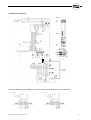
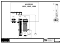
4.10 Schematics for E-Stop
The customer must put the indexing table into a safety category which corresponds to the danger potential of
the entire machine.
For the interruption of energy supply in case of E-Stop, there are three examples given below:
Example 1a: Interrupt of the main power
L1
L2
L3
PE
K1
COM (5-7, 13-15)
COM (5-7, 13-15)
4
2
1
3
L3
PE
L1
L2
4
3
X4a
X4b
X5
W
PE
18
Slot 1 Slot 2 Slot 3 Slot 4
Encoder
Resolver
PLC
AC120
AC122
AC140
T
M
3 ~
1
17
GND
+24V
COM (5-7, 13-15)
2
16
U
V
14
15
3
13
+24V
COM (8, 9)
COM (8, 9)
n.c.
n.c.
24V OUT
+24V
4
12
B+
BT+
T-
11
1
10
2
9
K2
3
8
K1
4
7
ACOPOS
S3
S4
S1
S2
6
COM (1, 2)
Shield
Limit switch +
Limit switch Reference switch
Enable
Enable
1
5
2
4
3
3
E-Stop
X3
X2
Trigger 1
Quickstop
4
2
24V
2
-DC1
-DC1
X1
1
+DC2
+DC2
1
K2
T
Safety considerations:
size main contactor sufficiently
Open clamp X1/9 at the ACOPOS drive simultaneous with the main contactor. Because of time overlap a
error (“main power low“) can occur.
- Switch-on interval: > 10sec. Please note!
- Wait at least 5 minutes after the system has been switched off before touching live parts or disconnecting
connections.
- A quick start (required when using a light curtain) is not possible (please consider switch-on interval).
-
Example 1b: Additional interruption of the brake line
Example 1a switches off the brake only when the hardware and the software is working.
When inserting contacts into the brake line (clamp 4a) the current through the brake can become
intermittent. Because of time overlap an error (“brake“) can occur.
If the brake is worn or has failed, the motor will take longer to stop. The axis then spins out. Please consider
this during design of your machine and the classification into a safety category.
Monitoring
NC-ABS-MEN-ELEKTRO-042006.DOC 04-06
19
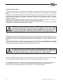
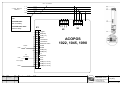
Example 2a: Interrupt of the motor lines
18
COM (5-7, 13-15)
COM (5-7, 13-15)
4
2
1
3
L3
PE
4
3
2
X4a
X4b
X5
W
PE
17
Slot 1 Slot 2 Slot 3 Slot 4
Encoder
PLC
Resolver
AC120
AC140
AC122
1
16
GND
24V OUT
+24V
+24V
COM (5-7, 13-15)
2
14
15
U
V
13
+24V
COM (8, 9)
COM (8, 9)
n.c.
3
n.c.
12
4
11
Enable
Enable
B+
BT+
T-
10
1
9
K2
2
8
K1
3
7
ACOPOS
Limit switch Reference switch
4
6
1
E-Stop
COM (1, 2)
Shield
Limit switch +
S3
S4
S1
S2
5
2
4
3
3
X3
X2
Trigger 1
Quickstop
4
2
24V
L1
L2
X1
1
+DC2
+DC2
-DC1
-DC1
1
L1
L2
L3
PE
K1
K2
T
M
3 ~
T
Safety considerations:
- size main contactor sufficiently
- Open clamp X1/9 at the ACOPOS drive simultaneous with the main contactor. Because of time overlap a
error (“motor phase“) can occur. If the clamp X1/9 is not opened a defect in the ACOPOS drive can occur.
An opening of the clamp X1/9 takes care besides of the contacts of the contactor since the ACOPOS drive
is disabled before opening the contacts and the motor current is interrupted (switching the contacts without
power).
- A quick start (required when using a light curtain) is possible.
Example 2b: Additional interruption of the brake line
As shown in example 1b, the current through the break can be interrupted.
If the brake is worn or has failed, the motor will take longer to stop. The axis then spins out. Please consider
this during design of your machine and the classification into a safety category.
Monitoring
20
NC-ABS-MEN-ELEKTRO-042006.DOC 04-06
Example 3a: Interrupt clamp X1/9 at ACOPOS drive
4
2
3
L3
PE
1
L1
L2
4
X4b
X5
W
PE
X4a
T
M
3 ~
1
18
2
17
Slot 1 Slot 2 Slot 3 Slot 4
Encoder
Resolver
PLC
AC120
AC122
AC140
3
16
GND
+24V
+24V
COM (5-7, 13-15)
COM (5-7, 13-15)
COM (5-7, 13-15)
U
V
14
4
13
15
B+
BT+
T-
12
+24V
1
9
11
2
8
10
3
7
ACOPOS
4
6
S3
S4
S1
S2
E-Stop
COM (1, 2)
Shield
Limit switch +
Limt switch Reference switch
Enable
Enable
COM (8, 9)
COM (8, 9)
n.c.
n.c. OUT
24V
1
5
2
4
3
3
X3
X2
Trigger 1
Quickstop
4
2
24V
3
1
-DC1
-DC1
X1
1
+DC2
+DC2
2
L1
L2
L3
PE
T
Safety considerations:
Please see chapter 4.9 (secure restart inhibit)
For frequent switching (no switch-on interval)
Wear resistant
A quick start (required when using a light curtain) is possible.
Meets the requirements 3 of EN 954-1 (secure restart inhibit, safety category 0, 1, 2)
Motor clamps (U, V, W) can also lead tension after shutdown (of clamp X1/9). Electric works on the
indexer are not allowed. You have to interrupt the main power.
-
You’ll find further information in the ACOPOS user’s manual (see File “ACOPOS_men.pdf“ on added
CDROM) chapter 5.1.2, page 126.
The current through the brake can still be interrupted besides:
Monitoring
NC-ABS-MEN-ELEKTRO-042006.DOC 04-06
21
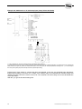
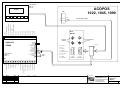
Example 3b: Additional use of Quickstop Input (clamp X1/2 at ACOPOS)
24V
n.c.
1.) The contactors K2 / K3 must correspond to the respective safety category.
3.) ACOPOS drives without 24VDC output (ACOPOS 1022/1045/1090), must be supplied externally. An interrupt of the 24V will stop the
brake and the axis spin out (and/or the mechanical brake in the motor fails). An error (temperature, following error, ..) or an interrupt at
the main power (clamp X3) also interrupts the active (electrical) braking.
Pressing the E_Stop switch S1 causes relay K2 to be released. In this way, the ACOPOS input “Quickstop”
triggers active braking. If the drive, etc. is faulty, then auxiliary relay K3 is released after a defined delay and
causes the energy feed to the motor to be cut off. The customer has set the delay time to the calculated time
of the stop ramp.
With this, you got the shortest braking time.
22
NC-ABS-MEN-ELEKTRO-042006.DOC 04-06
The customer has configure the input “Quickstop“ via the Windows Program (NR_indexer_BR.exe).
The limit values (deceleration ramp) describes the stop ramp.
The customer must carry out and check these settings independently (after every change in
settings).
He can use the oscilloscope function in the software.
This is to be considered especially, if a light curtain is used.
For Quickstop use clamp X1/2 at the front side of the ACOPOS drive. Clamp X1/3 is GND.
NC-ABS-MEN-ELEKTRO-042006.DOC 04-06
23
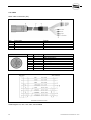
4.11 Cable
Motor cable construction (W1):
Item
1
2
3
4
Description
Motor lines
Circular connector
Shrink wrap
Wire tip sleeve
Circular connector
Remark
4 x 1.5 mm² + 2 x 2 x 0.75 mm²
BSTA 108 FR 19 08 0006 000
Pin
1
4
3
2
A
B
C
D
Description
U
V
W
PE
T+
TB+
B-
Function
Motor connection U
Motor connection V
Motor connection W
Protective ground conductor
Temperature sensor
Temperature sensor
Brake +
Brake -
Cable lengths: 5m, 10m, 15m, 20m, 25m available
24
NC-ABS-MEN-ELEKTRO-042006.DOC 04-06
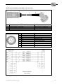
Structure of the Resolver cable (W2 / motor encoder):
Item
Description
Remark
1
2
3
4
Encoder cable
Circular connector, 12-pin socket
DSUB-housing 45°, 9-pin plug
Shrink wrap
3 x 2 x 0.25 mm²
ASTA 021 FR 11 10 0005 000
Circular connector
Pin
Description
1
2
3
4
5
6
7
8
9
10
11
12
----Cos
Sin
Ref
--Cos\
Sin\
Ref\
-------
NC-ABS-MEN-ELEKTRO-042006.DOC 04-06
Function
Cosinus input
Sinus input
Reference output
Cosinus input inverted
Sinus input inverted
Reference output inverted
25
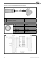
Structure of the encoder cable (W3) (to Heidenhain Encoder):
Item
Description
Remark
1
2
3
4
Encoder cable
Circular connector, 17-pin socket
DSUB-housing 45°, 15-pin plug
Shrink wrap
5 x 2 x0,25mm² + 2 x 0,5mm²
ASTA 035 FR 11 12 0005 000
Circular connector
Pin
Description
Function
15
10
12
7
14
8
16
4
13
1
17
9
A
COM (1, 3-9, 11, 13-15)
B
+5V out / 0.25A
D
T
/A
Sensing COM
/B
Sensing +5V
/D
/T
Channel A
Encoder supply 0V
Channel B
Encoder supply +5V
Data input
Clock output
Channel A inverted
Sense input 0V
Channel B inverted
Sense input +5V
Data inverted
Clock output inverted
blue
26
(0,25 mm²)
red
(0,25 mm²)
white
(0,25 mm²)
green
(0,25 mm²)
black
(0,25 mm²)
gray-pink
(0,25 mm²)
brown
(0,25 mm²)
pink
(0,25 mm²)
yellow
(0,25 mm²)
gray
(0,25 mm²)
violet
(0,25 mm²)
red-blue
(0,25 mm²)
NC-ABS-MEN-ELEKTRO-042006.DOC 04-06
5. Description of the user interface
The digital interface is described first. The Profibus interface is built in a similar way, but offers the option to
transmit numerical values (nominal position, actual position, fault number...).
5.1 Overview of Terminals
Inputs:
Terminal on
I/O-extension
(CX408)
Function
Remark
X1-1
X1-2
X1-3
X1-4
X1-5
X1-6
X1-7
X1-8
X1-9
X1-10
X1-11
X1-12
X1-13
X1-14
X1-15
X1-16
X1-17
X1-18
GND (0V)
+24V / DC_OK
E 1.1
E 1.2
E 1.3
E 1.4
E 1.5
E 1.6
E 1.7
E 1.8
E 1.9
E 1.10
E 1.11
E 1.12
E 1.13
E 1.14
E 1.15
E 1.16
24V-supply of the inputs
24V-supply of the inputs
Parameterise through Windows Program
Parameterise through Windows Program
Parameterise through Windows Program
Parameterise through Windows Program
Parameterise through Windows Program
Parameterise through Windows Program
Parameterise through Windows Program
Parameterise through Windows Program
Parameterise through Windows Program
Parameterise through Windows Program
Parameterise through Windows Program
Parameterise through Windows Program
Parameterise through Windows Program
Parameterise through Windows Program
Parameterise through Windows Program
Parameterise through Windows Program
Terminal on
I/O-extension
(CX408)
Function
Remark
X2-1
X2-2
X2-3
X2-4
X2-5
X2-6
X2-7
X2-8
X2-9
X2-10
X2-11
X2-12
X2-13
X2-14
X2-15
X2-16
X2-17
X2-18
GND (0V)
+24V
A 1.1
A 1.2
A 1.3
A 1.4
A 1.5
A 1.6
A 1.7
A 1.8
A 1.9
A 1.10
A 1.11
A 1.12
A 1.13
A 1.14
A 1.15
A 1.16
24V-supply of the outputs
24V-supply of the outputs
Parameterise through Windows Program
Parameterise through Windows Program
Parameterise through Windows Program
Parameterise through Windows Program
Parameterise through Windows Program
Parameterise through Windows Program
Parameterise through Windows Program
Parameterise through Windows Program
Parameterise through Windows Program
Parameterise through Windows Program
Parameterise through Windows Program
Parameterise through Windows Program
Parameterise through Windows Program
Parameterise through Windows Program
Parameterise through Windows Program
Parameterise through Windows Program
Outputs:
NC-ABS-MEN-ELEKTRO-042006.DOC 04-06
27
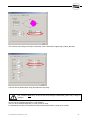
5.2 Terminal Description
The terminal allocation can be freely configured through the Windows Program. As there are more functions
than input terminals, a selection must be made.
To allocate terminals, the dialog box below is called from the Windows Program with: "Options->HW_Config>I/O_Config…". To set the parameters for a digital input/output, an entry such as "E1.1" or "A1.1" is required.
To allocate functions on the Profibus an entry such as "Bit 1" is required.
Profibus and digital I/Os can be mixed as required.
Example: Use of digital I/Os:
28
NC-ABS-MEN-ELEKTRO-042006.DOC 04-06
Inputs:
ENABLE (must be connected by the user)
At HIGH level the output stage of the ACOPOS drive is enabled, at LOW it is blocked.
This enable signal (software enable) is AND-linked with the contact X/19 on the ACOPOS drive. The motor
can therefore also be disabled from the customer PLC. The contact X1/9 (at the ACOPOS drive) is intended
for connection to the EMERGENCY-Stop circuit.
The following has to be taken into account for door circuits: The ACOPOS drives are only switched off if the
output "Disable" is HIGH. Only then, the lock of the doors may be opened.
The input "Enable" on the PLC alone does not meet the requirements of the
regulations for EMERGENCY-Stop and door circuits, as it requires a
functioning link (CAN Bus) between PLC and the ACOPOS drive, functioning
software and functioning connection to the output. To obtain the full
EMERGENCY-Stop functionality, the contact X1/9 at the ACOPOS drive or the
power supply of the ACOPOS drive has to be interrupted.
If you do not require software enable input, you can simply ignore this function (I/O_Config: write "---").
Enable is then only via the hardware input (clamp X1/9) possible.
That can be helpful if you use only Profibus interface and you want running the indexer the first time by using
the jog mode (without pro bus master).
Some customers want to block the indexer after a step. During the customer time (load/unloading the
indexer) they want to block the indexer to avoid unintentional movements. For this the "STOP" input is better
because the position controller is switched off if you disable the axis. When the position loop is open the
indexer lost his position.
Bit_A..Bit_G: Coding of commands
At these inputs the position or sequence numbers for the following commands are provided:
- Jog to Pos No. xxx
- Move to Pos No. (CW, CCW, abs, rel) xxx
- Start Sequence No. xxx
- Store Pos. No. xxx
Numerical values between 0 and 127 can be provided. This number is read when there is an rising edge in
one of the above signals.
The numbers are provided in binary form.
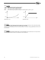
e.g. Position Number 2:
0000010
e.g. Position Number 3:
0000011
e.g. Position Number 12:
0001100
e.g. Position Number 45:
0101101
e.g. Position Number 83:
1010011
These Inputs are also used for the commands “JOG“ and “STEP“.
In the hardware configuration (Menu: HW_Config) of the Windows Program, these functions (Bit_A..Bit_G)
are assigned to the corresponding input terminals. If the 127 possible positions are not required, only the
required functions (Bit_A..Bit_G) have to be assigned. Unassigned functions are automatically set to "0".
NC-ABS-MEN-ELEKTRO-042006.DOC 04-06
29
Move to Pos CW (abs)
At an rising edge at this input, the indexer moves to the absolute position number that is provided at the
inputs Bit_A..Bit_G. The direction of rotation is right (CW). This signal normally starts a positioning process.
The signal is closely associated with the output "Ready to Start". As soon as this output is HIGH, the signal
"Move to Pos" is accepted. As soon as this command is accepted, the output "Ready to Start" goes LOW.
Now the "Move to Pos" input must become LOW. As soon as the axis has reached the position window, the
output "Ready to Start" goes HIGH again and a new start-command can be accepted (see timing diagram at
the end of the chapter).
The position number 0 has a special function. The user has therefore positions 1..127 freely available. For
each of these 127 positions an individual speed override can be set through the Windows Program. These
preset values are then multiplied with the general speed override (0..100%).
If an invalid position number is provided or the position has not yet been teached, an error message occurs.
Special function:
A reference run is started by providing the Position Number 0 and the command “Move to Pos“
(only for indexer without an absolute encoder).
-
Move to Pos CCW (abs)
As above, direction of rotation is left (CCW).
Move to Pos (abs)
As above. The direction of rotation is selected to ensure that the axis moves the shortest way.
Move to Pos (rel)
This command is similar to the command above. However, the position values teached are here interpreted
as relative values. The position number 0 is here invalid.
Example:
Current position:
45.0°
Teached position:
10.0°
=> The axis moves to 55.0°
Move to Pos CW (Bus)
Like the command "Move to Pos CW (abs)", but no teached position number is used. The target position and
the maximum speed are provided on the Profibus.
Move to Pos CCW (Bus)
As above, direction of rotation is left (CCW).
Move to Pos (Bus)
As above. The direction of rotation is selected to ensure that the axis moves the shortest way.
Special function: If you set the three inputs (“Move to Pos CW (Bus)”, “Move to Pos CCW (Bus)”, “Move to
Pos (Bus)”) together to HIGH, the position in the Profibus telegram is interpreted as a relative position.
Sequence
With the rising edge, the Sequence No.xxx (the number is binary coded on the Inputs Bit_A..Bit_G) starts.
Only after all commands have been completed, the output "Ready to Start" goes HIGH again. This function
is otherwise identical with "Move to Pos". Sequences with the numbers 1..10 are available. The commands
for the sequences are described in detail in the following chapter.
30
NC-ABS-MEN-ELEKTRO-042006.DOC 04-06
Step CW
This command produces one step of the indexing table in direction CW. The rotation angle depends on the
selected graduation (see dialog box "axis").
The inputs Bit_A..Bit_G have depending of the configuration “indexer steps” in the dialog box “axis” as
special function:
a.) mathematic calculated steps
The inputs Bit_A..Bit_G selected a position in the table “teached positions”. The position in the table is used
as an offset.
Example 1:
4 steps, Bit_A..Bit_G == 0
=> The indexer moves to the positions 0° / 90° / 180° / 270°
Example 2:
4 steps, Bit_A…Bit_G == 3
=> Position in the table no. 3 = 5.0°
=> The indexer moves to the positions 5° / 95° / 185° / 275°
Also the speed entry (override 0..100%) from the table is used.
b.) steps teached in the table
In the dialog box “axis” the initial value and the number of steps is defaulted. With the number, build by
Bit_A..Bit_G, the initial value is moved.
Example 1:
Bit_A..Bit_G == 0, 4 steps, initial value == 1
=> The positions no 1 / 2 / 3 / 4 from the table “stored
positions” are started.
Example 2:
Bit_A..Bit_G == 8, 4 steps, initial value == 1
=> The positions no 9 / 10 / 11 / 12 from the table “stored
positions” are started.
The offset from Bit_A..Bit_G is used to set an offset in case of an product alternation, or to set different
speeds (position entry in the table = 0.0°). Normal these inputs (Bit_A..Bit_G) are LOW.
Step CCW
As above, only rotation direction CCW
Toggle
This input is valid only if you define two steps (dialog boxes "axis"). With each rising edge the indexer toggle
between position no. 1 and position no. 2 (direction changes left/right)
Jog CW
As long as this input is HIGH, the indexer moves with jogging speed in direction CW.
The inputs Bit_A..Bit_G defines an override for the speed. The override is taken from the table “stored
position”. But normally these inputs are LOW.
Jog CCW
As long as this input is HIGH, the indexer moves with jogging speed in direction CCW.
Inputs Bit_A..Bit_G as above.
Jog to Pos
The indexer moves with jogging speed to the provided position number (Bit_A..Bit_G), i.e. the axis moves
first slowly and then increasingly faster. If the signal goes LOW, the indexer stops immediately, even if the
target position has not been reached. No completion message is provided when the position has been
reached. The signal is only used for the startup operation and is not intended for permanent operation. The
position number 0 (reference run) is not valid.
Store Pos
With rising edge on this input the actual position is stored at the position number that is provided at the
inputs Bit_A to Bit_G. Position number 0 is not valid.
NC-ABS-MEN-ELEKTRO-042006.DOC 04-06
31
Alarm Reset
An rising edge (>20 ms) acknowledges all pending fault messages.
Alternatively, the faults can be acknowledged through the Windows Program or the hand-held display.
Zero-Pos
With an rising edge the actual position is set to 0.000° (axis is zeroed). This zero position is now used as
starting point for all movements. It is assumption that the axis is Enabelt.
Release brake
Can be used to open the brake manually. Requirement is the operating mode "Axis disabled".
Move to last Pos
With this command the indexer moves to the previous position, e.g. after opening the door circuits the axis is
slightly pulled off its position. The command can be used to reproduce the position the axis had before
opening the door circuits.
Demo sequence
An rising edge starts the demo sequence. It is used, for example, for the startup operation of the axis or for
demonstrate the functions.
The demo sequence must first defined in the Windows Program at the menu "Demo sequence". The
commands available are the same as for the normal sequence. The difference to the sequence is, that the
demo sequence works in an endless loop, i.e. after the last command it jumps automatically to the first
command. The sequence is stopped through the input "Stop" or through the Windows Program.
Stop
This command stops all started movements ("Move to Pos", "Sequence", "Demo-Sequence").
This command does not affect the jogging function.
Some customers requests, if movement is ended and he begins processing (e.g. loading / unloading the
indexer) that the indexer does not start unintentionally, and causes a crash (with high material damage). For
this, this stop input would be able to be used. It is also possible to remove the input "Enable" alternatively.
However, this would result that the position loop is disconnected and the position is not checked and correct
no more. An small drifting from the position away is to be found then (<0.1°).
The stop command is not intended for an Emergency-Stop. For this purpose, the input "Enable"
(clamp X1/9 at the ACOPOS drive) must used.
Parameter 2
This is used to switch to the Parameter Set 2, which is defined in the dialog box "axis". It includes values for
speed, start ramp, stop ramp and jogging operation.
Search Home
Because using an absolute encoder, this input is not used.
32
NC-ABS-MEN-ELEKTRO-042006.DOC 04-06
Outputs:
Amplifier enabled
As soon as the ACOPOS drive has been switched on with the Input “Enable”, this signal goes HIGH. This
signal is not protected against cable breakage, i.e. if the signal goes LOW it cannot be concluded that the
indexer cannot move anymore.
Amplifier disabled
As soon as the Input "Enable" goes LOW and all movements have stopped, this signal goes HIGH to
indicate that the doors can now be unlocked.
Reference OK
This output indicates that a valid reference point is provided. Only then, the moving commands “Move to
Pos“, “Start Sequence“ and “Store Pos“ can be executed. (Only relevant for indexer without an absolute
encoder).
Ready to Start
This output indicates that the ACOPOS drive is ready to accept a new start command.
Error
This output indicates that an error has occurred.
Error (flash)
This output can be used to connect a light that flashes in case of an error.
Battery_Warning
If this output goes HIGH, it indicates that the battery should be exchanged.
Trigger_A1..Trigger_B4
These outputs can be set from a sequence. Trigger_A: These outputs are automatically reset after a
sequence has been completed or terminated (e.g. error message or door circuit opened). The outputs of the
group Trigger_B are retained, until they are reset by a command.
Cams 1...8
A maximum of 8 cams can be defined through the Windows Program. These are the corresponding outputs.
InPos
This output indicates that the axis has reached the target position of the last movement command. It is
comparable to a cam, for which the position is set to the target position for every movement command. The
size of the cam is set in the dialog box "axis" (Part 1, Input Field: "InPos").
NC-ABS-MEN-ELEKTRO-042006.DOC 04-06
33
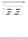
5.3 Timing diagram
Enable
Bit_A..Bit_G
pointer to dialogbox
"stored position" in
binary coded form
Input:
Move_to_Pos
Output:
Ready to Start
34
NC-ABS-MEN-ELEKTRO-042006.DOC 04-06
5.4 Including the Profibus
This chapter explained you, how to parameterise the Profibus interface.
Chapter 5.4.1 explains the works on the Profibus master side, that is on a Siemens S7 by using a S7-300.
Chapter 5.4.2 explains the parameterisation at the B&R ACOPOS drive.
Additional you can use the parameter channel. You'll find this docu in an own file at the CD ROM
"Profibus_Parameter_Channel_en.pdf"
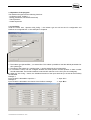
5.4.1 Parameterising the Profibus Master
1. Generate a new project. Here e.g. with a S7-300 PLC.
Remark: If you have only a few stations, a baud rate from 1.5Mbits/s satisfies. As a result, you have the same reaction time as in the
case of 12Mbits/s. In this way, you can even achieve advantages in the case of a bad line quality.
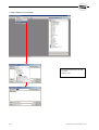
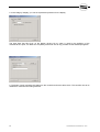
2. Install new GSE file:
Remark:
If a GSE file is already referenced, you must at first close
all stations in order to be able to import the GSE file. After
the import of the GSE file you open the stations again.
NC-ABS-MEN-ELEKTRO-042006.DOC 04-06
35
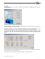
3. Select GSE file from CD ROM
Rem.:
You’ll find the GSE file at the CD ROM
in the folder:
“Profibus / Ac14x“
36
NC-ABS-MEN-ELEKTRO-042006.DOC 04-06
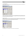
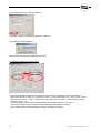
4. Now find in the hardware catalog under “PROFIBUS DP / Additional Field Devices / PLC“
the imported file for the Profibus interface “AC140”.
Mark it and drag it to the Profibus master system by pressing the left mouse key.
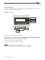
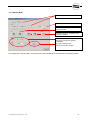
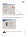
5. Now a dialog box is opened, where you can set the slave address.
These address must be agree with the switches at the front of the slot PLC (AC140) in the ACOPOS drive.
Rem.: You can change the address later at any time.
Profibus address at the slot PLC
“AC140“ (ACOPOS drive)
LED for
receive / sending
address:
HIGH - Byte
LOW – Byte
Read in only after
power ON.
Profibus
plug
NC-ABS-MEN-ELEKTRO-042006.DOC 04-06
37
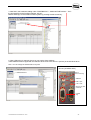
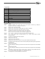
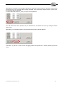
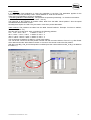
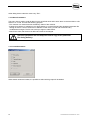
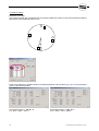
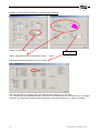
6. Now define the inputs and outputs:
In this example, 2Byte inputs (16Bit) and 2Byte outputs (16Bit) are defined. The S7 software allocate a free
I/O address. You can change it each time.
Rem.: If you want to send the actual- and nominal positions of the axis in addition to the 16 bit inputs and
outputs, choose a telegram length of 10Byte.
Mark the corresponding module and
drag it into the left table.
To get data consistency please use
“Universal module”
The S7 software allocate a free
I/O address.
Here in this example:
I0.0 ... I1.8 and Q0.0 ... Q1.8
38
NC-ABS-MEN-ELEKTRO-042006.DOC 04-06
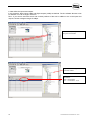
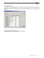
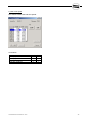
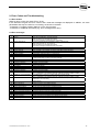
5.4.2 Parameterisation of the B&R ACOPOS drive
If the Profibus is used, the Profibus message can be configured. It can be determined if only the digital
inputs and outputs (Chapter 5.2) should be send, or if the nominal and actual positions should be send as
well. The additional information increases the length of the Profibus message (from 2 Bytes to 10 Bytes).
Select whether the nominal position
and the nominal speed should be
send as well.
Display of the new message length.
The shown text “modul_02e“ or “modul_10e“
corresponds to the configuration selection in the
Profibus-S7 Master-System.
The same applies to the send message.
NC-ABS-MEN-ELEKTRO-042006.DOC 04-06
39
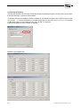
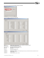
The Profibus message is structured as follows:
Receive:
Byte 0
Byte 1
Byte 2
Byte 3
Byte 4
Byte 5
Byte 6
Byte 7
Byte 8
Byte 9
Byte 0: Digital inputs Bit 0... Bit15 (Chapter 5.2)
Byte 1: Digital inputs Bit16...Bit31 (Chapter 5.2)
Byte 2: Reserve
Byte 3: Reserve
Byte 4: Nominal position (LO-Byte)
Byte 5: Nominal position
Byte 6: Nominal position
Byte 7: Nominal position (HI-Byte)
Byte 8: Nominal speed (LO-Byte)
Byte 9: Nominal speed (HI-Byte)
Remark:
- Nominal position: This is the nominal position to which the axis moves when the command “Move to Pos
Bus“ is executed. The nominal position is standardised to 0.001°, i.e. a numerical value of 90000 is
interpreted as 90.000°. The valid numerical range is 0..359999 (0..359.999°).
The byte order was selected to allow direct mapping of the 32-bit numerical value to a Bit Memory Double
Word (MDW) or a double word in a Data Block (e.g. DB7.DBD100). Re-sorting of the byte order of the 32bit value in the Siemens S7 is not required.
- Nominal speed: The speed (0..100%) for the command “Move to Pos Bus“ is set here. The value is
standardised to 0.01%, i.e. a numerical value of 10000 is interpreted as 100.00%
Send:
Byte 0
Byte 1
Byte 2
Byte 3
Byte 4
Byte 5
Byte 6
Byte 7
Byte 8
Byte 9
Byte 0: Digital outputs Bit0... Bit15 (Chapter 5.2)
Byte 1: Digital outputs Bit16...Bit31 (Chapter 5.2)
Byte 2: Reserve
Byte 3: Reserve
Byte 4: Actual position (LO-Byte)
Byte 5: Actual position
Byte 6: Actual position
Byte 7: Actual position (HI-Byte)
Byte 8: Fault No. (LO-Byte)
Byte 9: Fault No. (HI-Byte)
Remark:
- Actual position: The value for the actual position is standardised to 0.001°, i.e. a numerical value of 90000
is interpreted as 90.000°.
40
NC-ABS-MEN-ELEKTRO-042006.DOC 04-06
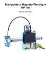
6. Hand-held Display
It is possible to operate the indexer from a hand-held display for simple applications. To achieve the full
functionality, the Windows Program has to be used.
6.1 Structure and operation
Page number
NC Indexer V 0.2.3
Page:023
Value field
4500
maximum speed
Remark
Quit
alarm
Increase/
decrease value
Page to
screen
Enter button
The buttons F5 / F6 are used to page between screens.
The buttons F3 / F4 ("+" / "-" buttons) are used to increase/decrease a numeric value. During this process
the value field flashes. The value is first written into an intermediate buffer and then accepted with the button
F2 ("Enter" button). After acceptance, the value field stops blinking.
The button F1 is used to acknowledge error messages.
You’ll find a summary of the error codes below in chapter 9.
Brightness:
Brightness can be switched darkly by pressing the buttons "F2" and "F3" together.
Brightness can be switched lightly by pressing the buttons "F2" and "F4" together.
NC-ABS-MEN-ELEKTRO-042006.DOC 04-06
41
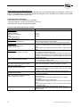
6.2 Input fields
Screen No.
1
2
3
4
11
12
13
15
20
21
22
23
24
25
26
30
Function
Operating message (only display)
Alarm message (only display)
Actual position (only display)
Cycle time (only display)
Set zero position
Jogging operation
Step (manual operation)
Start demo sequence
Indexer type
Indexer graduation
Mass inertia of the load
Max. speed
Start-ramp
Stop-ramp
External brake resistor
Select language
Description in detail:
Page 1:
Operating message: The current state of the control system is shown (e.g. "Ready for
Operation", "Motor turns", "Waiting for Command"...).
Page 2:
Display of the current fault message
Page 3:
Display of the current position (rotating angle of the indexer in degrees)
Page 4:
Display of the movement time of the last movement command
Page 11:
The button F2 sets the current position to 0.000° (zero calibration).
Button F3 and F4 can be used to move the indexer in jogging mode.
Page 12:
The "+" and the "-" button can be used to move the indexer in jogging mode.
Page 13:
The "+" button starts a step in clockwise direction. The "-" button starts a step in counterclockwise direction.
Page 15:
The button F2 starts/stops the demo sequence
Page 20:
Setting of the indexer type
Page 21:
Setting of the indexer graduation
Page 22:
Setting of the mass inertia of the load. This may result in different start/stop ramps.
Page 23:
The maximum motor speed can be set here. Note: By defining the indexer type the upper limit is
automatically set.
Page 24:
Setting of the start ramp
Note: By defining the indexer type as well as the mass inertia, the upper limit is automatically
set.
Page 25:
Setting of the stop ramp
Note: By defining the indexer type as well as the mass inertia, the upper limit is automatically
set.
Page 26:
Configuration: External brake resistor present (yes/no). Switching is only possible when the
drive has been disabled (axis disabled, e.g. by Emergency-Off, etc.).
Page 30:
The language of the hand-held display can be set here.
42
NC-ABS-MEN-ELEKTRO-042006.DOC 04-06
7. Windows Program
7.1 Program Installation
The programs were developed in Microsoft Visual Studio and require an up to date computer for installation
(Windows 95 or newer, Internet Explorer 5.5 or newer, due to the installed drivers).
Please make sure to read the Readme file on the CD-ROM.
Procedure:
The installation of the Windows Program is performed in two steps:
- Installation of the PVI monitor for communication between the ACOPOS drive and the Windows computer
- Installation of the program "NC_Indexer_BR.EXE"
Installation of the PVI monitor:
On the supplied CD-ROM in the directory "PVI_Eng" start the file "Setup.exe".
NC-ABS-MEN-ELEKTRO-042006.DOC 04-06
43
Installation of the Windows Program:
On the CD-ROM in the directory "Win_Prog" start the file "setup.exe".
7.1.1 PVI Monitor
General:
The PVI monitor is used as a driver between the Windows Program and the ACOPOS drive. It is provided by
the manufacturer of the drive (B&R). The PVI monitor runs license-free for 2 hours. An error message will
appear when the two hours are exceeded. When "NC_Indexer_BR.EXE" is restarted, the program is ready
to run for another two hours.
Alternatively, a security key or a safety code is available.
The driver has a wide range of functions. It connects all kinds of serial interfaces of the PC with the
ACOPOS drive. PCMCIA adapters or USB adapters (USB to RS-232) can also be used. This is becoming
increasingly important for the operation with laptop computers. It is further possible to connect a modem into
the RS-232 line.
The connection cable is arranged as follows:
Pin 2
Pin 3
Pin 5
<-----> Pin 3
<-----> Pin 2
<-----> Pin 5
This cable is delivered with the CD-ROM.
During the installation of the PVI monitor, an OPC driver can be installed as well. It makes it possible to
connect the ACOPOS drive to professional visualisation programs (WinCC, Intellution, Wonderware...) to
achiever the same functionality that the program "NC_Indexer_BR.EXE" provides.
44
NC-ABS-MEN-ELEKTRO-042006.DOC 04-06
7.2 Operation of the program
The Windows Program has the following functions:
- Configuring (Axis, Profibus...)
- Debug (I/O-Monitor, Parameter download)
- Teach positions
- Create sequences
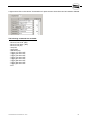
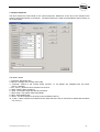
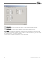
7.2.1 Configure
Under the menu item: "Options->HW_Config..." the indexer type as well as the I/O configuration and
Profibus are configured first => See example in Chapter 8
1. The indexer type (NC220TBA,...) is entered first. This makes it possible to load the default parameters for
this system type.
2. The name of the system (e.g. welding robot...) can be entered in the comment field.
3. If a Profibus is used, one can configure whether the actual position nominal position or alarm number
should transmitted. The Profibus address is set with DIP switches on the PLC (see circuit diagram).
4. Under the "I/O Config..." button, the individual functions of the input terminals (or the bits at the Profibus)
are allocated.
Example 1:
Input "Enable" is allocated to input No. 1:
=> Input: I1.1
Example 2:
Input "Enable" is allocated to the first bit of the Profibus message:
=> Input: Bit 1
NC-ABS-MEN-ELEKTRO-042006.DOC 04-06
45
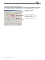
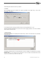
5. In the category "display" you can set a password protection for the display.
The input field "Set Zero Pos" on the display (picture No.11) which is used for the definition of the
mechanical zero point, can fades out completely so that set zero is only possible via the Windwosprogramm.
6. The button "Apply" transfers the settings to the controller and stores them there. The controller has to be
restarted to make the new setting effective.
46
NC-ABS-MEN-ELEKTRO-042006.DOC 04-06
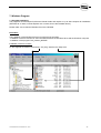
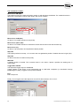
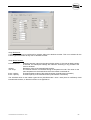
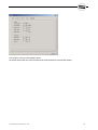
7.2.2 Debug
The functions "Restart PLC", "Set Date", "Logbook" and "I/O Monitor" are available under the menu item
"Options->Debug“.
The button "Set Date..." is used to set the PLC time and date to the current PC date. The PLC date is used
to attach a time stamp to each error message.
The button "I/O Monitor..." opens the I/O Monitor that displays the current states (HIGH/LOW) of the
individual input and output bits. The inputs and outputs can also be “forced” for startup purposes.
The frame around the inputs Bit_A..Bit_G and the input field is intended to make the representation of these
signals easier. The inputs Bit_A..Bit_G represent the numbers of the commands "Move_to_Pos" and
"Sequence" in binary form. The input field can be used to specify these values in the familiar decimal
system.
It is recommended to use the I/O Monitor during startup to control the wiring. If a bus system is used (e.g.
Profibus), its function can be checked as well.
On the right side, the inputs of the ACOPOS drive are shown. They cannot be forced.
NC-ABS-MEN-ELEKTRO-042006.DOC 04-06
47
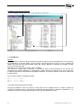
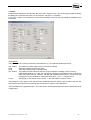
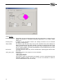
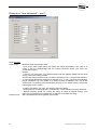
7.2.3 Teach Positions
After the hardware has been configured and the I/O interface has been tested with the I/O Monitor, the
individual positions are teached.
A total of 127 positions with the descriptions No.1...No.127 are available for teaching. The Position 0 has a
special meaning: If Position 0 is called, a reference run is triggered. This function is ignored by systems with
an absolute encoder (indexer types: NCxxxTBx).
Setting of the values:
The blue cursor is set to the position number that is to be teached. Thereafter, the axis is moved to the target
position with the keys "CW" and "CCW" (jogging operation). The actual positions are accepted into the input
field through a double-click when the blue cursor is at the column "Angle".
Double-clicking on one of these fields accepts the values of the actual position.
48
NC-ABS-MEN-ELEKTRO-042006.DOC 04-06
Alternatively, the position can be entered directly as numerical value (if known). It should be noted that the
numerical input is only accepted after pressing RETURN. If the input field is left with TAB or a mouse click,
the new input value is discarded.
For each individual position a v_max (0...100%) can be specified.
Once all values have been specified, they are transferred to and stored in the PLC by clicking the button
"PC
PLC“.
Alternatively, the individual positions can be teached through the customer interface.
The button "Jog to Pos“ is used to move in jogging mode to the position No. currently marked by the blue
cursor.
NC-ABS-MEN-ELEKTRO-042006.DOC 04-06
49
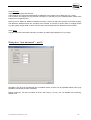
7.2.4 Adjust Sequences
At the menu entry “Program->Sequence...“ sequences can be stored. Sequences are started like
movements to individual positions, but instead of the command “Move to Pos“ the command “Start
Sequence“ is given. Up to 10 sequences can be stored. Each sequence can have a maximum of 40
commands.
1. Enter sequence No. (number between 1..10)
2. Specify commands 1..40. The commands are described below
3. Store sequence on the PLC (PC
PLC)
50
NC-ABS-MEN-ELEKTRO-042006.DOC 04-06
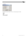
A right mouse click on the column "Commands xxx" opens a menu where lines can be inserted or deleted.
The following commands are available:
-
Move to Pos CW (abs)
Move to Pos CCW (abs)
Move to Pos optim. (abs)
Move to Pos (rel)
Step CW
Step CCW
Wait time (ms)
Trigger_A1=ON / OFF
Trigger_A2=ON / OFF
Trigger_A3=ON / OFF
Trigger_A4=ON / OFF
Trigger_B1=ON / OFF
Trigger_B2=ON / OFF
Trigger_B3=ON / OFF
Trigger_B4=ON / OFF
End
NC-ABS-MEN-ELEKTRO-042006.DOC 04-06
51
The commands in detail:
Move to Pos CW (abs)
The indexer moves to the teached position number xx with absolute coordinates. The rotation direction is
right (CW). The position number is the value in the column "Option".
Move to Pos CCW (abs)
As above. The rotation direction is left (CCW).
Move to Pos optim. (abs)
As above. The rotation direction is selected to ensure that the axis moves the shortest way.
Move to Pos (rel)
As above, only the position is interpreted as relative position.
Step CW
The indexer performs one step, i.e. it moves to the next graduation position. Rotation direction is right (CW).
Step CW
As above. Direction of rotation is left (CCW)
Wait time
A waiting period is inserted. The numerical value in the column "Option" specifies the waiting time in
milliseconds.
Trigger A/B ON/OFF
The respective trigger output is set/deleted.
Trigger outputs of the Group A are automatically set to LOW after completion (or termination through
fault/Emergency-Stop). Triggers of Group B are retained.
End
End of sequence.
Finally, do not forget to save the sequence on the PLC with the button "PC
PLC".
52
NC-ABS-MEN-ELEKTRO-042006.DOC 04-06
7.2.5 Demo Sequence
The demo sequence works similar to the normal sequence. Difference: At the end of the sequence the
system jumps automatically to command 1. The demo sequence is used for presentations and for startup, to
run-in the system.
The fields in detail:
1. Cycle time: Movement time.
2. Step No.: Displays the currently active step.
3. "Override": Refers to the overall speed override, i.e. all speeds are multiplied with this factor
(0.01%..100.00%).
4. "PC
PLC": Stores the demo sequence in the PLC.
5. "Start": Starts a demo sequence.
6. "Stop": The system stops after the last command.
7. "Quick Stop": The system stops immediately.
8. "Quit": Acknowledge fault.
9. "Store": The demo sequence is stored on the hard disk of the PC.
10. "Load": A demo sequence is loaded from the hard disk of the PC (It must then be stored with the button
"PC
PLC")
NC-ABS-MEN-ELEKTRO-042006.DOC 04-06
53
Other dialog boxes under the menu entry: "Options":
7.2.7 Cams
Up to 8 software cams can be defined. The output is provided at the outputs Cam_1..Cam_8 (see
HW_Config.../I/O_Config...)
In the example above the output goes HIGH if the axis is in the range between 20.0°..30.0°.
The cams are always calculated even when the axis is moved in jogging operation or if the axis is disabled
and the indexer is turned by hand.
7.2.8 Alarm History
Up to 20 error messages can be displayed in the alarm history. If the PLC clock has been set, a time stamp
is provided as well.
The values in brackets provide an accurate description of the error message. The WEISS Service evaluates
this information.
Fault No. 10 concern error messages of the ACOPOS drive. The error number of the ACOPOS drive as well
as plain text information are provided in the alarm text.
54
NC-ABS-MEN-ELEKTRO-042006.DOC 04-06
7.2.9 Axis
Important axis settings can be set under the menu entry "Options->Axis". Due to the large number of setting,
the dialog box is split into five parts. For the customer, only part 1 is important.
In the menu "options->axis advanced" you'll find more settings. Some of this only enabelt for WEISS service
technicians.
Group Motion:
The parameters for normal movement are specified here, e.g. the speed and start/stop ramps.
max_speed:
accel:
decel:
pos. window:
in pos:
The maximum rotation speed of the motor axis is defined.
Start ramp (relating to the motor shaft)
Stop ramp. Usually equal to the start ramp.
The position window influences the time of the completion message, not the accuracy!
If the position window is > 0.000° the completion message is generated as soon as the axis is
within the position window. However, the axis still completes its movement. This function has
the purpose of compensating for delays (ACOPOS drive -> PLC -> customer PLC).
Size (length) of the software cam "InPos" => See description of Output "InPos"
The settings for max_speed, accel and decel are predefined when the indexer type and the inertia are set.
The limits for these inputs are provided by the Group "Limits" in part 2 of the dialog box.
The input fields for the parameter sets 1 and 2 are shown. Switching between those sets is achieved through
a digital input.
NC-ABS-MEN-ELEKTRO-042006.DOC 04-06
55
Group Jog Mode:
v_start:
v_max:
a_stop:
factor:
Starting rotation speed for jogging operation
Max. rotation speed for jogging operation
Stop-ramp for ending of jogging operation
Factor determining the speed of change from rotation speed v_start to v_max.
v_end
v_end
v_start
v_start
t
small factor (1.01)
t
large factor (2.0)
Group Inertia:
The mass inertia of the indexer as well as the inertia of the customer load are set. The inertia of the indexer
is set automatically when the definition of the indexer type is provided.
An input causes recalculating of the start- and stop ramps in the motion- and jog parameters as soon as at
the limit values.
Group Override:
The general override (speed override factor for all movements) can be entered here. The input field is
identical to the input field “override” of the dialog box "Demo Sequence".
56
NC-ABS-MEN-ELEKTRO-042006.DOC 04-06
Group Indexer:
If a indexer with fixed graduation is used, the graduation is set here. The graduation applies for the
commands "Step CW" and Step "CCW". Values between 2..1500 can be entered.
There are two possibilities to specify a graduation:
- Calculate graduation mathematically: The positions are spread symmetrically, i.e. the axis moves about:
s = 360.0° / stations (e. g. 0.0° / 90.0° / 180.0° / 270.0°)
The inputs Bit_A..Bit_G defines an position offset, taken from the table “stored position”. Also the speed
override defined in the table is used.
Normally these inputs are LOW. They are used in case of an product alternation.
Teach stations: The positions are taken from the table “Stored Positions“. Example: You have 4 stations,
with 4 nests (offset: 10°).
Now the axis move with each “step“ command to the following positions:
0.0° / 10.0° / 20.0° / 30.0°
=> station 1, nest 1...4
90.0° / 100.0° / 110.0° / 120.0° => station 2, nest 1...4
180.0° / 190.0° / 200.0° / 210.0° => station 3, nest 1...4
270.0° / 280.0° / 290.0° / 300.0° => station 4, nest 1...4
You must preset 16 stations (4 station x 4 nests each station)
You can set the counter for the next position number with the command “Move to Pos xxx” e.g. after Power
ON or after hand mode. With reference search or “set zero” the counter is set to the first position.
With the inputs Bit_A..Bit_G the initial position is shifted (here the number build from Bit_A..Bit_G is added to
the value “1”).
NC-ABS-MEN-ELEKTRO-042006.DOC 04-06
57
Group Speed loop:
Settings for the rotation speed controller. These settings are only relevant for a WEISS technician.
Group Position loop:
Settings for the position controller. These settings are only relevant for a WEISS technician.
Group Limits:
Max_speed, accel and decel are defined by the indexer type and the mass inertia and cannot be changed.
t_jerk changes the movement profile. A t_jerk of 0.0 s means very hard movements. A t_jerk of 0.2 s means
very gentle movements, but longer movement times.
t_in_pos delays the completion message by the set time (settling time).
58
NC-ABS-MEN-ELEKTRO-042006.DOC 04-06
Group Reference:
A reference run has to be performed for indexers without an absolute encoder. This is not relevant for the
indexer types NCxxxTBx as they use an absolute encoder.
Group Brake Resistor:
internal/external:
resistor:
max. temp:
therm. resistor:
therm. capacity:
Switches between internal and external brake resistor. If the internal brake resistor
is selected, the subsequent settings are irrelevant. Switching is only possible if the
motor is disabled.
Resistance value of the external brake resistor.
The external resistor is monitored through a temperature model. The value for the
max. temperature is the threshold at which the resistor is switched off.
Thermal resistance value of the external resistor (manufacturer information)
Thermal capacity of the external resistor (manufacturer information)
The ACOPOS drive for the indexer types NCxxx (ACOPOS1022 / 1045 / 1090) have an sufficiently sized
internal brake resistor, so that this function is not significance.
NC-ABS-MEN-ELEKTRO-042006.DOC 04-06
59
Group General:
timeout movement:
following error:
delay enable:
limit switch:
quick_stop_input:
60
Fixed setting of the movement timeout for all motor movements. If a value of 0.0s is
entered, the timeout is calculated individually (depending on the rotation angle,
speed, etc.).
In addition to the movement timeout, the rotating movement can be monitored
through the following error.
The enable of the axis with clamp X1/9 (at the ACOPOS drive) will be delayed in
order to guarantee that the mains voltage is correctly on and the DC bus in the
ACOPOS drive is ready. Otherwise you can get an alarm message (DC bus voltage
too low / slash unstably). This delay time depends on the hardware wiring as soon
as of the model of the drive.
If hardware-limit are used, they can be activated here. Opening-type switches have
to be used.
Defines the function of the input X1/2 on the ACOPOS:
- No function
- Quick_stop LO-active
- Quick_stop HI-active
If this input is active, all movements are stopped. As this is achieved through the
ACOPOS operating system, this input is on its own not sufficient to ensure a
sufficient EMERGENCY-Stop functionality.
NC-ABS-MEN-ELEKTRO-042006.DOC 04-06
The values in Part 5 are only display values.
Of special interest are the motor temperature and the temperature of the brake resistor.
NC-ABS-MEN-ELEKTRO-042006.DOC 04-06
61
Dialog box: "axis advanced" – part 1
Group General:
motor torque:
indexer torque:
62
Maximum peak torque of the motor.
A limit of the peak torque reduce not reduce the effects appreciably in the case of a
crash! It has the disadvantage that the indexer becomes slower (you have low
acceleration torque).
Reason:
1. Crash in full movement: The rotational plate (with the gigantic MTM) has the most
energy. The motor energy is small.
Also the stop ramp becomes longer, so that the opposite occurs => longer brake distance
2. The indexing table has a great ratio of reduction (e.g.: 1: 190). If we reduce the allowed
torque momentum e.g. from 100Nm on to 20Nm we have up 3800Nm (190 * 20) at the
output shaft. The indexing times slowed down strongly. If you reduce more the torque the
indexer gets stuck in friction.
To reduce the effects of a crash, the following steps are helpful:
- Reduce the limit for following error. Consequently, a crash becomes are early detected.
- Reduce maximum speed. As a result, the energy in motion is reduced strongly. The
influence on indexing time is smaller than a reduction of the start stop ramp.
Max. permitted torque of the gearbox (motor side).
NC-ABS-MEN-ELEKTRO-042006.DOC 04-06
Group Encoder:
Setting of encoder type and direction.
These settings are configured automatically by definition of an indexer type in dialog box "hw_config"
The customer can change only the direction. Normally it is set that you got increased position values if the
indexer turns in right direction.
Diff. Enc1-Enc2: Maximum difference between encoder 1 (motor encoder) and encoder 2 (encoder at gear).
The difference between these two encoders are monitored. If the limit is exceed (belt or coupling broken
e.g.) the system will generate an alarm. So this value must be lager then the elasticity of the mechanic.
Group Gear:
The gear ratio will be automatic set when you select an indexer type (dialog box "hw_config").
Dialog box: "axis advanced" – part 2
Simulation: The drive can be switched into a simulation mode, so that it can be operated without motor (only
possible if the second encoder is disabelt).
Phase monitoring: The drive monitors all three main lines (L1,L2,L3). You can disable this monitoring.
Default is on!
NC-ABS-MEN-ELEKTRO-042006.DOC 04-06
63
7.2.10 Options
The language of the Windows Program can be set. The following languages are available:
- English
- German
- French
- Italian
- Spanish (in preparation)
- Dutch (in preparation)
64
NC-ABS-MEN-ELEKTRO-042006.DOC 04-06
7.2.11 Manual Mode
only output fields
speed override
Axis moves with jog speed, until these
keys are pressed
Axis makes a step, in accordance with
the preset “Stations“
By pressing the “START“ bottom, the
axis move to the present position.
Possibilities:
left / right / optimized way
“rel“ means a relative position
In the dialog box "manual mode", some important control elements are summarized for manual operation.
NC-ABS-MEN-ELEKTRO-042006.DOC 04-06
65
Other dialog boxes under the menu entry "File":
7.2.12 Store Parameters
This menu item is used to read all data from the ACOPOS drive and to store them on the hard disk in a file
similar to a *.ini file. This has the following purpose:
- The customer can save/document the delivery status of the machine.
- Support for problems. If problems occur during startup, it is useful the send the generated parameter file
through E-mail to a service technician of WEISS. He will check your file and recommend any
modifications/changes. The file can have up to approx. 2000 values!
- Data for the case, that the drive is defect and must be exchanged.
Store the parameter file and keep well. Add a copy of the parameter
file during delivery.
7.2.13 Load Parameters
When stored values are loaded, it is possible to select which groups will be loaded.
66
NC-ABS-MEN-ELEKTRO-042006.DOC 04-06
7.2.14 Connection
It is important to define the serial interface used on the PC (COM1...COM8). The baud rate is set
permanently to 57600. It has to correspond with the baud rate of the PLC.
7.2.15 Info dialog box
Version number of the
Windows Program
PLC
Indexer
Detailed information concerning the connected hardware as well as the operating system of the PLC and the
ACOPOS drive is provided.
NC-ABS-MEN-ELEKTRO-042006.DOC 04-06
67
8. Program example
Detailed program example
This chapter provides a detailed program example. The example uses a controller with digital I/Os. The
Profibus version works similar.
Procedure:
1.) Hardware configuration:
Supply device with 24V. Establish PC->PLC connection.
The PLC was recognised at
the interface COM 1, the
connection is established.
The connection PC <-> PLC
was established. The system
can be addressed through
the Windows Program.
68
NC-ABS-MEN-ELEKTRO-042006.DOC 04-06
First, the type of the connected indexer has to be entered.
Then, the inputs and outputs are allocated.
Input I1.1:
Input I1.2, E1.3:
Input I1.8, E1.9:
Input I1.10, E1.11:
Input I1.12:
Input I1.16:
Input I1.7:
Software enable: This input must be HIGH, otherwise no movement is possible
Pointer to table "teached position"
Start indexing (left/right) with rising edge
Move indexer in jog mode (if input is HIGH)
Stop Input to interrupt movements
Reset alarm
Set zero pos (with rising edge)
Output Q1.1:
Output Q1.2:
Feed back: axis enabelt
Ready to Start => most important handshake signal. Shows you that the old command is finished and a new
command will be accept
Alarm message
Additional position windows: "InPos"
Output Q1.3:
Output Q1.4:
NC-ABS-MEN-ELEKTRO-042006.DOC 04-06
69
This configuration is then stored in the PLC.
The button "Apply" stores all the information in the PLC.
The following question appears:
After a restart the changed configuration is active.
2.) Settings in dialog box Options->Axis
-
With the specification of the load mass inertia the maximum acceleration will be calculated new.
Specify the number of steps. E.g. 4 steps per round => you'll got the angle: 0.0°, 90.0°, 180.0°, 270.0°
Specify "pos window" = 0.000° => defines the end of the move command => Output "Read to Start".
Specify "in pos" = 0.1°
A second position window will be calculated who comes earlier (Output: "InPos Q1.4)
The output "Ready to Start" means not automatically that the position is reached.
The movement also can be interrupt by E-Stop or interrupt by an alarm.
70
NC-ABS-MEN-ELEKTRO-042006.DOC 04-06
3.) Define zero position
Use the jog buttons "CW" and "CCW" to move the indexer to zero position. Then apply the zero position by
pressing the button "Set Zero". The display of the actual position changes to 0.000°.
Now the indexing table is ready to work.
By using the input I1.8 "Step CW" the indexer makes step by step (0.0°, 90.0°, 180.0°, 270.0°)
These settings are now saved in the parameter file.
Store the parameter file and keep well. Add a copy of the parameter
file during delivery.
NC-ABS-MEN-ELEKTRO-042006.DOC 04-06
71
4.) Product change
Extension of the task:
You have an indexer with 4 positions and you need to handle two products. The mounts between product 1
and product 2 are displaced around 10.0 °
1
2
2
1
1
10°
2
2
1
Insert in the dialog box "Stored Positions" the offset between the two products (e.g. 10.0°). Also the speed
100% for the second product.
Commands product 1: Bit_A = 0
0.0°, 90.0°, 180,0°, 270.0°
72
Commands product 2: Bit_A = 1
10.0°, 100.0°, 190.0°, 280.0°
NC-ABS-MEN-ELEKTRO-042006.DOC 04-06
5.) fast / slow speed
Now switch between fast and slow speed:
Commands:
Command
fast step, product A
fast step, product B
slow step, product A
slow step, product B
NC-ABS-MEN-ELEKTRO-042006.DOC 04-06
Bit_B
0
0
1
1
Bit_A
0
1
0
1
73
Example 2: Indexer with two stations (no endless rotation allowed)
5.) Teach positions
Setting: 2 indexer steps
HW_Endlage: Ein
Setting: Software limit switch: blocked area: 200.0° … 300.0°
Additional hardware limit switches can be mounted.
With rising edge at input "toggle" you'll make alternate steps between 0.0° and 180.0°.
If a command will be interrupted (E-Stop or alarm) the movement will be continued with a new toggle
command. This means the direction will be changed only if the final position (0.0° or 180.0°) is reached.
74
NC-ABS-MEN-ELEKTRO-042006.DOC 04-06
9. Error Codes and Troubleshooting
9.1 Error Codes
When an error occurs, the output "Error" is set.
In the Windows Program the error number and a clear text message are displayed. In addition, two more
parameters that may be useful for error finding, are shown in brackets:
- Parameter 1: Program position (Step No.) in the PLC program
- Parameter 2: Additional information (e.g. error message of the drive)
9.2 Error messages
No. Text
1 Init axis
2 Timeout network init
3
4
5
7
8
9
10
Timeout network
Timeout network
Timeout network
No Indexer
CAN I/O missing
Zero position lost
ACOPOS
12
13
14
15
16
17
18
19
30
ncaction() command
ncaction() command
ncaction() command
second encoder
write EnDat
read EnDat
ncaction() command
ncaction() command
Invalid position No.
31 Position No. xxx not teached
32 Timeout move
33
34
35
36
38
40
41
45
46
47
50
Invalid sequence No.
Fault in sequence
Preset value Profibus
Preset value Profibus
Store position
Fault in movement sequence
Fault in movement sequence
No Indexer
Command not accepted
Toggle command
Timeout Input
NC-ABS-MEN-ELEKTRO-042006.DOC 04-06
Description
Fault during initialisation. Possible reasons:
- CAN connection to ACOPOS drive faulty
- 24V control voltage to ACOPOS drive not present
A fault occurred during the initialisation phase 1 (network init):
- DIP switch must be “0” “A” at AC140
- CAN connection to ACOPOS drive faulty
- 24V control voltage to ACOPOS drive not present
Fault message of the network connection (CAN Bus) during operation
Fault message of the network connection (CAN Bus) during operation
Fault message of the network connection (CAN Bus) during operation
No indexer selected
CAN Module (CX408) missing (no connection)
Checksum Battery RAM after PowerON wrong
Fault message of the ACOPOS drive. The fault number provided by the drive as well as
a clear text message are part of the fault message.
ncaction() command failed
ncaction() command failed
ncaction() command failed
Second encoder not found
Timeout write EnDat
Timeout read EnDat
ncaction() command failed
ncaction() command failed
It was attempted to move to a position that does not exist (PosNo. < 1 or > 127).
nd
The 2 parameter in the Windows Program indicates the faulty position number.
It was attempted to move to a position that had not been taught.
nd
The 2 parameter in the Windows Program indicates the faulty position number.
The movement was not competed in the calculated timeout period. Possible reasons:
- Shaft does not move easily
- Shaft blocked
Only sequences with the numbers 1..10 are valid
Invalid command in the called sequence
The set value for target position is outside the limits
The set value for target speed is outside the limits
Position could not be stored
Movement sequence does not contain any commands (empty sequence)
Movement sequence contains invalid commands
No indexer selected
Command not accepted (software limit)
Toggle command not accepted (only possible by two steps)
Timeout wait for input clamp X1/1
75
Fault messages of the ACOPOS drive:
When the fault number is 10, the alarm list provides more accurate information concerning the cause of the
fault of the ACOPOS drive. You’ll find a file with the description of the ACOPOS error codes at the CD-ROM
in path: "Docu\BrAutomation\ErrorCodes".
9.3 Resetting Error Messages
There are two ways of resetting a error message:
- Set Input "Quit Error" to high for a short time (>20 ms)
- Reset the error through the Windows Program
9.4 List of the most frequent error reports
Error
Reason / Help
First-initiation:
-Motor did not move
-makes a small flip
-hot after some attempts
-Alarm:
IGBT-Temperature,...
-Alarm: Following Error,...
First-initiation:
Motor line U/V/W connected wrong
- Wrong indexing type defined.
First-initiation:
- Alarm: I/O CX408 not found
- Display did not work
First-initiation:
Axis are disabelt. Enable not possible.
Alarm 8: "CAN I/O (CX408) missing"
If you disconnect the display from CAN bus, the
motor will interrupt and you got the alarm:
"CAN I/O (CX408) missing"
Sporadic alarm: Motor, Encoder,....
Sporadic Encoder Alarm,...
Alarm: Two encoder control: Stop limit of
positions difference exceeded
Alarm 2 : "Timeout network init"
76
U: blue
V: brown
W: black
If you did not know the correct indexer model (chapter 3.2) call
WEISS. We need then the serial number.
A wrong indexer model (hw_config) did not damage the hardware!
2 Possibilities:
- Jumper at CX408 module for line termination resistor are not
wired
- CAN adapter (with double side DSUB) defect / internal wrong
wired
Open dialog box "I/O Monitor". Watch inputs: "Software Enable"
and "Enable" at ACOPOS clamp X1/9.
- Sometimes the customer forget wiring clamp X1/10 and X1/3 at
ACOPOS. These clamps must connected to GND. The inputs X1/2
"Quickstop" and X1/9 "Enable" are galvanic isolated. So you need a
separate GND wiring.
You defined digital input/outputs (e.g. I1.1; Q1.4) in dialog box
"I/O_config) and no CX408 is wired.
- If you use Profibus change the I/O_config to e.g. "Bit 1"; "Bit 4"
CAN bus between drive and I/O module did not work correct.
Jumper for line termination at CX408 module are not wired.
Pin in motor plug are moved back.
If the round motor plugs are not mounted correct, the pins inside
the plug are moved back.
=> Switch of main power and check motor plugs (encoder plug)
If the motor and encoder line is much too long and you make a
"coil" you'll got problems.
The two encoder control detects a big difference between encoder
1 and encoder 2.
- Check if you defined the correct indexer type (in hw_config)
- Check belt
- Check the coupling of second encoder.
Be careful with the coupling of the second encoder! She bursts fast
apart.
After unmounting the coupling you have to check the zero position
of the indexer again!
The right DIP-switch at the AC140 slot PLC must be “0” “A”.
Perhaps this DIP-switch was mixed with the left DIP-switch for
Profibus address.
NC-ABS-MEN-ELEKTRO-042006.DOC 04-06
10. Transport and Installation
10.1 Transport
WARNING
Please transport the indexer only with lifting equipment that is suited for the respective weight (see following
weight table).
To fasten the indexer to the lifting tools, use eye bolts that can safely withstand the load according to the
following weight table.
Weights of the indexers:
Type
Weight [kg]
NC 150
25
NC 220
38
NC 320
120
NC 500
270
10.2 Installation
Flatness of the support surface
The flatness of the machine frame has direct implications on the concentricity and axial run-out tolerances of
the indexing ring.
Installation position
Installation of the NC types indexer in any position possible.
NC-ABS-MEN-ELEKTRO-042006.DOC 04-06
77
11. Spare parts
11.1 Spare parts
A list of replacement parts of the delivered model of the indexing table is attached as appendix to the
delivery documents. The list is also attached to the operating instructions.
To prevent misunderstandings in connection with the order of spare parts, please include always the
following data in your spare parts order:
Item number according to WEISS name plate on the indexing table
Order number of the spare part according to the list of spare parts
Number of parts
Please send your spare parts order to:
WEISS GmbH
Sondermaschinentechnik
Siemensstraße 17
D-74722 Buchen/Odw.
Germany
Tel.:
+49 (0) 6281 / 5208-0
Fax:
+49 (0) 6281 / 9150
E-mail:
[email protected]
Internet: http://www.weiss-gmbh.de
All addresses of agents are available on the internet.
78
NC-ABS-MEN-ELEKTRO-042006.DOC 04-06
12. Disposal and Recycling
12.1 Disposal and Recycling
A indexing table that cannot be used anymore may not be disposed of as a complete unit.
WARNING
The oil in the indexing table has to be drained before the table is disassembled and has to be delivered to an
authorised oil collection place for environmentally compatible disposal.
Thereafter, the indexing table has to be disassembled. The individual parts have to be recycled according to
their type. Materials that cannot be recycled have to be disposed of according to their type!
Information concerning disposal and collection point is available from your local authorities.
The relevant national and regional laws and guidelines have to be adhered to during the disposal process.
NC-ABS-MEN-ELEKTRO-042006.DOC 04-06
79
13. Appendix
EC – Manufacturer Declaration according to the
EC Machine Guideline (98/37/EC), Appendix II B
The manufacturer:
declares hereby that the machine described
below:
WEISS GmbH
Sondermaschinentechnik
Siemensstraße 17
D-74722 Buchen
Germany
Indexing tables NCxxxT with associated B&R
control system
is not a useable machine according to the EC Machine Guideline and does therefore not comply in full
with the requirements of this guideline!
The initial operation of this system is prohibited until the conformity with the EC Machine
Guideline of the total machine in which this system is installed has been established!
EG Guidelines used:
0
98 / 37 / EC
0
Machine Guideline
1
73 / 23 / EEC
1
Low-voltage Guideline
Harmonised standards used:
2
DIN EN 60034
2
Rotating electrical machines
3
DIN EN 60204
3
Safety of machines, electrical equipment
4
DIN VDE 0470 – 1
4
Protection types through casings
5
DIN EN 414
5
Safety of machines, possible hazards
6
DIN EN 1050
6
Safety of machines, reasons for hazards
Major design changes that affect the technical data provided in this product description and the
appropriate usage of the product make this conformity declaration invalid!
Buchen, 07 of August 2004
Uwe Weiss, CEO
80
NC-ABS-MEN-ELEKTRO-042006.DOC 04-06
main power 3 x 400...480V, 3kVA...10kVA
X3
X1
enable
+24V
24V
supply
GND
Profibus
display
outputs 24V
X4
X5
encoder 2
24V supply
GND
encoder 1 (motor)
motor line
inputs 24V
RS232
Vers.
V 1.0
Name
Erbacher M.
Date
07.09.04
V 1.1
Erbacher M.
26.04.05
Indexer NCxxxTBx
WEISS
GmbH
Sondermaschinentechnik
Siemensstraße 17
74722 Buchen/Odw.
overview
block diagram
page 1/4
ACOPOS
1022, 1045, 1090
1
4
3
blue
brown
4
white/blue
white/green
white
white/red
1
2
W
PE
S3
S4
S1
S2
3
4
X5
U
V
X4b
B+
BT+
T-
X4a
1
AC120
2
AC122
black
Slot 4
Encoder
yellow/green
Slot 3
Resolver
2
Slot 2
PLC
AC140
3
Slot 1
M
T
Vers.
V 1.0
V 1.1
Name
Erbacher M.
Erbacher M.
Date
07.09.04
26.04.05
Indexer NCxxxTBx
3 ~
T
G
WEISS
motor connection
GmbH
Sondermaschinentechnik
Siemensstraße 17
74722 Buchen/Odw.
page 2/4
min.: 4 x 2.5mm²
L1
3 x 400 - 480 VAC
50/60 Hz
L2
L3
PE
4
2
L2
3
1
L1
4
3
2
1
Fuse:
enable
+24V
X1
X2
1
Trigger 1
2
Quickstop
3
COM (1, 2)
4
Shield
5
Limit switch +
6
Limit switch -
7
Reference switch
8
Enable
9
Enable
10
COM (8, 9)
12
COM (8, 9)
n.c.
13
Reserved
14
+24V
15
+24V
16
COM (5-7, 13-15)
17
COM (5-7, 13-15)
18
COM (5-7, 13-15)
11
6A
time delay
+24V
24V supply
GND
Vers.
V 1.0
V 1.1
Name
Erbacher M.
Erbacher M.
Date
07.09.04
26.04.05
Indexer NCxxxTBx
L3
PE
+DC2
+DC2
ACOPOS 1045, 1090:
20A time delay
-DC1
-DC1
ACOPOS 1022:
10A time delay
X3
ACOPOS
1022, 1045, 1090
WEISS
GmbH
Sondermaschinentechnik
Siemensstraße 17
74722 Buchen/Odw.
- main power
- X1 plug
page 3/4
CAN address:
SW0: D
SW1: D
ACOPOS
1022, 1045, 1090
display
X1
1
2
3
4
5
6
7
8
9
10
11
12
13
14
15
16
17
X2
CAN address:
SW0: C
SW1: C
Name
Erbacher M.
Erbacher M.
Date
07.09.04
26.04.05
A
CAN address
(0Ahex)
1
2
red mark
low
3
Pin 1: Shield
4
Pin 2: n.c.
5
6
Pin 3: DATA
green
7
Pin 4: CNTRL
brown
8 white
9 black
10
11
Pin 5: Profibus_GND
Pin 6: 5V / 50mA
+24V
GND
Pin 7: n.c.
Pin 8: /Data
IF 3
Profibus
IF 2
CAN_Bus
18
In 1.16 (Quitt Error)
17
In 1.15 (Set Zero)
16
In 1.14 (Jog CCW)
15
In 1.13 (Jog CW)
14
In 1.12 (Step CCW)
13
In 1.11 (Step CW)
12
In 1.10 (Move to Pos CCW)
11
In 1.9 (Move to Pos CW)
10
In 1.8 (Store Pos)
9
In 1.7
8
In 1.6
7
In 1.5 (Bit D)
6
In 1.4 (Bit C)
5
0
high
1
12
In 1.3 (Bit B)
4
In 1.2 (Bit A)
3
In 1.1 (Enable)
2
24V display supply
0
Pin 9: /CNTRL
+24V Supply Inputs
GND
Vers.
V 1.0
V 1.1
X1/16 white
Profibus
address
X1
1
GND
18
Term
Term
CAN_H
CAN_GND
CAN_L
Shield
CAN_H
CAN_GND
CAN_L
Shield
+24V Supply
GND
CX408
X1/15
PLC
AC140
X3
digital I/O
brown
+24V
Out 1.16
Out 1.15
Out 1.14
Out 1.13
Out 1.12
Out 1.11
Out 1.10
F6
Out 1.9
Out 1.8
F5
Out 1.7
Out 1.6
F4
Out 1.5
Out 1.4 (Battery Warning)
F3
Out 1.3 (Error)
Out 1.2 (Ready to Start)
F2
Out 1.1 (Amplifier enable)
GND
+24V Supply Outputs
F1
Indexer NCxxxTBx
WEISS
GmbH
Sondermaschinentechnik
Siemensstraße 17
74722 Buchen/Odw.
- PLC
- digital I/O
- display
page 4/4
WEISS worldwide
Head office
WEISS GmbH
Sondermaschinentechnik
Siemensstraße 17
D-74722 Buchen / Odw.
Tel.: +49 (0)6281 / 5208-0
Fax: +49 (0)6281 / 5208-99
e-Mail: [email protected]
www.weiss-gmbh.de
Germany
States: Thüringen, Sachsen,
Sachsen-Anhalt
Kühn GbR
Sondermaschinentechnik
Göttendorf 16
D-07957 Langenwetzendorf /
Thüringen
Tel.: +49 (0)36625 / 20371
Fax: +49 (0)36625 / 31025
e-Mail: [email protected]
www.kuehn-somatech.de
worldwide
Denmark
Norway
Turkey
Poul Johansen Trading
Ovangsvej 1
DK-4540 Faarevejle
Tel.: +45 (0)59 / 655836
Fax: +45 (0)59 / 646598
e-Mail: [email protected]
www.pjt.dk
Stang Maskin AS
Olav Brunborgsv. 27
N-1361 Billingstad
Tel.: +47 (0)66 / 848069
Fax: +47 (0)66 / 848122
e-Mail: [email protected]
www.stang-maskin.no
Finland
Poland
GERDEM Otogaz Otomasyon
Tekstil
Kimya San .Tic .Ltd .Sti
Perpa Ticaret Merkezi B-Blok
Kat: 13 No. 2305 Okmeyani
80270 Istanbul
Tel.: +90 (0)212 / 210-10-44
Fax: +90 (0)212 / 210-09-76
e-Mail: [email protected]
www.gerdem.com.tr
STIG WAHLSTRÖM OY
Hannuksentie 1
FIN-02270 ESPOO
Tel.: +358 (0)9-502-4400
Fax: +358 (0)9-452-2735
e-Mail: [email protected]
http://www.swoy.fi
IGIS Automatyzacja Sp. z o.o.
ul. T. Kościuszki 16
PL - 42-300 Myszków
Tel.: +48 (0) 12 278 12 96
Fax: +48 (0) 12 278 12 97
www.igis.com.pl
France
Weber Assemblages Automatiques
Chapelle du Puits (B.P. 125)
F-74410 Saint-Jorioz
Tel.: +33 (0)450 / 685990
Fax: +33 (0)450 / 686911
e-Mail: [email protected]
Austria
Israel
ASP-Automationstechnik
Ing. Walter Prenner
Dammgasse 13
A-7111 Parndorf
Tel.: +43 (0)2166 / 2461
Fax: +43 (0)2166 / 2762
e-Mail: [email protected]
www.asp1.de
DIES Company Ltd.
Engineering & Automation
Paz Hateomim Center, 1st Floor,
Mishmar Hashiva
IL-61211 Tel-Aviv
Tel.: +972 (0)72-3-9605008
Fax: +972 (0)72-3-9605004
e-Mail: [email protected]
Büro Süd:
ASP-Automationstechnik
Ing. Walter Schweighofer G.m.b.H.
Oberfeistritz 79
A-8184 Anger bei Weiz
Tel.: +43 (0)3175 / 3339-0
Fax: +43 (0)3175 / 3339-39
e-Mail: [email protected]
www.asp-gmbh.at
Belgium
A T B n.v.-s.a.
Basteleusstraat 2
Langeveldpark - Unit 11
B-1600 Sint-Pieters-Leeuw
Tel.: +32 (0)2 / 3349999
Fax: +32 (0)2 / 3349960
e-Mail: [email protected]
www.atb-automation.be
Czech Republic
STASTO Automation s.r.o.
K Náklí 512
CZ-25741 Týnec nad Sázavou
Tel.: +420 (0)317 / 701-700
Fax: +420 (0)317 / 701-701
e-Mail: [email protected]
www.stasto.cz
e-Mail:
[email protected]
Italy
Schluderbacher
Via Marconi 45/7
I-40010 Maddalena (Bo)
Tel.: +39 (0)51-6640-750
Fax: +39 (0)51-6640-513
e-Mail: [email protected]
www.schlu.com
Korea
JUNGWOO International, Inc.
21-8 Dodang-Dong, Wonmi-Gu,
Bucheon-City, Gyeonggi-Do
420-801, Korea
Tel.: +82 (0)32 / 676-1822
Fax: +82 (0)32 / 676-1991
e-Mail: [email protected]
www.jwint.co.kr
Netherlands
Radine B.V.
Postbus 50
NL-3770 AB Barneveld
Tel.: +31 (0)342 / 403230
Fax: +31 (0)342 / 403290
e-Mail: [email protected]
www.radine.nl
Singapore/Thailand
Ultra Industrial Automation PTE
LTD
Jacky Tan (General Manager)
Blk 30 Loyang Way, # 05-20
Loyang Industrial Estate,
Singapore 508769
Phone : +65-6549-7918
Fax : +65-6549-7919
e-Mail: [email protected]
www.uia.com.sg
Slovenija
VIAL Automation d.o.o.
Gregorčičeva 2
Sl-3310 Žalec
Tel.: +386 (0)3-713-27-90
Fax: +386 (0)3-713-27-94
e-Mail: [email protected]
www.vial-automation.si
Spain
Weiss España
Tecnología en máquinas
especiales, S.L.
C./ Dámaso Alonso 22
28806 Alcalá de Henares / Madrid
Phone : +34 91 882 26 23
Fax : +34 91 882 82 01
e-Mail: [email protected]
www.weiss-gmbh.es
Sweden
Bellows Automatik Produkter AB
Hantverkarvägen 2
S-14502 Norsborg
Tel.: +46 (0)853 / 470-280
Fax: +46 (0)853 / 470-299
e-Mail: [email protected]
Switzerland
LIMATEC Automation AG
Burgunderstrasse 13
CH-4562 Biberist
Tel.: +41 (0)32 / 654-29-00
Fax: +41 (0)32 / 654-29-01
e-Mail: [email protected]
www.limatec.ch
United Kingdom / Eire
WEISS UK Ltd
27 Manchester Drive
Leegomery
Telford/Shropshire
TF1 6XY
Tel.: +44 (0)1952 / 240953
Fax: +44 (0)1952 / 244442
e-Mail: [email protected]
www.weiss.uk.com
USA
Precision Detroit Company, Inc.
4658 East 355th St.
Willoughby, OH 44094
Tel.: +1 440-946-3304
Fax: +1 440-942-9083
e-Mail: [email protected]
www.pdc-inc.com
Siemensstr. 17 – D-74722 Buchen
Tel. +49 6281 5208-0 – Fax +49 6281 9150
Internet: www.weiss-gmbh.de – eMail: [email protected]
980-202075010-V07/2005
WEISS GmbH Sondermaschinentechnik