1
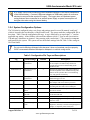
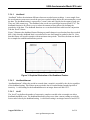
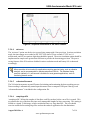
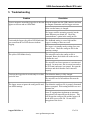
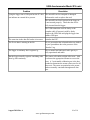
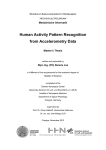
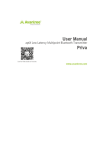
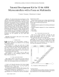
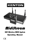
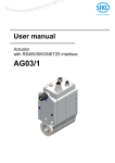
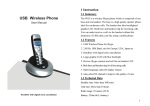
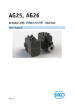
USB Accelerometer
Model X16-mini
1 Features
•
•
•
•
•
•
•
•
•
•
•
•
2 Applications
3-axis ±16g accelerometer
Operates from internal rechargeable
lithium-polymer battery
16-bit resolution
User selectable sample rate of 12, 25, 50,
100, 200, 400, 800 Hertz
Finite Impulse Response filter
Accurate time stamped data using Real
Time Clock (RTC)
Data recorded to a removable microSD
card (8GB included)
Easily readable comma separated text
data files
Data transfer compatible with Windows
or Linux via Universal Serial Bus (USB)
interface (no special software)
System appears as USB Mass Storage
Device to Windows and Linux OS’s.
LED indicator lights for system status
Compact size (2.0"L 1.0"W 0.5"H, 0.6oz)
(51mm 25 mm 13 mm, 17g)
The X16-mini is applicable to:
• Monitoring human motor activity, or
actigraphy, such as exercise intensity or
sleeping disorders.
• Wildlife studies
• Educational purposes
3 Description
The USB Accelerometer model X16-mini data
logger uses a low noise digital accelerometer
sensor, precise time stamped data logging,
microSD memory storage, real-time data access
and USB connectivity. Acceleration is collected
in X, Y, and Z axes and stored at a user
selectable rate of up to 800hz. When connected
via the USB to a personal computer, the X16mini appears as a standard mass storage device
containing the comma delimited data files and
user setup files. The 250mAh internal lithiumpolymer battery charges using the USB power
and provides approximately 24 hours of data
recording at 25 Hz.
Figure 1: X16-mini
August 2014 Rev A
1 of 16
www.gcdataconcepts.com
USB Accelerometer Model X16-mini
3.1 Operating Instructions
The X16-mini is a simple, economical solution to capture continuous motion data and quickly deliver
the information for analysis. The following instructions outline the steps to begin using the X16-mini.
Configuration settings and mounting methods will depend on the particular application.
Step 1: Ensure the internal Li-Poly battery is fully charged by plugging the X16mini into a computer USB port. Approximately 60 minutes will fully
charge a depleted 250mAh battery.
Step 2: Configure the X16-mini by editing the appropriate tags in the config.txt
file. Choose faster sample rates to capture fast acceleration events.
25Hz is sufficient for monitoring typical human and wildlife activity.
Refer to section 3.2.4 for configuration options.
Step 3: If necessary, initialize the RTC clock by creating a time.txt file (see
section 3.2.6).
Step 4: Unplug the X16-mini from the USB port and firmly attach the system to
the target object.
Step 5: To start the X16-mini, pass a magnet near the micro-B USB connector
where the magnetic switch is located. If the time.txt file is present, the
RTC is initialized with the time written in the file. The LED indicators
are visible through the semi-transparent enclosure. The red LED will
blink as the configuration file is accessed. Then, the yellow LED will
begin to blink at a 1 second interval indicating the system is operating.
The red LED will blink periodically as data is written to the microSD
card.
Step 6: Hold a magnet near the on/off switch for about 3 seconds to stop
recording. The LEDs will begin to blink rapidly for 2 seconds. Remove
the magnet and the X16-mini turns off.
Step 7: Connect the X16-mini to a computer USB port to access the data files.
The X16-mini requires a micro-B USB connector. Data is saved to a text
file located in the “GCDC” directory of the microSD card. The
accelerometer raw counts are converted to “g” by dividing the value by
2048.
August 2014 Rev A
2 of 16
www.gcdataconcepts.com
USB Accelerometer Model X16-mini
3.2 Electrical
The X16-mini is protected from general handling conditions by the plastic enclosure but is not
protected from adverse environmental conditions, such as rain, sweat, splashes, and water submersion.
The temperature range is limited primarily by the lithium-polymer battery capabilities.
Table 1: Operating Conditions
Parameter
Value
Temperature Range (Operating)
-5°F ~ 130°F (-20°C ~ 55°C)
Temperature Range (Storage)
-5°F ~ 80°F (-20°C ~ 25°C)
Relative Humidity (Operating and Storage)
<90%
3.2.1 Sensor
The X16-mini uses the Analog Devices ADXL345 3-axis digital accelerometer sensor. Table 2 lists
the basic sensor and logger performance parameters but refer to Analog Devices for detailed sensor
specifications. The sensor output is over-sampled and processed through a Finite Impulse Response
(FIR) filter. See section 3.2.5.1 for a detail description of the data format. Sensor orientation is
illustrated in Figure 2.
Table 2: Accelerometer Sensor Characteristics
Parameter
Acceleration range
Sensitivity
Sensitivity Deviation
Nonlinearity
Zero-g Offset Level
Accuracy
Condition
X, Y, Z axis
X, Y axis
Z axis
Min
Typical
Max
±16.0
2048
±1.0
±0.5
-150
-250
+150
+250
±0.1
Inter-Axis Alignment Error
±1
Cross-Axis Sensitivity
Units
g
count/g
%
%FS
mg
mg
Degrees
%
The accelerometer sensor is based on microelectromechanical systems (MEMS)
technology and is not affected by magnetic fields. Glue a magnet to the bottom of the
plastic enclosure to facilitate easy attachment to iron surfaces.
August 2014 Rev A
3 of 16
www.gcdataconcepts.com
USB Accelerometer Model X16-mini
+Y
+Z
+X
Figure 2: X16-mini Accelerometer Sensor Orientation
3.2.2 Indicator LEDs
System status is indicated by two LEDs located near the microB connector (see Figure 2). The yellow
LED blinks once per second indicating a properly operating system. The yellow LED blinks when the
X16-mini is recording data, in standby mode, or is connected to a computer via the USB port. The red
LED blinks when data is written or read from the microSD memory card. In data logging mode, the
period at which the red LED blinks depends on the sample rate and other configuration settings. The
yellow and red LEDs will flicker during a user initiated shutdown. The “statusindicators” tag in the
system configuration file turns off or changes the brightness of the LEDs (see section 3.2.4.10).
3.2.3 Battery
The X16-mini is powered by a internal, hardwired 250mAh lithium-polymer rechargeable battery. The
internal battery management system recharges the battery when the X16-mini is plugged into a USB
port or attached to a USB 5v power adapter. The battery provides approximately 24 hours of operation
sampling at 25 Hz with the deadband set to zero (maximum data recording capability). The battery is
not used when the system is connected to a computer USB port.
The data logger may draw up to 250mA from the USB supply to recharge the battery.
Plugging multiple data loggers into a USB hub can exceed the power capacity of the hub.
This can cause “brown-outs” of the logger and possibly damage the microSD card.
The logger is always “on” maintaining the real time clock and will eventually discharge the
battery completely after several months. The battery must be charged occasionally or
remove the battery disconnect jumper to completely deactivate the device for long-term
storage. Keep in a cool (20°C/ 68°F) dry environment to avoid damage of the battery.
August 2014 Rev A
4 of 16
www.gcdataconcepts.com
USB Accelerometer Model X16-mini
A 5v supply via the USB connector provides extended operation of the device independent
of the internal battery. Common USB power adapters or USB battery packs for consumer
electronics can provide the required 5v supply. The logger does not implement power
saving features when connected to an external power supply so power consumption will
be higher than when using the internal battery.
3.2.4 System Configuration Options
The X16-mini is configured using a set of tags and settings stored in a text file named “config.txt”,
which is located in the root directory of the microSD card. The system reads the configuration file at
boot time. Table 3 lists the configuration file tags. A tag is followed by an equal sign (“=”) and an
applicable tag setting. A line finishes with a newline character (0x0A). Tags are not case sensitive.
Tab and space characters are ignored. Lines starting with a semicolon (“;”) are treated as comments
and ignored by the system. The system will use the default settings listed in Table 3 if the config.txt
file is not found.
Do not use the Windows Notepad editor because it does not terminate new lines properly.
GCDC recommends Windows Wordpad or Notepad++ to edit the config.txt file.
Table 3: Configuration File Tags and Descriptions
Tag
Valid Settings
Default
Description
deadband
An integer between
0 and 32767
0
deadbandtimeout
An integer between
0 and 65535
3
dwell
1
microres
An integer between
0 and 65535
-
Off
rebootondisconnect
-
off on disconnect
samplesperfile
An integer greater
than 0
12, 25, 50, 100, 200,
400, 800
See section 3.2.4.8
-
28896
“Normal”, “High”,
“Off”
Normal
Sets the deadband to a range expressed in “counts”.
A new sample is recorded if any sensor axis
exceeds the previous recorded reading by the
deadband value
Specifies the period in seconds when a sample is
recorded regardless of the deadband setting. This
feature ensures periodic data is recorded during
very long periods of inactivity.
The number of samples recorded after a deadband
threshold triggered event
The presence of this tag sets the device to record
time stamps with 0.1ms effective precision.
The presence of this tag causes the system to start
recording after disconnect from a USB port.
The number of lines of data per data file before a
new file is created
Sets the rate at which data is collected and recorded
to the microSD card.
Defines when to start and stop recording
Stops data logging if 5v USB power is present (see
section 3.2.4.9)
LED status indicators can be activated with normal
brightness (Normal), activated with high brightness
(High), or completely deactivated (Off).
samplerate
starttime and stoptime
stoponvusb
statusindicators
25
Off
August 2014 Rev A
5 of 16
www.gcdataconcepts.com
USB Accelerometer Model X16-mini
3.2.4.1
deadband
“deadband” defines the minimum difference between recorded sensor readings. A new sample from
the accelerometer sensor must exceed the previous recorded reading before the microcontroller records
the data. The deadband setting is expressed in "counts" units and is applied to the output of each axis.
There are 2048 counts per g. The deadband value can be set to an integer between 0 and 32767. The
deadband function is an effective way to reduce the amount of data collected by defining the
granularity of the data. The deadband functions as a event threshold limit when used in conjunction
with the “dwell” feature.
Figure 3 illustrates the deadband feature filtering out small changes in acceleration from the recorded
data. Only when the deadband limit is exceeded will a new data sample be pushed to the file. Note
that this feature will result in samples with inconsistent time periods. Therefore, the data sets should
be re-sampled to establish uniform time periods.
Figure 3: Graphical Illustration of the Deadband Feature
3.2.4.2
deadbandtimeout
“deadbandtimeout” defines the period in seconds when a sample is recorded by the device regardless
of the deadband setting. This feature ensures periodic data is recorded during extended periods of
inactivity. A valid setting for the deadbandtimeout is an integer between 0 and 65535.
3.2.4.3
dwell
The “dwell” tag defines the number of consecutive samples recorded at the set sample rate after a
deadband threshold event. The deadband threshold event occurs when a sensor reading exceeds the
last recorded value by the deadband setting. A valid dwell setting is an integer between 0 and 65535.
August 2014 Rev A
6 of 16
www.gcdataconcepts.com
USB Accelerometer Model X16-mini
Figure 4: Graphical Illustration of the Dwell Feature
3.2.4.4
microres
The “microres” option sets the device to record time stamps with 0.1ms precision. In micro-resolution
mode, the time stamps are recorded as XX.YYYYZZ where XX are seconds, YYYY are 0.1
milliseconds, and ZZ are spurious digits that should be ignored. The micro-resolution option should be
implemented at sample rates greater than 200 hertz to provide the best timing precision. The power
saving features of the X16-mini are disabled in micro-resolution mode and battery life is shortened
accordingly.
Micro-resolution is best suited for applications requiring precise timing, such as vibration
analysis, and is recommended for sample rates above 200 Hz. The standard timing
precision (default) of 1 milli-second is suitable for most general applications, such as
monitoring human motion.
3.2.4.5
rebootondisconnect
The X16-mini incorporates an on/off button for initiating and terminating the data recording process.
Data recording is automatically started upon disconnect from a computer USB port if the tag word
“rebootondisconnect” is included in the configuration file.
3.2.4.6
samplesperfile
“samplesperfile” defines the number of data lines each file can have before a new file is created. This
tag controls the size of the data files into easily manageable lengths for later processing. This setting is
loaded as a signed 32-bit integer, which can translate into very large data files. The user should
exercise caution before setting large files and test the end-user application for data limitations.
August 2014 Rev A
7 of 16
www.gcdataconcepts.com
USB Accelerometer Model X16-mini
3.2.4.7
samplerate
The “samplerate” tag defines the data rate in Hertz, or samples per second. Valid sample rate settings
are 12, 25, 50, 100, 200, 400, and 800 Hz.
The X16-mini uses a digital MEMS type accelerometer sensor similar to those used in
cellphones, laptops, hard drives and other consumer electronics. The sensor streams data
at a selected rate based the on timing of a clock internal to the sensor. This sensor clock
isn't perfect and the precision and drift are undefined. For example, a selected sample rate
of 50 Hz may actually occur at 52 Hz. The X16-mini incorporates a precise real time clock
to independently time stamp the sensor data and ensure that accurate timing is recorded
to the data file. Therefore, always reference the time stamps to determine the actual
sample rate.
3.2.4.8
starttime and stoptime
The X16-mini starts and stops data recording based on the times defined using the “starttime” and
“stoptime” tags. The times must be in “MM HH DD” 24-hr format with the three entries separated by
a space. Entries marked with “*” operate as a wild card. The X16-mini continues to record after the
start time unless defined otherwise by the stoptime tag. Note that the configuration option does not
include the month. Example timing configurations:
Example 1: On the 15th day, start recording at 12:30pm and stop
recording at 6:00pm.
starttime = 30 12 15
stoptime = 00 18 15
Example 2: Start recording at the beginning of every hour and stop
recording 45 minutes later.
starttime = 00 *
stoptime = 45 *
3.2.4.9
stoponvusb
The “stoponvusb” tag stops data logging operations when a 5v supply is detected on the USB
connector. Add the “rebootondisconnect” option so the logger will resume recording when removed
from the 5v supply. This configuration is convenient for halting data logging while charging the
battery from a USB power supply. Without the stoponvusb option (default), the device switches power
from the internal battery to the USB 5v and continues to log data.
3.2.4.10 statusindicators
The brightness intensity of the LED status indicators is defined using the “statusindicators” tag and
valid settings of “normal”, “high”, and “off”.
August 2014 Rev A
8 of 16
www.gcdataconcepts.com
USB Accelerometer Model X16-mini
3.2.4.11 Example Configuration Files
Example A) The following configuration records data at 100 hertz. Deadband and deadbandtimeout
are set to zero so the logger will record constantly at the set sample rate. Each data file is 90,000 lines
long, which is 15 minutes of data. The status indicators are set to high brightness. The logger is
activated with the on/off button (rebootondisconnect is not active).
;Example X16-mini config file
;set sample rate
;available rates 12, 25, 50, 100, 200, 400, 800
samplerate = 100
;record constantly
deadband = 0
deadbandtimeout = 0
;set file size to 15 minutes of data
samplesperfile = 90000
;set status indicator brightness
statusindicators = high
;rebootOnDisconnect
;see X16-mini user manual for other config options
Figure 5: Configuration File Example A
Example B) The deadband and dwell settings configure the device to record at least 5 seconds of data
when a change greater than 0.1g is detected. The deadbandtimeout setting forces a sample write every
hour.
; Example X16-mini Config file
; set to 25Hz
samplerate = 25
; trigger at 0.1g
deadband = 100
; record 5 seconds of data
dwell = 125
;force a write every hour
deadbandtimeout = 3600
; set file length
samplesperfile = 30000
; LEDs on
statusindicators = normal
Figure 6: Configuration File Example B
Example C) The logger must be turned on with the on/off button. It will enter a standby mode (yellow
LED blinks) while it waits for the start time. The logger will start recording at 10:30am and turn off at
2:00pm. The logger will record constantly at 400Hz and create 51 data files in the 3.5 hours. The
micro-resolution is activated to provide the best timing precision at the 400 Hz sample rate.
August 2014 Rev A
9 of 16
www.gcdataconcepts.com
USB Accelerometer Model X16-mini
; Example X16-mini Config file
; set to 400Hz
samplerate = 400
; activate precision timing
microres
; record constantly
deadband = 0
deadbandtimeout = 0
; set file length
samplesperfile = 100000
; set logger to turn on with clock
starttime = 30 10
stoptime = 00 14
; LEDs on
statusindicators = normal
Figure 7: Configuration File Example C
3.2.5 Data Files
The X16-mini creates a new data file when the system is booted or when the maximum number of data
lines is reached in the previous data file. A system boot condition occurs when the logger is turned on,
or 5v power is restored to the system via the USB connector, or when the X16-mini is removed from a
computer USB port with the “rebootondisconnect” feature enabled. Data files are placed in a folder
named “GCDC” and are named data-XXX.csv, where XXX is a sequential number starting with 001.
The system will create up to 999 files. At the beginning of each file, a header is written describing the
system configuration and the current time when the file was created. Figure 8 represents an example
data file.
;Title, http://www.gcdataconcepts.com, X16-mini, Analog Dev ADXL345
;Version, 779, Build date, Jul 31 2014, SN:CCDC10161316547
;Start_time, 2014-08-14, 10:37:54.000
;Temperature, -999.0, deg C, Vbat, 3740, mv
;SampleRate, 50,Hz
;Deadband, 0, counts
;DeadbandTimeout, 5,sec
;Headers, time,Ax,Ay,Az
0.013,89,-572,1924
0.033,98,-590,1935
0.054,101,-588,1890
0.075,128,-567,1865
0.095,124,-584,1896
0.116,98,-597,1901
0.137,110,-588,1910
0.157,110,-592,1867
0.178,108,-608,1862
0.199,121,-588,1906
0.220,107,-554,1853
0.240,99,-565,1899
0.261,107,-561,1976
0.282,83,-556,1910
Figure 8: Example Data File
August 2014 Rev A
10 of 16
www.gcdataconcepts.com
USB Accelerometer Model X16-mini
3.2.5.1
Data Format
Data is written to files in comma separated text format starting with the file header information and
followed by event data entries. Table 4 lists the valid header tags, although not all tags may occur in
the header. Each data line contains a time entry and the raw accelerometer sensor readings from the X,
Y, and Z axes. The time entry is seconds elapsed from the start time recorded in the header. Add the
elapsed time to the start time to determine the complete date and time of the sample.
The last line of the final data file records the reason for the termination, such as “shutdown: switched
off”, “shutdown: low battery”, “shutdown: max files exceeded”, “shutdown: vbus disconnect”, or
“connected to computer”. The line is designated as a comment with a semicolon (“;”).
Table 4: Data File Header Tags
Tag
Description
Deadband
A new sample from the sensor must exceed the last reading by the deadband value
DeadbandTimeout
The period in seconds when a sample is recorded regardless of the deadband setting
Headers
The names of each column of data in the file
SampleRate
Rate at which data is recorded to the microSD card
Start_Time
The current time when the data file was created
Temperature
Disregard the temperature entry, the X16-mini does not collect temperature
Title
The name of the USB Accelerometer X16-mini unit and sensor type
Vbat
Battery voltage measured at the file start time
Version
The version control information of the firmware, including unique serial number
3.2.5.2
Data Conversion
The X16-mini records the raw digital data from the accelerometer sensor. This helps reduce processor
load, increase sample rate capability, and avoid data errors due to floating point calculations. The
X16-mini logger over-samples the sensor 4 times the selected sample rate requested in the config.txt
file. The over-sampled data is processed through a Finite Impulse Response filter (64 tap N4R4M2).
The resulting 16-bit data, or 65536 discreet counts, covers the full range of the +/-16g sensor.
Therefore, each discreet count equates to 32/65536=2048 counts/g.
Table 5 lists the converted data using the example data in Figure 8
August 2014 Rev A
11 of 16
www.gcdataconcepts.com
USB Accelerometer Model X16-mini
Table 5: Example Data Conversion
Raw Data (Low Gain)
Time
Ax
Converted Data
Ay
Az
Time
Ax (g)
Ay (g)
Az (g)
0.013
89
-572
1924
08/14/2014 10:37:54.010
0.0435
-0.2793
0.9395
0.033
98
-590
1935
08/14/2014 10:37:54.030
0.0479
-0.2881
0.9448
0.054
101
-588
1890
08/14/2014 10:37:54.051
0.0493
-0.2871
0.9229
0.075
128
-567
1865
08/14/2014 10:37:54.072
0.0625
-0.2769
0.9106
0.095
124
-584
1896
08/14/2014 10:37:54.092
0.0605
-0.2852
0.9258
0.116
98
-597
1901
08/14/2014 10:37:54.113
0.0479
-0.2915
0.9282
0.137
110
-588
1910
08/14/2014 10:37:54.134
0.0537
-0.2871
0.9326
0.157
110
-592
1867
08/14/2014 10:37:54.154
0.0537
-0.2891
0.9116
0.178
108
-608
1862
08/14/2014 10:37:54.175
0.0527
-0.2969
0.9092
0.199
121
-588
1906
08/14/2014 10:37:54.196
0.0591
-0.2871
0.9307
0.220
107
-554
1853
08/14/2014 10:37:54.217
0.0522
-0.2705
0.9048
0.240
99
-565
1899
08/14/2014 10:37:54.237
0.0483
-0.2759
0.9272
To determine acceleration in g's, divide the raw data by 2048. A “g” is 32.174 ft/sec^2 or
9.807 m/sec^2.
3.2.6 Real Time Clock
A real time clock (RTC) is integrated into the X16-mini and is used to determine time for each line of
data recorded. The RTC is set using a text file named “time.txt” located in the root directory of the
microSD card. The system looks for the time.txt file upon booting. If the file exists, the time stored in
the file is loaded to the RTC and the time.txt file is deleted. The time information in the time.txt file
must be in the exact “yyyy-MM-dd HH:mm:ss” 24-hour format, occur on the first line, and end with a
newline character. Figure 9 provides an example time.txt file that will initialize the RTC to 2:26:30
pm June 16, 2014.
The time file method of setting the RTC does not require special communication drivers so it can be
implemented using a simple text editor. Direct initialization of the RTC is possible but requires
specific device drivers and software from Gulf Coast Data Concepts.
August 2014 Rev A
12 of 16
www.gcdataconcepts.com
USB Accelerometer Model X16-mini
The RTC maintains ±5ppm accuracy (-40°C to +85°C), which means that it will drift accuracy about 1
second every 2 days. The RTC is powered by the battery at all times, even when the logger is “off”.
2014-06-16 14:26:30
Figure 9: Example Time Initialization File
Initializing the RTC ensures that the start time and individual time stamps can be
correlated to an absolute time – the year, month, day, hour, minute, second, and fractional
second. An uninitialized or reset of the RTC will lead to indeterminate time stamps.
After unplugging the logger from the USB port, the logger will load the time.txt file when it
is activated with the magnetic switch or if the “rebootondisconnect” option is active.
Therefore, there is a delay between when the time.txt was created and when the logger
actually loads the time information. For most applications, this simple method of initializing
the clock results in sufficient accuracy.
3.2.7 Memory Card
The X16-mini stores data to a removable 8GB microSD flash memory card and is compatible with
microSD and microSDHC type cards. The X16-mini functions as a Mass Storage Device to computer
operating systems when transferring data to and from the microSD memory card. The Mass Storage
Device interface is supported by all desktop operating systems and special device drivers are not
required. Tablet computers may not recognize the X16-mini due to USB device limitations set by the
tablet manufacturer.
The logger needs only the config.txt file to operate. The X16-mini will use default configuration
settings if the config.txt is not present. The “config.txt” and “time.txt” files must occur in the root
directory (see section 3.2.4 and section 3.2.6). The X16-mini will create a folder called “GCDC”, if
not already present, to place the data files (see section 3.2.5).
Interrupting the power to the logger can result in corruption of the microSD card. For
example, removing the logger from the USB port during file transfers to the PC. Reformat
the card if it becomes corrupted (FAT32 file structure). If data transfers to/from the card
become slow, consider formatting the card using “SD Card Formatter” software provided
by the SD Association (www.sdcard.org).
August 2014 Rev A
13 of 16
www.gcdataconcepts.com
USB Accelerometer Model X16-mini
3.3 Mechanical
The X16-mini is protected by a plastic enclosure measuring 2.00x1.00x0.50 inch (51x25x13mm) and
weighs 0.55oz (16 grams). The enclosure is not weatherproof and further protection is recommended
for outdoor use. A sealed plastic bag or adhesive lined heat shrink can protect the X16-mini from
moderate water exposure.
1.00 in
[25 mm]
2.00 in
[52 mm]
.50 in
13 mm
Figure 10: X16-mini
Gulf Coast Data Concepts, LLC
Name
Date
Project:
Drawn
Title:
REV
SIZE
0
A
The X16-mini is small and very light weight
so attachment methods do not need to be
UNLESS OTHERWISE SPECIFIED
NAME: X8M-3mini.dft
ARE IN INCHES glueFILE
substantial. Double-sided tape, a spot of DIMENSIONS
cyanoacrylate
(contact
cement), zip-ties,
SCALE:
SHEET 1 OF 1
magnetic base, or adhesive putty are example methods of attachment. These methods do
not cause adverse signal attenuation considering the relatively low frequency bandwidth
of the X16-mini logger. Command Poster Adhesive strips by 3M offer excellent temporary
attachment of the logger to most surfaces.
4 Software
The X16-mini records data to comma delimited text files and uses text based files for configuration
settings. Therefore, no special software is required to utilize the X16-mini. For data analysis, Gulf
Coast Data Concepts recommends using a commercial or open source mathematics package, such as
MatLab, Microsoft Excel, OpenOffice Calc, Octave, R, or similar applications.
August 2014 Rev A
14 of 16
www.gcdataconcepts.com
USB Accelerometer Model X16-mini
5 Troubleshooting
Problem
Resolution
I pass a magnetic around the logger but it does not Keep the magnet near the USB connector and turn
appear to activate and no LEDs blink.
the magnet orientation until the logger activates.
Make sure the battery is charged.
The logger could be operating correctly but the
status indicators are turned off. Check the
“statusindicator” option in the config.txt file.
I activated the logger, the yellow LED blinks once The deadband setting is set too high and the
per second but the red LED does not indicate
logger is waiting to detect an event.
logging.
The logger is in standby mode waiting for a start
time to occur. Check the config.txt file for the
start/stop settings.
The yellow LED blinks slowly.
The microSD card or the config.txt file is
corrupted. Run a check-disk test on the card or
reformat the card.
The microSD card is not present or is not inserted
properly. In most cases, this is not an issue unless
the X16-mini enclosure was opened. Re-open the
enclosure and check that the card is inserted
properly
I activate the logger but it records only for a short Check that the battery is fully charged.
period of time.
The microSD card is full and data files must be
deleted.
The logger seems to ignore the config.txt file and Check that the config.txt file is properly formatted
use default settings.
and not corrupted. Each setting should occur on a
separate line.
Some IT organizations implement an automatic
encryption of all removable media devices. This
will encrypt the config.txt file and the logger will
not be able to access the file. Do not allow
encryption of the device.
August 2014 Rev A
15 of 16
www.gcdataconcepts.com
USB Accelerometer Model X16-mini
Problem
Resolution
I plug the logger into a USB port but the PC does The microSD card is corrupted or damaged.
not indicate an external drive present.
Reformat the card or replace the card.
The microSD card is not present in the logger or
is not inserted properly. Check that the card is
fully inserted into the logger.
The USB connection could be faulty or the
extender cable (if present) could be faulty.
Replace the USB cable and plug the logger into
another USB port.
The start time in the data file header is incorrect.
Initialize the RTC.
The Z-axis data is missing in the file.
No, it's present but the column headers are shifted
in your spreadsheet due to the presence of the
“headers” tag.
The logger is stationary but it registers 1g.
This is normal and indicates Earth's gravity is
fully operational and stable.
But the logger actually registers something other
than 1g when stationary.
The sensor will exhibit a slight offset error. Add
or subtract the appropriate amount to correct the
error. A 3-axis tumble calibration test is the best
method to determine the sensor offset error for all
three axis. The errors are particular to the sensor
and are normally consistent throughout all data
sets.
August 2014 Rev A
16 of 16
www.gcdataconcepts.com