1
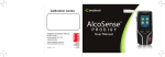
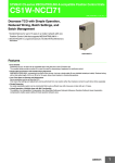
3FLEX™ SPC-7100
Stereo Platform Controller
User Manual
v0.0.1 – December 5th, 2011
COPYRIGHT © 2011 3ALITY DIGITAL LLC. ALL RIGHTS RESERVED.
3FLEX™ SPC-7100
v0.0.1 – December 5th, 2011
1
Authors
MaBe – Martin Beck
Revision History
Revision
0.0.1
Date
Dec 5rd, 2011
Authors
MaBe
Changes
Initial Draft: basic documentation for cert purposes.
Derived from SPC7000-UserManual_0.0.1.doc
Intended Readers
Users, Operators, System-Integrators
Subject
How to use the SPC-7100
Document Version/Date
v0.0.1 – December 5th, 2011
Applicable for Device Version
All devices
Filename
SPC7100-UserManual_0.0.1.doc
2
3FLEX™ SPC-7100
v0.0.1 – December 5th, 2011
Preface
This document contains instruction and reference information for the operation and use of the
3FLEX™ SPC-7100 Stereo Platform Controller
Trademarks
3FLEX, 3PLAY, 3ACTION and 3SPACE are trademarks of 3ality Digital LLC. All other brand and product
names mentioned herein are used for information purposes only and may be trademarks or registered
trademarks of their respective companies.
3FLEX™ SPC-7100 Stereo Platform Controller User Manual
Copyright © 2011 3ality Digital Systems LLC. All rights reserved.
Reproduction, adaptation or translation of this document without prior permission is prohibited, except as
allowed under copyright laws.
Note: The information in this document is subject to change without notice or obligation.
Technical Support
Telephone:
+1 (818) 333-3010
Fax:
+1 (818) 333-3001
Email:
[email protected]
Web:
www. 3alitytechnica.com/support
Address:
Customer Service
3ality Digital Systems LLC.
55 E. Orange Grove Ave
Burbank, CA 91502
United States of America
Hours: 9:00am to 6:00pm Pacific Time • Monday through Friday
3FLEX™ SPC-7100
v0.0.1 – December 5th, 2011
3
United States of America (USA)
Federal Communications Commission (FCC) Notice
This equipment has been tested and found to comply with the limits for a Class A
digital device, pursuant to Part 15 of the FCC Class rules. These limits are designed to
provide reasonable protection against harmful interference when the equipment is
operated in a commercial environment. This equipment generates, uses, and can
radiate radio frequency energy and, if not installed and used in accordance with the
instruction manual, may cause harmful interference to radio communications.
Operation of this equipment in a residential area is likely to cause harmful interference
which the user will be required to correct at his expense. To assure continued
compliance follow the attached installation instructions and do not make any
unauthorized modifications.
European Commission (EC)
Waste Electrical and Electronics Equipment (WEEE) Directive
Do not dispose of this device. At the end of its life-cycle, this device must be properly
recycled by a specialized recycling firm or returned to the manufacturer or vendor for
proper disposal.
Finland
Laite on liitettävä suojamaadoituskoskettimilla varustettuun pistorasiaan.
Norway
Apparatet må tilkoples jordet stikkontakt.
Sweden
Apparaten skall anslutas till jordat uttag.
WARNING:
TO REDUCE THE RISK OF FIRE OR SHOCK HAZARD, DO NOT EXPOSE THIS EQUIPMENT TO RAIN OR
MOISTURE.
CAUTION:
TO REDUCE THE RISK OF FIRE OR SHOCK HAZARD AND ANNOYING INTERFERENCE, USE THE
RECOMMENDED ACCESSORIES ONLY.
4
3FLEX™ SPC-7100
v0.0.1 – December 5th, 2011
Table of Contents
Page
1
Official Notices ......................................................................................................6
1.1
1.2
1.3
1.4
1.5
2
Introduction ..........................................................................................................8
2.1
2.2
2.3
2.4
2.5
2.6
2.7
3
Remote Device Configuration ................................................................................................ 14
Firmware Upgrade ................................................................................................................ 14
Specifications ......................................................................................................15
5.1
5.2
6
General Safety...................................................................................................................... 13
Specific Safety...................................................................................................................... 13
Additional Notes ................................................................................................................... 13
Device Configuration ...........................................................................................14
4.1
4.2
5
Purpose and Scope of this Manual ...........................................................................................8
Description.............................................................................................................................8
Overview................................................................................................................................8
Main Tasks of the 3FLEX™ SPC-7100 .......................................................................................8
Main Aspects and Overview .....................................................................................................9
3FLEX™ ControlChain ........................................................................................................... 11
3FLEX-SPC 7100 Internal Power Schematics........................................................................... 12
Before you start...................................................................................................13
3.1
3.2
3.3
4
Limitation of Liability...............................................................................................................6
Software License Agreement ...................................................................................................6
3ality Digital Hardware Warranty .............................................................................................6
3ality Digital Software Warranty ..............................................................................................7
Obtaining Warranty Service and Customer Support...................................................................7
Physical................................................................................................................................ 15
Connectors and Interfaces .................................................................................................... 16
Appendix .............................................................................................................18
6.1
6.2
6.3
Declarations of Conformity .................................................................................................... 18
SPC7100 Cabling .................................................................................................................. 19
Table of Figures.................................................................................................................... 21
3FLEX™ SPC-7100
v0.0.1 – December 5th, 2011
5
1 Official Notices
1.1
Limitation of Liability
3ality Digital LLC shall not be liable for indirect, special, incidental or consequential damages; for
damages that directly or indirectly arise from the use of, or inability to use, the system; for commercial
loss of any kind; for the procurement of substitute goods – whether arising in tort, contract or any other
legal theory, even if 3ality Digital LLC has been advised of the possibility of such damages. In any event,
3ality Digital LLC’s liability shall be limited to the amount actually paid for the system giving rise to any
such damage. This limitation is intended to limit 3ality Digital LLC’s liability and shall notwithstanding any
failure of essential purpose of any limited remedy.
1.2
Software License Agreement
IMPORTANT – READ CAREFULLY: This Software License Agreement is a legal agreement between
3ality Digital’s Customer and 3ality Digital LLC. This system contains certain 3ality Digital software,
hardware, associated media, printed materials and electronic documentation. By using the system
described in this manual, the customer agrees to be bound by the terms of this Software License
Agreement. If the customer does not agree to the terms of this Software License Agreement, 3ality
Digital LLC is unwilling to license the software to the customer. In such case, the customer may not use
or copy the software.
License: 3ality Digital LLC grants an exclusive, nontransferable, limited license to use the installed
software exclusively on hardware on which 3ality Digital has installed the software, or on hardware on
which 3ality Digital has authorized it to be installed, for the period of time that the software is licensed.
Such software may only be enabled, activated, modified or updated by 3ality Digital or its authorized
agent. 3ality Digital and its licensors retain the right, title and interest in and to all software. Title to the
media on which the software is delivered is transferred to the Customer.
Restrictions: The software is copyrighted and may contain material that is protected by patent, trade
secret or other laws pertaining to proprietary rights. No copies of the software may be made, except for a
single copy for archival purposes. You may not modify the Software or permit or assist any third party in
doing so. You may not decompile, reverse engineer, disassemble, or otherwise reduce the Software to
source code or other human-readable form, or attempt or permit any third party to do so. Any violation
of this Software license shall be a material breach and shall immediately entitle 3ality Digital LLC to
exercise any remedy that may exist at law or in equity.
Copyright: All title and copyrights in the Software (and any copies thereof) and the accompanying
printed materials are owned by 3ality Digital LLC. All rights not specifically granted under this Software
License Agreement are reserved by 3ality Digital LLC.
1.3
3ality Digital Hardware Warranty
(a) Company warrants to the original purchaser of Equipment that for the Warranty Period (as defined
below), the Equipment will be free from material defects in materials and workmanship. The foregoing
warranty is subject to the proper installation, operation and maintenance of the Equipment in accordance
with installation instructions and the operating manual supplied to Customer. Warranty claims must be
made by Customer in writing within sixty (60) days of the manifestation of a problem. Company's sole
obligation under the foregoing warranty is, at Company's option, to repair, replace or correct any such
defect that was present at the time of delivery, or to remove the Equipment and to refund the purchase
price to Customer.
(b) The "Warranty Period" begins on the date the Equipment is delivered and continues for 12 months.
(c) Any repairs under this warranty must be conducted by an authorized Company service representative
at an authorized repair facility. The customer is responsible for costs associated with shipping the
equipment to and from an authorized repair facility.
(d) This warranty is for the hardware and hardware sub-systems of the equipment and specifically
excluded from the warranty is all software, (which is covered under the software warranty), problems
due to accidents, misuse, misapplication, storage damage, negligence, or modification to the Equipment
or its components.
6
3FLEX™ SPC-7100
v0.0.1 – December 5th, 2011
(e) Company does not authorize any person or party to assume or create for it any other obligation or
liability in connection with the Equipment except as set forth herein.
(f) The warranty in section (a) above is exclusive and in lieu of all other indemnities or warranties,
whether express or implied, including the implied warranties of merchantability and fitness for a
particular purpose.
Limitation of Liability. In no event shall company be liable for any indirect incidental, punitive, special or
consequential damages, or damages for loss of profits, revenue, or use incurred by customer or any third
party, whether in an action in contract, or tort, or otherwise even if advised of the possibility of such
damages. Company’s liability for damages arising out of or in connection with this agreement shall in no
event exceed the purchase price of the defective equipment. The provisions of this agreement allocate
risks between company and customer. Company’s pricing reflects this allocation of risk and but for this
allocation and limitation of liability, company would not have entered into this agreement.
1.4
3ality Digital Software Warranty
3ality Digital represents and warrants that the Software shall perform substantially as represented in the
Documentation.
WARRANTY LIMITATION: THE FOREGOING WARRANTY IS IN LIEU OF ALL OTHER WARRANTIES,
EXPRESSED OR IMPLIED, INCLUDING BUT NOT LIMITED TO, IMPLIED WARRANTIES OF FITNESS FOR A
PARTICULAR PURPOSE AND WARRANTIES OF MERCHANTABILITY. EXCEPT FOR THE WARRANTY
EXPRESSLY ACKNOWLEDGED HEREUNDER, 3ALITY DIGITAL HEREBY DISCLAIMS AND CUSTOMER
HEREBY WAIVES ALL WARRANTIES, EXPRESS OR IMPLIED, INCLUDING BUT NOT LIMITED TO ALL
IMPLIED WARRANTIES OF FITNESS FOR A PARTICULAR PURPOSE AND IMPLIED WARRANTIES OF
MERCHANTABILITY.
Limitation of Damages: 3ality Digital shall not be liable to Customer under the Warranty for any
consequential, exemplary, incidental or punitive damages, regardless of whether 3ality Digital has been
advised of the possibility of such damages in advance or whether such damages are reasonably
foreseeable.
Force Majeure: 3ality Digital shall not be liable to Customer for failing to perform its obligations under the
Agreement because of circumstances beyond the control of Customer. Such circumstances shall include,
but not be limited to, any acts or omissions of any government or governmental authority, natural
disaster, act of a public enemy, riot, sabotage, dispute or differences with workmen, power failure, delays
in transportation or deliveries of supplies or materials, acts of God, terrorism, or any events reasonably
beyond the control of Customer.
Indemnification: Customer shall release, defend, indemnify and hold harmless 3ality Digital from and
against any claims, damages and liability arising from use of the Software or Documentation by Customer.
1.5
Obtaining Warranty Service and Customer
Support
The following information describes our current warranty support procedures. These procedures are
subject to change without notice and are expressly excluded from the Limited Warranty.
•
Our Customer Support Representatives are available to provide telephone support during
business hours (M-F, 9am-6pm Pacific Time), and after these hours for urgent “emergency”
technical support.
•
Customer Support will be provided only for products under warranty or those covered under a
valid Support Agreement.
•
Before returning the Product for repair, it is necessary to obtain a Return Merchandise
Authorization (RMA) number by calling (818) 333-3000. You will be asked to provide the system’s
serial number.
•
The non-functioning part should be properly packed and shipped pre-paid to 3ality Digital with
the RMA number clearly displayed on the outside of the package and on the accompanying RMA
form. We will refuse to accept any package without a valid RMA number.
•
Repairs outside the scope of the Limited Warranty require a valid and valid Support Agreement
prior to any repairs. 3ality Digital does not offer time and materials based repair services.
3FLEX™ SPC-7100
v0.0.1 – December 5th, 2011
7
2 Introduction
2.1
Purpose and Scope of this Manual
This manual describes mainly the physical aspects, hardware and the connectors of the 3FLEX™
SPC-7100 and its specific features. The software aspects and menu structure are currently not deeply
covered and will be subject of a different document.
2.2
Description
The 3FLEX™ SPC-7000 is a small device intended for indoor use and installation on a 3FLEX Stereo
Camera Platform, on a grip equipment or on a tabletop. It can be powered through the 3Flex
ControlChain, preferably through the Stereo Camera Platform (Rig), or alternatively through a suitable
3FLEX SIP Stereo Image Processor or a separate power-supply.
2.3
Overview
The 3FLEX™ SPC-7100 is a controlling device for 3alityTechnica’s range of Stereo Camera Platforms and
interface-box for a vast variety of digital peripheral devices, digital hand-controllers (demands) for Lensrelated parameters, such as Focus (F), Iris (I) and Zoom (Z), as well as 3D-related degrees of freedom,
such as Convergence (Cv) and Interaxial (IA) distances. Beyond these main tasks, the SPC-7100
seamlessly integrates with 3FLEX™ Stereo Image Processors (SIP’s) and other 3FLEX™ and 3SPACE™
products.
2.4
Main Tasks of the 3FLEX™ SPC-7100
The 3FLEX™ SPC-7100 Stereo Platform Controller is the successor of the very popular 3FLEX™ SPC-5000
and closely related to the 3FLEX™ SPC-7000 Stereo Platform Controller. Compared to the SPC-7000, the
SPC-7100 dos not have any analog interfaces and no local user-interface, with the significant benefit of a
drastically reduced form-factor. The main tasks of the SPC-7100 include:
8
•
Communication-Link in the 3Flex-ControlChain
•
Input: Non-metrical FIZAC reference values (from handcontrollers or SIPs)
•
Calculating the triangulations for up to 4 x 3D-motors
Convergence, Baseline -> FrontrailL, FrontrailR, BackrailL, BackrailR
•
Paired control of the 6 lens motors
FocusL, FocusR, IrisL, IrisR , ZoomL, ZoomR
•
Compensation of geometric errors (lenses, rig)
FrontrailL, FrontrailR, BackrailL, BackrailR , Height/Pitch-FrontrailR, H/P-BackrailR
•
Generation of metrical metadata (FIZAC)
•
Handling of calibration data for the rig and lenses
3FLEX™ SPC-7100
v0.0.1 – December 5th, 2011
2.5
Main Aspects and Overview
Figure 1.
3Flex SPC-7100: Top View
The most prominent side of the 3FLEX-SPC7100 is the top. Here, the SPC carries all labels for the
connectors, which are located on both the left and right side of the unit, as depicted in the following
photos:
Figure 2.
3Flex SPC-7100: Left and Right Side View
Most of the connectors are color-coded the speed-up reliable installation. Detailed connector description
is provided in the specification-section of this document. However, we strongly recommend the following
guidelines:
1. To avoid EMI/RFI issues, please use shielded cables only.
2. We highly recommend only usage of cables, which were purchased or certified through 3ality.
This guarantees a maximum of ease-of-use, compatibility, shielding, signal-integrity, as well as
proper color-coding and labeling.
3. Always make sure that the connector-type and pin-count and color-code of the plug on the cable
matches those of the receptacle on the SPC, that you are intending to plug the cable into. Failing
to do so will very likely mechanically damage the connectors, and electrically damage the devices
that you want to interconnect.
3FLEX™ SPC-7100
v0.0.1 – December 5th, 2011
9
2.5.1
Status-LED’s
Next to the LEMO connectors on the left side of the SPC-7100, Status-LED’s have been placed.
There is one bi-color LED located next to the 10pin LEMO connector with blue color-code, labeled “COM
OUT”. The meaning of this LED is as follows:
RED =
YELLOW =
GREEN =
OFF =
3FLEX ControlChain in rig direction: Receive Data Error
3FLEX ControlChain in rig direction: Legacy Mode
3FLEX ControlChain in rig direction: Valid Data Received
3FLEX ControlChain in rig direction: No Receive Data
Next to each of the 8pin LEMO connectors with black color-coding, labeled “Digital 1” and ”Digital 2”, red
LED’s have been located. The meaning of these LED’s is as follows:
OFF =
SOLID RED =
FLICKERING RED =
10
Port Inactive (not used)
Port Comm Error
Port Communicating
3FLEX™ SPC-7100
v0.0.1 – December 5th, 2011
2.6
3FLEX™ ControlChain
The current topology of the SIP/SPC/Rig-control is a daisy-chain, called 3FLEX-ControlChain:
SIP --- SPC[n] --- ... --- SPC[0] --- MRCU (RIG)
In this chain there can be one SIP and one Stereo Camera Platform (Rig), and multiple link-devices
between SIP and Rig. These links are typically 1 or 2 SPC´s (SPC-7000 and/or SPC-7100), but also other
devices such as the 3FLEX-3WM7000 or 3FLEX-SNU7800 are thinkable.
The transmission parameters for the entire chain are 115.2 kbps, n, 8, 1. In rare cases, with legacy
firmware running on the MRCU in the rig, the transmission parameters for the last link of the chain between SPC[0] and MRCU - are 125 kbps, n, 9, 1.
The communication between SIP and closest SPC can be either RS422 or RS232.
The communication between all other SPC’s and the Rig is RS422.
RS232 cabling should not exceed a length of about 5..10 meters.
3ality has tested RS422 communications with lengths up to 50m but this is clearly not the maximum.
However, the longer the cables get, the more important it is to use the right cable (Twisted pair,
impedance about 100...120 Ohms) and the right conductors twisted. You should make sure that the
following pin-pairs are twisted, if the length exceeds about 25 m: 3+4, 5+6, 8+9, 1+7. The cable should
be shielded and the shield should be connected to the LEMO connectors shell.
Also, it is important to know, that Power for the SPC’s is usually fed through the 3FLEX ControlChain
cables. It must be ensured that the voltage-drop on pins 1, 2, 9, 10 is not excessive.
Power
3FLEX
SIP
Stereo
Image
Processor
Camera L
Raw HD-SDI Video
SPC #n
3FLEX SPC7100
Stereo Platform
Controller
SPC #0
3FLEX SPC7100
Stereo Platform
Controller
HandController
(Demand)
HandController
(Demand)
Camera R
3FLEX TS-x
Stereo Camera
Platform
Video
Power
Motion-Control/Metadata + Power (3FLEX ControlChain)
Vendor-specific Control Data + Power
XXX 3ality Digital Systems
XXX Third Party Products
Figure 3.
3FLEX™ SPC-7100
v0.0.1 – December 5th, 2011
Typical In-System Configuration
11
2.7
3FLEX-SPC 7100 Internal Power Schematics
COM IN
REMOTE / SIP
COM OUT
LOCAL / RIG
DIGITAL 1
FIZ
Internal
SPC7100 Electronics
POWER IN
10…16VDC
DIGITAL 2
FIZ
3FLEX SPC7100
Figure 4.
3FLEX SPC7100 Internal Power Schematics
Normally, the SPC is powered by the Stereo Camera Platform (rig) through the COM OUT connector.
Power can be passed trough to other SPC´s in the 3FLEX ControlChain through the COM IN connector.
However, power can be supplied from either of the LEMO10 connectors, that means that the SPC can be
also powered through the COM IN connector. A high-performance schottky-diode has been added
internally to the design of the SPC7100, as depicted above, to prevent current flowing back to the rig.
This means, that if an SPC is powered through the COM IN connector, it cannot pass power to consumers
on the 3FLEX ControlChain, which are on the COM OUT side of the SPC.
If the SPC7100 is neither powered through the rig, nor through the SIP, it can be powered through the
receptacle, that mates with a 2,1mm Switchcraft barrel-connector and is labeled “POWER IN”. The SPC7100 comes with a universal Power-supply for this purpose; 3ality highly recommends you to use only
this provided power-supply.
12
3FLEX™ SPC-7100
v0.0.1 – December 5th, 2011
3 Before you start
3.1
General Safety
1. Operating may be done by qualified and trained personnel only.
2. Read these instructions.
3. Keep these instructions.
4. Heed all warnings.
5. Follow all instructions.
6. Do not use this apparatus near water.
7. Clean only with dry cloth.
8. Do not install near any heat sources such as radiators, heat registers, stoves, or other apparatus
(including amplifiers) that produce heat.
9. Do not operate outdoors in direct sunlight or in moist or rainy weather. Use appropriate covers in
case of moist or wet weather-conditions!
10. Do not defeat the safety purpose of the polarized plug. If the provided plug does not fit into your
outlet, consult an electrician for replacement of the obsolete outlet.
11. Protect all cables from being walked on or pinched.
12. Do not block venting holes.
13. Use only in ventilated and dry environment.
14. Only use attachments/accessories specified by the manufacturer.
15. Unplug this apparatus during lightning storms or when unused for long periods of time.
16. Refer all servicing to qualified service personnel. Servicing is required when the apparatus has
been damaged in any way, such as power-supply, its cord or its plug is damaged, liquid has been
spilled or objects have fallen into the apparatus, the apparatus has been exposed to rain or
moisture, does not operate normally, or has been dropped.
3.2
Specific Safety
CAUTION: Please make sure that nobody, neither you, nor a
colleague, nor a spectator, is touching the Stereo Camera Platform
(Rig) which is attached to the SPC, while you are operating or
configuring the SPC or attached hand-controllers. The Stereo Camera
Platform might move rapidly during operation through the SPC,
which might be harmful. Always beware of pinch-points on the
Stereo Camera Platform, especially when the SPC is directly mounted
onto the Stereo Camera platform!
3.3
Additional Notes
1. To avoid EMI/RFI issues, please use shielded cables only.
2. We highly recommend only usage of cables, which were purchased or certified through 3ality.
This guarantees a maximum of ease-of-use, compatibility, shielding, signal-integrity, as well as
proper color-coding and labeling.
3. Always make sure that the connector-type and pin-count and color-code of the plug on the cable
matches those of the receptacle on the SPC, that you are intending to plug the cable into. Failing
to do so will very likely mechanically damage the connectors, and electrically damage the devices
that you want to interconnect.
3FLEX™ SPC-7100
v0.0.1 – December 5th, 2011
13
4 Device Configuration
4.1
Remote Device Configuration
Unlike with the SPC-7000, the only method of configuring the SPC-7000 is remotely, through the
3FLEX ControlCenter Software. This powerful software is used to configure the entire range of 3FLEX
products and is subject of separate documents.
4.2
Firmware Upgrade
The SPC-7100 is designed and built around two powerful microprocessors. The firmware is constantly
improved and the SPC-7100 can be upgraded in-field through the 3FLEX-ControlChain. Please contact
3ality’s support for advice whether a firmware-upgrade might make sense for you and how to obtain it.
Your 3ality support-team will provide you with the 3FLEX FirmwareManager and with upgrade
instructions on demand.
14
3FLEX™ SPC-7100
v0.0.1 – December 5th, 2011
5 Specifications
5.1
Physical
Approximate
Dimensions
Weight
Operating Height
L = 92 mm or 3,7”
W = 70 mm or 2,8”
H = 30 mm or 1,2”
210 grams, or 7,5 oz
0...2000m (0…6500ft) above sea level
Operating Conditions
Temperature 0 °C to 45 °C or 32 to 113°F
Rel. Humidity 20% … 80% (non condensing)
Storage Conditions
Temperature -10 °C to 55 °C or 15 to 131°F
Rel. Humidity 0% … 80% (non condensing)
Power-supply
12V DC • 1Amax
Tolerance of
Power-Supply
10…16V DC
Ingress protection
RoHS compliance
3FLEX™ SPC-7100
v0.0.1 – December 5th, 2011
IP20. Designed for indoor usage only! If used outdoors, use appropriate
protection measures to prevent exposure of the device to moisture and rain!
YES
15
5.2
Connectors and Interfaces
5.2.1
Left 1: 3Flex ControlChain: COM OUT, Local/Rig
10 PIN Lemo, size 1B, Blue Color-Coding
(top left)
Use to connect ro Rig, or a loop-through to additional SPC-7100
Pin:
1
2
3
4
5
6
7
8
9
10
Function:
+12V Raw to SPC from Rig, fused at 1.35A
Ground Common to/from SPC
RS-422 RA+ to SPC from Rig
RS-422 RB- to SPC from Rig
RS-422 TA+ from SPC to Rig
RS-422 TB- from SPC to Rig
unused
unused
+12V Raw to SPC from Rig, fused at 1.35A
Ground Common to/from SPC
5.2.2
Female Receptacle - View on SPC
Left 2/3, DIGITAL-1/-2, F I Z
8 PIN Lemo, size 1B, Black Color-Coding
(2nd and 3rd from top left)
Use to connect a Preston PPA(HU3), or Preston HU2(FIZ2), or Canon or Fujinon Digital Focus/Zoom
Demand
Pin:
1
3
4
5
6
7
8
Function:
+12V Raw from SPC, fused at 900mA (if required to power external device)
RS-232 RxD to SPC
RS-232 TxD from SPC
RS-422 TB- from SPC
RS-422 TA+ from SPC
RS-422 RB- to SPC
RS-422 RA+ to SPC
Female Receptacle - View on SPC
16
3FLEX™ SPC-7100
v0.0.1 – December 5th, 2011
5.2.3
Right 1: 3Flex ControlChain: COM IN, Remote/SIP
10 PIN Lemo, size 1B, Blue Color-Coding
(top right)
Use to connect a SIP or a loop-through to additional SPC-7100
Pin:
1
2
3
4
5
6
7
8
9
10
Function:
+12V Raw from SPC, fused at 900mA
Ground Common to/from SPC
RS-422 TA+ from SPC
RS-422 TB- from SPC
RS-422 RA+ to SPC
RS-422 RB- to SPC
RS-232 TxD from SPC (to SIP)
RS-232 RxD to SPC (from SIP)
+12V Raw from SPC, fused at 900mA
Ground Common to/from SPC
5.2.4
Right 2: Power In
External Power Input 12 (10…16) VDC, 1Amp max.
(2nd from top right)
Switchcraft 722A barrel-receptacle
Mating plug: Switchcraft S761K barrel connector with lockring-nut.
Barrel diameter: 5.5mm / 0.38”; Inner diameter: 2.1mm / 0.08”
Pin:
1
2
Female Receptacle - View on SPC
+
-
Function:
External Power Input 12 (10…16) VDC, 1Amp max.
Ground Common
3FLEX™ SPC-7100
v0.0.1 – December 5th, 2011
17
6 Appendix
6.1
6.1.1
Declarations of Conformity
CE
Figure 5.
18
CE Declaration of Conformity
3FLEX™ SPC-7100
v0.0.1 – December 5th, 2011
6.2
SPC7100 Cabling
6.2.1
Cabling Overview
To Rig or next SPC(LEMO.1B.10)
720 004
To TECHNICA Rig (LEMO.1B.10)
720
720
720
720
002
003
006
007
720 025
COM OUT
COM IN
LOCAL / RIG
Preston HU3/PPA (LEMO.1B.8)
720 012
CANON Digital Demand (Bendix18)
CANON Digital Demand (HRS10-12)
CANON Digital Demand (HRS25-20)
CANON Digital Lens Motor Pack (HRS25-20)
720 013
720 014
720 015
720 017
FUJINON Digital Demand (HRS10-12)
FUJINON Digital Demand (Bendix10)
FUJINON Digital Lens Motor Pack (HRS25-20)
720 018
720 019
720 020
TECHNICA THC Digital Demand (LEMO.0B.6)
TECHNICA THC Digital Demand (LEMO.0B.6)
720 021
720 022
Figure 6.
COM OUT
DIGITAL 1
FIZ
3FLEX – S P C 7100
DIGITAL 2
FIZ
STEREO PLATFORM CONTROLLER
SPC Left Side Cabling Options
COM IN
LOCAL / RIG
REMOTE / SIP
REMOTE / SIP
720 002
720 003
720 006
720 007
720 004
From SIP or previous SPC (LEMO10)
DIGITAL 1
FIZ
DIGITAL 2
FIZ
3FLEX – S P C 7100
STEREO PLATFORM CONTROLLER
Figure 7.
3FLEX™ SPC-7100
v0.0.1 – December 5th, 2011
SPC Right Side Cabling Options
19
6.2.2
3ality Cables
PartNo Description
Comment
720 002 40cm Lemo10/blue 3Flex-ControlChain Systemcable
2x Lemo10-1B plugs, straight, blue, 40cm
720 003 10m Lemo10/ blue 3Flex-ControlChain Systemcable
2x Lemo10-1B plugs, straight, blue, 1000cm
720 004
40cm Cable-Coupler Lemo10/Lemo10/blue. Optional to link two
3FlxControlChain cables
2x Lemo10-1B jacks, straight, blue, 40cm
720 006 50m Lemo10/ blue 3Flex-ControlChain Systemcable
2x Lemo10-1B plugs, straight, blue, 5000cm
720 007 1,0m Lemo10/ blue 3Flex-ControlChain Systemcable
2x Lemo10-1B plugs, straight, blue, 100cm
720 012 SPC7000-PrestonHU3/PPA cable: 2xLemo8, black, 70cm
2x Lemo8-1B, straight, black, 70cm
720 013
SPC7000-CanonDigitalDemand(Bendix) cable: Bendix14/18-Lemo8, black,
RS422
150cm
720 014
SPC7000-CanonDigitalDemand(Hirose10-12) cable: Hirose10-12-Lemo8,
black, 150cm
RS422
720 015
SPC7000-CanonDigitalDemand(Hirose25-20) cable: Hirose25-20-Lemo8,
black, 40cm
RS422
720 017
SPC7000-CanonDigitalLensPack(Hirose25-20) cable: Hirose25-20-Lemo8,
RS422
black, 70cm
720 018
SPC7000-FujinonDigitalDemand(Hirose10-12) cable: Hirose10-12-Lemo8,
RS485; L2A Protocol
black, 40cm
720 019
SPC7000-FujinonDigitalDemand(Bendix12/10) cable: Hirose10-12-Lemo8,
RS485; L2A Protocol
black, 40cm
720 020
SPC7000-FujinonDigitalLensPack(Hirose25-20) cable: Hirose25-20-Lemo8,
RS232; L10 Protocol
black, 70cm
720 021 SPC7000-ET Handcontroller, Lemo0B.6p, Lemo1B.8p, 300cm/10ft
RS232
720 022 SPC7000-ET Handcontroller, Lemo0B.6p, Lemo1B.8p, 1500cm/50ft
RS232
720 025
20
SPC7000 (Lemo.1B.10 Blue) <-> Technica ControlBox (Lemo.1B.10
Orange), 0.6m
RS422, Power
3FLEX™ SPC-7100
v0.0.1 – December 5th, 2011
6.3
Figure
Figure
Figure
Figure
Figure
Figure
Figure
Table of Figures
1.
2.
3.
4.
5.
6.
7.
3Flex SPC-7100: Top View ..............................................................................................9
3Flex SPC-7100: Left and Right Side View ........................................................................9
Typical In-System Configuration .................................................................................... 11
3FLEX SPC7100 Internal Power Schematics .................................................................... 12
CE Declaration of Conformity......................................................................................... 18
SPC Left Side Cabling Options ....................................................................................... 19
SPC Right Side Cabling Options ..................................................................................... 19
3FLEX™ SPC-7100
v0.0.1 – December 5th, 2011
21