1
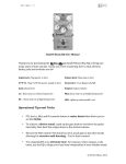
SHOEBOX ELECTRONIX
8385V ECU MONITOR
USER MANUAL
&
TROUBLESHOOTING GUIDE
Sept 28, 2008
10/5/2008
1
Table of Contents
Your Vanagon & it’s ECU................................................................................................. 3
Vanagon ECU & System Components.............................................................................. 4
ECU Input Signals ............................................................................................................. 5
ECU Output Signals .......................................................................................................... 5
Observing Signals on the ECU Monitor ........................................................................... 6
Digital Panel Meter............................................................................................................ 8
Monitor Status Indicators.................................................................................................. 9
Digijet System Components ............................................................................................. 10
Electronic Control Unit (or ECU) ............................................................................. 10
Coolant Temperature Sensor..................................................................................... 10
Air Flow Sensor........................................................................................................... 11
Intake Air Temperature Sensor ................................................................................ 11
Fuel Pressure Regulator ............................................................................................. 12
Fuel Injectors............................................................................................................... 12
Throttle Switches ........................................................................................................ 13
Oxygen Sensor............................................................................................................. 14
Ignition System / Idle Stabilization ........................................................................... 15
Idle Speed Boost Valves.............................................................................................. 16
Auxiliary Air Regulator ............................................................................................. 16
Starting Enrichment Time ......................................................................................... 17
Warm-Up Enrichment................................................................................................ 17
Crankcase Emission Control ..................................................................................... 17
Vent Line Heating Element (Canadian vehicles only)............................................. 17
Evaporative Emission System.................................................................................... 18
Troubleshooting ............................................................................................................... 19
Basics............................................................................................................................ 19
Troubleshooting Guidelines ....................................................................................... 19
Symptom Troubleshooting Guide ............................................................................. 20
Addendum......................................................................................................................... 22
Wiring Diagrams / Reference .................................................................................... 22
Shoebox Electronix Website....................................................................................... 22
10/5/2008
2
Your Vanagon & it’s ECU
It is important for the ECU Monitor System to work for you
effectively, that your engine be tuned to its best possible running
condition. Spark plugs, spark plug wires, rotor cap, and distributor
rotor should first be replaced. and all basic engine adjustments
(timing, etc) verified. We are assuming that your problem is
intermittent, or at temperature, and that your engine is able to be
tuned and will run. If your problem is an inability to start the
engine cold, then proceed to the System Troubleshooting Guide on
page 18.
Most 1983 ½ through 1986 Vanagons utilize the Bosch (or Bosch
equivalent) Electronic Control Unit, or ECU, to electrically enable
the fuel pump, and control the fuel injection pulse duration. This
duration is based on inputs to the ECU, specifically:
•
•
•
•
•
•
•
•
Engine speed
Intake air temperature
Intake air volume
Coolant temperature
Throttle position
Oxygen content in the exhaust gas
Battery Voltage
Throttle valve position
An emergency operation function is incorporated into the ECU
circuit in the event of a faulty air intake or coolant temperature
sensor.
10/5/2008
3
Vanagon ECU & System Components
The ECU is but one component, albeit an important one, in the Vanagon
engine. While the ECU is like the quarterback, all the players must
contribute efficiently to make the team run smoothly. The basic
requirements for an internal combustion engine to operate are fuel, spark,
and air. The modern engine utilizes electronic technology to constantly
monitor sensor inputs and control the fuel pump and fuel injection pulse
duration. This drawing shows the relationship of the ECU to the other
components of your engine that connect to it:
So, as you can see, the Bosch ECU does a lot of work, but it is not rocket
science by any means. The Bosch ECU is a relatively simple signal
converter and interface, which does the work of previously separate external
sub-systems (e.g. the old mechanical choke has been replaced by the fuel
injector pulse width (wider pulse = more gas). Once you understand what it
does, it is easier to understand problems associated with it.
10/5/2008
4
ECU Input Signals
The ECU relies upon input signals to allow it to decide what to tell your
engine. As your engine temperature increases as it warms up, the ECU will
continuously adjust and injector pulses accordingly. As you drive, the ECU
senses changes from the air flow meter, oxygen sensor, air temperature, and
Hall sensor. The old computer rule, “GIGO” (garbage in, garbage out)
applies here. If any of the input signals is incorrect or intermittent, the ECU
output signals will also be incorrect or intermittent. Normally, bad sensors
cause bad inputs. It is possible that your ECU is at fault, but more common
that a bad sensor input is causing your grief.
ECU INPUT SIGNAL
Coolant Temperature
Air Temperature
Battery Voltage
Engine RPM
Oxygen Sensor Voltage
Air Flow Meter Volume
Throttle Position
SOURCE
Coolant Temperature Sensor
Air Temperature Sensor
12V B+ engine wiring harness
Ignition Control Unit
O2 sensor on catalytic converter
Air flow meter potentiometer
Throttle position switch
ECU Output Signals
Based upon the signals supplied to the ECU, the ECU in turn
provides output signals to allow proper engine operation:
ECU OUTPUT SIGNAL
Fuel Injector Pulses
Fuel Pump Enable
DESTINATION
Fuel Injector Solenoids
Fuel Pump (Relay)
10/5/2008
5
Observing Signals on the ECU Monitor
Place the Monitor in a convenient viewing location (we like the passenger
seat, but if you are carrying a passenger who refuses to ride in the back seat,
you can place it on the floor between the front seats (best for viewing in
bright sunlight).
Turn your ignition switch to the ACC position.
Rotate the selector switch knob on the ECU Monitor CW with the line on
the knob at 6 o’clock.
Turn your ignition switch to the ACC position.
Turn the ECU Monitor power switch ON.
The green THROTTLE POSITION SWITCH, FUEL PUMP, FUEL INJ, &
COIL PULSE LEDs should be illuminated, and the START/RUN & HALL
PULSE LEDs should be extinguished. The digital display should display
your Vanagon battery voltage.
10/5/2008
6
Start your engine. While your starter is engaged, the green START RUN
LED will illuminate. After your engine is running, the START RUN LED
will extinguish. The battery voltage indicated should be greater than the
reading with your ignition key in the ACC position. The remaining green
LEDs should illuminate:
Rotate the selector switch to the full CCW position, COOLANT
TEMPERATURE. This should illuminate the red coolant temperature
indicator, and the digital display should indicate approximately 0.16V. This
value will depend on the outside and engine temperature at the time…
10/5/2008
7
Digital Panel Meter
You can display different sensor voltages by rotating the selector switch to
the desired position. The approximate values are as follows:
SENSOR
COOLANT
TEMPERATURE
AIR TEMPERATURE
AIR FLOW METER
O2 SENSOR
O2 SENSOR GROUND
BATTERY VOLTAGE
COLD (key on)
1.03V
IDLE
0.18V
1.17V
0V (APPROX)
0.65V
0 V (APPROX)
12.0V
1.19V
1.10V
0.2 to 0.9V *
0V
13.50V
30 MPH
0.10V
1.16V
1.54V
0.2-0.9V
0V
13.50V
60MPH
0.10V
1.21V
2.93V
0.2-0.9V
0V
13.50V
Keep in mind as you use this system, that exact sensor voltage values are
normally not as important as the linearity and presence of the signal. As an
example, your coolant temperature might indicate .12V at temperature, but
appears linear between cold and hot, and the display is steady. A bad
temperature sensor will normally be either very far from a normal value, but
also and more importantly, display an erratic value either all the time or
intermittently. This might be a display varying between .3 and 2.5V with or
without an accompanying engine miss.
Take your Vanagon out for a drive, observing (SAFELY) the sensor
voltages displayed on the digital meter. You will quickly see the sensor
values change as engine temperature, RPM, and outside air temperatures
change. * The oxygen sensor reading will display relatively steady at first
(approx .6V) but after warm up, with your engine at temperature, it will be
constantly correcting the feedback signal to the ECU to stay in synch with
the amount of fuel in your catalytic converter. The normal search range is
approximately 0.2 - 0.9V.
10/5/2008
8
Monitor Status Indicators
The Monitor Status Indicators are located above the digital meter.
START/RUN
The START/RUN indicator should be ON when you first turn your key to the START
position of the ignition switch, and remain OFF during normal engine operation. It
represents the starter being energized. If you do not see this indicator illuminated when
you start your engine, chances are your engine will not start.
THROTTLE POSITION SWITCH
This indicator provides an indication of the position of the throttle – either fully closed,
indicator ON, normal running OFF or fully open, indicator ON. If you see this indicator
do anything else, like going into the ON state while you are at anything but idle or full
throttle, there is a problem with your throttle position switch.
FUEL PUMP
This LED indicates a ground being provided to energize the fuel pump relay. Once again,
this is necessary for your fuel pump to provide fuel to your engine. Any variation, and
your engine will either not run, or will run intermittently. The fuel pump relay is a good
place to start troubleshooting this type of problem.
FUEL INJECTOR PULSE
The fuel injector pulse indicator represents the pulses sent to the fuel injector solenoids.
This pulse signal should be present whenever the engine is running. The indicator
brightness will vary with the engine RPM – lower RPM, more apparent blinking, Higher
RPM, appears almost steady brightness.
HALL PULSE
Since the ignition Control Unit generates a Hall pulse, this indicator reflects the ICU
engine RPM signal output to the ECU, indicating normal Ignition System operation.
COIL PULSE
Rather than a true pulse, this LED indicates +12V supplied to the ignition coil primary &
the fuel pump relay coil. This signal is necessary for your engine to start & run.
10/5/2008
9
Digijet System Components
Electronic Control Unit (or ECU)
The Digijet electronic control unit incorporates all the functions of the fuel
system and ignition system and provides both the actuation signal for the
fuel injectors and optimum ignition timing point for all engine operating
conditions.
Injection duration opening signals are provided based on the following
inputs:
•
•
•
•
•
•
Engine speed
Intake air volume
Coolant temperature
Oxygen content in the exhaust gas
Battery voltage
Intake air temperature
The injector opening time is taken from a program in the control unit at 16
points for RPM, and 16 points for load, for a total of 256 operational points.
Injection times can be determined between these fixed points for a total of
65,000 theoretical different opening points.
Coolant Temperature Sensor
The coolant temperature sensor is a negative temperature coefficient resistor
(NTC). The voltage signal it produces is used by the control unit to:
• Determine cold-start and warm-up enrichment
• Provide a signal to continue to enrich the mixture during engine warm
up.
10/5/2008
10
Air Flow Sensor
The airflow sensor measures the amount of air entering the intake manifold
and sends a voltage signal representing this amount to the control unit. .
Intake air opens the airflow sensor flap, which actuates the potentiometer to
determine the voltage signal. This signal and the engine speed information
provided by the Hall sender are used as the principal inputs for the
determination of fuel injection opening duration. A compensation flap
moves in a damping chamber to dampen sudden movements of the air sensor
flap due to oscillations of the intake air.
Intake Air Temperature Sensor
An intake air temperature sensor is mounted in the airflow sensor housing. It
is a negative temperature coefficient (NTC) resistor, which means its
resistance value drops as the temperature increases. The signal it supplies to
the ECU is used to modify fuel injection rate depending on intake air
temperature.
10/5/2008
11
Fuel Pressure Regulator
The system pressure regulator maintains a constant fuel pressure to all
injectors by regulating the quantity of fuel returned to the fuel tank. The
regulator is connected to the intake manifold. It responds to intake manifold
vacuum fluctuations, thereby compensating for changes in engine load.
When the engine is shut off, the regulator closes and seals to maintain fuel
pressure in the injector lines for improved hot start capability.
Fuel Injectors
Digijet fuel injectors are electronically controlled on/off valves. A solenoid
actuates a needle valve allowing fuel to be forced through the injector nozzle
at system pressure. All four injectors open simultaneously and inject fuel
directly into the intake manifold near each intake valve. Injector opening
time is regulated by the ECU based on inputs from the various engine
sensors. The ECU controls opening time by regulating the injector grounds.
Power is supplied constantly to the injectors while the ignition is on.
Note: Digijet injectors (yellow body) are NOT interchangeable with AFC
(blue body) injectors.
10/5/2008
12
Throttle Switches
Two micro switches are mounted on the throttle housing. The idle switch is
adjusted to close 0 deg, 30 deg before the throttle closes. This sends a
ground signal to the control unit in order to control fuel shut-off during
deceleration. The second switch closes at full throttle. The control unit will
then enrich the fuel mixture until the throttle is released.
Note: As of engine # DH033353 (approximately mid produnction for the
1985 model year, the two switches were combined into a single switch which
mounts on the underside of the throttle body.
10/5/2008
13
Oxygen Sensor
The oxygen sensor is connected directly to the ECU. The ECU processes the
voltage signal from the oxygen sensor and adjusts the opening duration of
the fuel injectors. The oxygen sensor system is deactivated during engine
warm-up, full throttle enrichment, and fuel cut-off during deceleration.
10/5/2008
14
The oxygen sensor is made of a ceramic material called Zirconium Dioxide.
The inner and outer surfaces of the ceramic material are coated with
platinum. The outer platinum surface is exposed to the exhaust gas, while
the inner surface is exposed to the outside air. The difference in the amount
of oxygen contacting the inner and outer surfaces creates a pressure
differential, which results in a small voltage signal in the range of 175 –
1,100 millivolts (0.175 – 1.10 volts) supplied to the ECU. The fuel mixture
determines the amount of voltage produced. A higher voltage indicates a
rich mixture, and a lower voltage indicates a lean mixture.
The oxygen sensor should be replaced every 60,000 miles. If your oxygen
sensor is beyond this limit, or if you are not sure, order a Bosch generic
replacement from Volks Café. The factory version is four or five times as
expensive.
Ignition System / Idle Stabilization
The water-cooled engine uses Hall type transistorized ignition with idle
stabilizer. The idle stabilizer has a switching point of 940 RPM. When idle
speed drops below 940 RPM, the stabilizer will compensate by advancing
the ignition timing enough to maintain an idle speed of approximately 940
RPM. The ECU receives the engine speed signal from terminal 7 of the
Ignition Control Unit. The ECU will limit engine speed to 5,400 RPM. If the
engine speed increases above 5,400 RPM, the ECU shuts off the fuel supply
by switching the fuel injectors off.
10/5/2008
15
Idle Speed Boost Valves
The idle speed boost valves compensate for the additional engine loads
created by the operation of the AC compressor or power steering pump at
idle. The boost valves are operated by electro-magnetic solenoids, one of
which is activated when the AC clutch is engaged, and one which is
activated by the power steering pump pressure switch when the steering is
turned to full lock. When activated, the idle speed is increased by allowing
additional air to bypass the throttle plate.
Auxiliary Air Regulator
An auxiliary air regulator similar to the L-jetronic system is used in the
Digijet system. The regulator controls the amount of air bypassing the
throttle valve when the engine is cold. This gives the engine a “fast idle”
which helps the engine during the warm-up period. Current for the heating
element is supplied by the fuel pump relay.
10/5/2008
16
Starting Enrichment Time
The cold start valve and thermo-time switch have been eliminated on the Digijet system.
Cold start enrichment is controlled by the coolant temperature sensor. When the starter is
activated, terminal 21 of the ECU is energized. The ECU will then lengthen the pulse
width of the fuel injector pulses and supply more fuel. The amount of enrichment is
determined by the resistance of the coolant temperature sensor. This will occur for a fixed
amount of time to prevent flooding the engine with fuel if it fails to start.
Warm-Up Enrichment
After the engine has started, the ECU maintains a richer fuel/air mixture based on coolant
temperature until the engine reaches operating temperature.
Crankcase Emission Control
Crankcase vapors are drawn through a breather valve and vapor separator into the intake
manifold where they are distributed to all cylinders. The breather valve operates via
intake manifold vacuum. When manifold vacuum is high, such as idle speed and during
deceleration, the valve is closed as spring pressure on the valve seat is overcome. As
manifold vacuum drops at highway speed, the valve opens to allow more vapors to be
admitted into the intake manifold.
Vent Line Heating Element (Canadian vehicles only)
A heating element is used on the crankcase vent line to prevent icing during cold engine
operation. This element can be checked with an ohmmeter. The circuitry to operate the
heating element is protected by an in-line 5A fuse, located in the wiring connector box in
the engine compartment.
10/5/2008
17
Location of Wiring Box
Evaporative Emission System
Fuel vapors are collected in the expansion tanks. There, any liquid gasoline collects, and
flows back to the fuel tank through the vent lines. Fuel vapors are drawn from the top of
the expansion tanks and flow to the carbon canister, where they are stored when the
engine is not running. After the engine is started, the control valve is opened by throttle
vacuum. Fresh air from the air filter is drawn into the bottom of the canister. From there
it collects fuel vapors from the canister and they are drawn into the intake manifold.
10/5/2008
18
Troubleshooting
Basics
It is important to keep in mind as you are using this System as a
troubleshooting tool, the monitor and ECU simply allow the user to monitor
input and output signals at the ECU, that would normally be difficult to
reach with a voltmeter probe, especially while running the engine or driving
the vehicle. In my case, I had two separate problem components, causing
two different symptoms. My coolant temperature sensor was intermittent,
causing the engine to try to run very rich, which not only wasted gasoline,
but also caused the engine to hesitate badly, and almost stop running at
highway speeds. The second problem was a bad oxygen sensor, causing the
engine to be very, very difficult to start after it was hot. Simply watching the
digital display and dialing it to different sensor inputs will make identifying
intermittent and out of range sensor inputs a breeze.
Troubleshooting Guidelines
Keep in mind these guidelines are provided to associate problem areas with
systems that are known causes. This is not to say that a bad ECU cannot
cause poor gas mileage, it can, but the probability is low. Also, keep the
basics in mind as you troubleshoot – start by visually inspecting everything
relating to your problem twice or even three times. A broken wire making
intermittent contact, or something similar causes many strange problems.
Even electrical problems sometimes yield visual clues – burnt or arc marks,
spark plug wire holes, or the like.
Remember also, that components that are in the toughest environments are
the most likely suspects to fail sooner. Example – the coolant temperature
sensor is under more temperature stress that the air temperature sensor, and
therefore more likely to fail.
In a similar fashion, the input side of your ignition system takes less of a
beating than the output side (lower voltage versus higher voltage).
And finally, these are simply guidelines to help you investigate the likely
causes. There is more than one way to have an engine fail, just like the
proverbial skinned cat.
10/5/2008
19
Symptom Troubleshooting Guide
•
Engine will not start, hot or cold
a. No Fuel
__Fuel System
__Injector System
__Air Flow Sensor
b. No spark
__Ignition System
•
Hard starting, hot or cold
a. No fuel or excessive fuel
__Coolant temperature sensor
__Fuel System
__Evaporative Emission System
__Residual Pressure Test
b. No spark
__Ignition System & Idle Stabilizer
•
Poor Idle
a. At operating temperature
__ Throttle Position Switch
__Idle Stabilizer System
__Idle Speed Boost Valves
__Evaporative Emission System
__Auxiliary Air Regulator
b. Cold engine
__Coolant Temperature Sensor
__Idle Speed Boost Valves
•
Engine stalls at highway speeds
__Basic Adjustments / Specs
__Fuel system
__Ground and terminal connections
__Evaporative Emission System
10/5/2008
20
•
Poor Performance
a. During warm-up
__Coolant Temperature Sensor
__Throttle Position Switch
__Idle Stabilizer System
b. At Operating Temperature
__Throttle Position Switch
__Ignition System
__Fuel System
__Idle Stabilizer System
c. At Full Throttle
__Throttle Position Switch
__Ignition System
__Fuel System
•
High Fuel Consumption
__Throttle Position Switch
__Fuel System (leakage, spray pattern)
__Evaporative Emissions System (leakage)
__Fuel Injector System
10/5/2008
21
Addendum
Wiring Diagrams / Reference
There is not enough room to reproduce the various electrical wiring
diagrams that might apply to your particular Vanagon. Our preferred
reference book for this, and a lot of other technical information on
Vanagons, is the Bently Green Book that covers your year vehicle. In
addition to complete engine tear down and rebuilding, the book is divided
into several chapters covering all subsystems from brakes to fuel. The wiring
references in this document refer to the wiring diagrams on pages 97.201 –
97.233, in the 1980-1991 Vanagon edition ISBN 0-8376-0336-6. If you own
a Vanagon, you should own one of these books. It is a Factory Service
Manual of the highest quality. The Bentley Book is available from the Van
Café in Santa Cruz CA. online at www.van-cafe.com
Shoebox Electronix Website
Be sure to visit our website at www.shoebox-electronix.com You will not
only find all our product documentation, but also a collection of technical
and troubleshooting files in pdf format that include both the Digijet and
Digifant ECU systems, links to useful Vanagon websites, and information
about both current and future Shoebox Electronix products.
Hopefully this manual has provided you with information and guidance in
helping you understand the operation of your ECU Monitor and
troubleshooting your Digijet ECU and some of its associated subsystems.
Thanks once again for your support. Please feel free to contact us with any
questions or suggestions at:
Shoebox Electronix
4805e Grace Street
Capitola CA 95010
831-462-5530
10/5/2008
22