1
Preface
Dear Users:
Thank you very much for choosing EPR-3600 automatic computer perimeter manufactured by us.
For your security and benefit, please read the <Operation Instruction> as well as all the datum
of the instrument carefully before using it.
If you do not operate the instrument according to the Operation Instruction, we shall not take any
responsibility.
About <Operation Instruction> of this Instrument
The copyright of the operation instruction belongs to us;
We have the right of interpreting and revising this operation instruction.
2
Content
Chapter 1 Summarize…………………………………………………………
4
Chapter 2 Technical parameter …………………………………………………
7
Chapter 3 Installation …………………………………………………………15
Chapter 4 Software Function……………………………………………………28
Chapter 5 Mantainance…………………………………………………………50
Chapter 6 Declaration…………………………………………………………
3
51
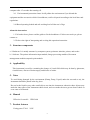
Chapter 1 Summarize
1. Brief Introduction
Projection perimeter,adopt the advantage of international advanced model, projection working
mode,with wide testing range 0-90°.It has the characteristics of full-function, high precision and
speed. Besides the above characteristics, the whole system also has the characteristic of high
dependability and steady performance. Software support Windows XP,WIN7 and Win 8 system
with easy operation interface. Kinds test program and strategy, standard test report and analysis
software, Provide auxiliary diagnosis for vision damage related diseases
2. Notice for use
2.1
For your security and benefit, please read the <Operation Instruction> as well as all the
datum of the instrument carefully before using it.If you do not operate the instrument according to the
Operation Instruction, we shall not take any responsibility.
2.2
Use it in a darkroom and it can only be operated by those who have been trained by
engineers of us.
2.3
The stimulus and PC system can be used in patient environment, printer should be used
outside of patient environment.
2.4
The voltage must be up to the given standard. If the voltage is not steady, please install a
Constant Voltage Regulator. We will not take responsibility for the damage caused by the voltage.
2.5
Do not use this instrument in the inflammable, hot and dusty environment and pay attention
to keep it clean and dry; To avoid being damaged by the environment (Damp, Dusty, Liquid, under
the sun and so on).
2.6
Do not let the liquid or any other small objects run into the instrument, otherwise these
objects may make the inner parts of the instrument short-circuit, and even make the users get an
electric shock or even cause a fire hazard.
2.7
Without the permission of us, do not open the box of the instrument or we will not take the
consequences
2.8
If you need restart the instrument,you can open the perimeter after 5 seconds and open the
4
computer after 15 seconds after turning off.
2.9
Environmental protection clause:It will pollute the environment if you discard the
equipment and the accessories which is breakdown, recall or disposal according to the local laws and
regulations.
2.10 Rated operating loaded and safe working load of chin rest is 5kgs.
About the instruction:
1. If it breaks down, please read the guide to fix the breakdown. If it does not work yet, please
contact us.
2. We have the right of interpreting and revising this operation instruction.
3. Structure components
a)Hardware: It’s mainly structure by computer system, perimeter stimulus, printer, and socket
b)Software: The patient information input module, Image processing modules, Document
management modules,output & print module:
4. Applicability
This instrument is used for examining the change of visual field which may be hurt by glaucoma,
visual disease, disease of brain surgery and disease of retina.
5. Notes
To avoid being damaged by the environment (Damp, Dusty, Liquid, under the sun and so on), the
instrument should be putted at the dry place.
Do not let the liquid or any other small objects run into the instrument, otherwise these objects may
make the inner parts of the instrument short-circuit, and even make the users get an electric shock or
even cause a fire hazard.
6. Manual
Effective for model: EPR-3600
7. Product features
Fusing parts: T2AL
250V
5
Security type:It belongs to B type instrument
The instrument is intermittent working form
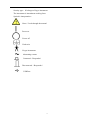
Symbolic interpretation:
Notes!Look through the manual
Power on
Power off
Earth wire
B type instrument
Alternating current
Connected(Responder)
Disconnected(Responder)
USB Port
6
Chapter 2 Technical Parameter
2.1 Technical Index
2.1.1 Background light
a) Background light:white, intensity 10 cd/m2。
b) Background light:yellow, adopt OG530 lens,intensity 100cd/m2。
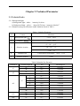
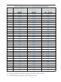
2.1.2 Stimulus testing, the allowance under limitation listed in Table 1.
Table 1: Stimulus Parameter
S/N
Content
Allowance
Background light,
1
+25%,-20%
Contrast,
2
+25%,-20%
0°~10°:≤0.5°
3
Stimulus location
10°~30°:≤1°
>30°:≤2°
4
Stimulus size
Conversion to solid angle:+20%,-15%
5
Stimulus duration
±20%
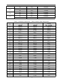
Table 2 Stimulus Size Paramter
Azimuth θ
eccentric angle Φ
b/a
solid angle Ω
15°
>0.7
6.66E-05
40°
>0.6
1.00E-04
15°
>0.7
8.00E-05
40°
>0.5
1.29E-04
Ⅰ
>0.7
2.50E-06
Ⅱ
>0.8
1.10E-05
Ⅲ
>0.8
6.50E-05
Ⅳ
>0.8
2.14E-04
Ⅴ
>0.8
6.50E-04
15°
>0.7
8.44E-05
40°
>0.6
1.10E-04
15°
>0.7
6.66E-05
40°
>0.6
1.15E-04
15°
>0.7
6.22E-05
0°
45°
2°
90°
135°
180°
7
225°
270°
315°
dB
40°
>0.6
9.00E-05
15°
>0.7
6.50E-05
40°
>0.6
7.99E-05
15°
>0.7
6.30E-05
40°
>0.6
7.20E-05
15°
>0.7
6.50E-05
40°
>0.6
9.20E-05
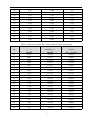
Table 3-1 Stimulus contrast ratio(White stimulus-White background)
Stimulus Intensity Ls LB
Luminance Ls
Contrast
0
3421.0
3431.0
342.10
1
2898.5
2908.5
289.85
2
2160.5
2170.5
216.05
3
1653.7
1663.7
165.37
4
1367.2
1377.2
136.72
5
1075.2
1085.2
107.52
6
854.73
864.73
85.47
7
674.10
684.10
67.41
8
547.33
557.33
54.73
9
426.74
436.74
42.67
10
333.40
343.40
33.34
11
270.32
280.32
27.03
12
234.00
244.00
23.40
13
200.65
210.65
20.06
14
159.60
169.60
15.96
15
110.21
120.21
11.02
16
90.47
100.47
9.05
17
63.50
73.50
6.35
18
50.24
60.24
5.02
19
40.82
50.82
4.08
20
31.85
41.85
3.18
21
25.69
35.69
2.57
22
20.26
30.26
2.03
23
16.59
26.59
1.66
24
12.70
22.70
1.27
25
10.05
20.05
1.00
26
8.10
18.00
0.81
27
6.86
16.86
0.69
8
28
5.06
15.06
0.51
29
4.10
14.00
0.41
30
3.19
13.19
0.32
31
2.57
12.57
0.26
32
2.00
12.00
0.20
33
1.60
11.60
0.16
34
1.27
11.27
0.13
35
1.00
11.00
0.10
36
0.80
10.80
0.08
37
0.64
10.64
0.06
38
0.50
10.50
0.05
39
0.40
10.40
0.04
Table 3-2 Stimulus contrast ratio(Blue stimulus-Yellow background)
dB
Stimulus Intensity
Ls LB
Luminance Ls
Contrast
0
65.34
165.34
0.6534
1
48.05
148.05
0.4805
2
39.98
139.98
0.3998
3
31.92
131.92
0.3192
4
25.52
125.52
0.2552
5
20.69
120.69
0.2069
6
16.92
116.92
0.1692
7
13.12
113.12
0.1312
8
10.31
110.31
0.1031
9
8.14
108.14
0.0814
10
6.34
106.34
0.0634
11
5.12
105.12
0.0512
12
4.24
104.24
0.0424
13
3.54
103.54
0.0354
14
2.76
102.76
0.0276
15
1.95
101.95
0.0195
16
1.51
101.51
0.0151
17
1.15
101.15
0.0115
18
0.89
100.89
0.0089
19
0.65
100.65
0.0065
20
0.52
100.52
0.0052
9
Table 3-3 Stimulus contrast ratio(Red stimulus-White background)
dB
Stimulus Intensity
Ls LB
Luminance Ls
Contrast
0
545.00
555.00
54.500
1
386.83
396.83
38.683
2
314.52
324.52
31.452
3
246.12
256.12
24.612
4
193.73
203.73
19.373
5
155.42
165.42
15.542
6
126.92
136.92
12.692
7
97.50
107.50
9.750
8
78.41
88.41
7.841
9
61.26
71.26
6.126
10
49.07
59.07
4.907
11
40.00
50.00
4.000
12
33.05
43.05
3.305
13
28.36
38.36
2.836
14
21.37
31.37
2.137
15
16.55
26.55
1.655
16
13.55
23.55
1.355
17
10.87
20.87
1.087
18
8.70
18.70
0.870
19
6.75
16.75
0.675
20
5.17
15.17
0.517
21
3.76
13.76
0.376
22
3.26
13.26
0.326
23
2.73
12.73
0.273
24
2.06
12.06
0.206
25
1.61
11.61
0.161
26
1.40
11.40
0.140
27
1.04
11.04
0.104
28
0.78
10.78
0.078
29
0.63
10.63
0.063
30
0.60
10.60
0.060
31
0.51
10.51
0.051
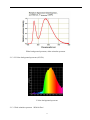
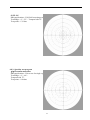
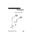
2.1.3 Spectral distribution of Background light and stimulus (white, red,blue)
2.1.3.1 White background spectrum, white stimulus spectrum
10
White background spectrum, white stimulus spectrum
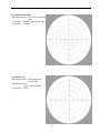
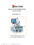
2.1.3.2 Yellow background spectrum (OG530)
Yellow background spectrum
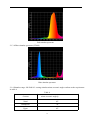
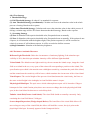
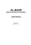
2.1.3.3 Red stimulus spectrum(RG610 filter)
11
Red stimulus spectrum
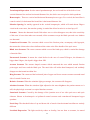
2.1.3.4 Blue stimulus spectrum (GG400)
Blue stimulus spectrum
2.1.4 Stimulus range: full field 90°,testing stimulus minus eccentric angle conform to the requirement
in table 4.
Table 4
Content
minus eccentric angle ф
Nasal
45°
Bitamporal
70°
Upper
45°
12
Under
60°
While testing,Nasal testing should be proceeded under Nasal step screening test mode.
Botamporal testing should be proceeded under FF135 Screening test mode. Upper and Under should
be proceeded under 60-4 threshold test mode.
2.1.5 Stimulus location amount and stimulation time:
a) Stimulus location amount: cannot less than the requirement listed in table 5
Table 5
Eccentric angle
ф
Minimum amount
0°~25°
60
>25°~50°
30
>50°~70°
15
Sum
105
b) Stimulus time of duration:
Kinetic:Movement speed:1°/sec-9°/sec adjustable
Move mode:Straight line
Sample:
Static:Stimulus time of duration 200ms
Stimulus interval:
1).If no response from patient, stimulus interval default as 1000ms;
2).If patient response,the system will adjust the stimulus interval according to the weighted
average of last 5 patient respond speed,if patient respond slow then the stimulus interval will be
automatically prolong. If patient respond fast then the stimulus interval will shorten automatically
2.1.6 The distance between patient eye and the fixation:300 mm±10 mm。
2.1.7 The instrument have head location device, and configure movable chinrest and forehead rest,
their travel distance from left-right ≥30 mm,and the chin rest of chinrest from up-down ≥50
mm.
13
2.1.8 This equipment configure auto calibration function for stimulus intensity, device will calibrate
the background intensity and stimulus intensity automatically while operator power on the equipment.
2.1.9 Input power:300VA。
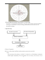
2.2 Flowchart
Stimulator
Responder
Computer
Display
Print
2.3 Working principle
The working principle of the perimeter is to examining the sensitivity of the human eye to light
stimulus which enable to check the lesions of optic nerve, retina, visual pathway etc. The ambient
light enter into retina by refraction system, then the retinal generate the photochemical reactions
which produce the bioelectrical which transmitted through the visual pathway to visual cortex, so that
the brain could generate the vision through a comprehensive analysis. Any part of the distribution and
the trend of the nerve fibers from the retina to the visual cortex could indicate the lesions which
happened on the visual pathway. The lesion part, the characteristic and prognosis can be all analyzed
by applying the clinic test results according to its visual transform.
14
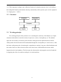
Chapter 3 Installation
1. Hardware
EPR-3600 projection perimeter have already been inspected and tested before leaving factory.
Please check if all accessories listed on list provided or not,any question, please contact with seller
immediately.
Please check accessories on list.
Stimulator
Computer
Picture of Whole instrument
▲ Main Spare-Parts
Printer
Responder
Stick
USB Wire
Power wire
15
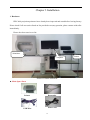
Printer
▲ The Front Picture of the Stimulator
Forehead Rest
Chin Rest
▲ The Back Picture of the Stimulator
Power On/Off
USB Port
Power Supply
2. Working Environment
Environment temperature:5℃-40℃
Relative humidity:≤85%
Atmospheric pressure range:760 hPa~1060 hPa
Power: a.c.100~240V;
Frequency:50Hz
Inputting power: 300VA
3. Installation environment
3.1 The instrument must be installed in the flat ground with no slope;
3.2 The instrument must be installed in the clean, quiet and dry room;
3.3
The instrument must be installed in the dark room where nothing can be seen within one
meter.
3.4 The instrument must be installed with special ground wire;
3.5 The instrument require the exclusive ground wire.
16
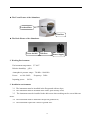
4.Hardware setup
4.1 Connect Perimeter and Computer with the new USB Serial Port Wires we provide.
Power on/off
Power supply
USB connecting
port
4.2 Connect the Power of the Perimeter.
4.3 Take out the fixed foam inside the Perimeter. Fix the Responder into the connector.
4.4 Connect the USB cable to computer, and install computer and printer accordingly.
5.Software setup
5.1 Windows System Requirements
English/ Simplified Chinese Version Window XP 32 bit Professional
English/ Simplified Chinese Version Windows 7 32bit/ 64bit Professional
English/ Simplified Chinese Version Windows 7 32bit/ 64bit Ultimate
or English/ Simplified Chinese Version Windows 8 32bit/64bit Professional
PS: Our perimeter software only support English/ Simplified Chinese Version Windows system,
if user running others language Windows system, there will be unreadable code showed during install
17
procedure and on software, or other unpredictable error will be occur. Please use relevant system we
recommended.
Please note the software will be default installed in folder C automatically.
5.2 Hardware Requirements
Before you install PERIMETER V-2.0, make sure your computer meets the following minimum
requirements:
*CPU
Mainboard: Intel chipset
Processor:≥1.7Ghz
multicore:Dual core,4 threaded.
* Memory minimum:≥2GB
* Hard disk
Rotational Speed:≥7200 RPM (Solid-state drives without this parameter)
Caching:≥2MB
Space:≥500GB
*Display
Supporting 1440 * 900 resolution or greater,1440 * 900 recommended.
Perimeter software show normally on resolution of:1440*900,1600*900,1920*1080.
* USB 2.0 Port
▲Make sure there are at least 2 partition “C:” and “D:” existing in the hard disk,
Otherwise the software will run error. Software will go wrong;
▲Make sure there is at least 5GB free space for data storage in partition “D”, otherwise the
software will go wrong.
5.3 After you install the computer system software, Insert install disk we provided into CD-ROM and
copy all the files we provide to your computer’s “D” partition, After the installation, please Do keep
the disc well !
5.4 Software installation procedure
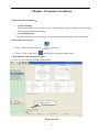
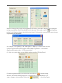
5.4.1 Install USB capture card driver for computer
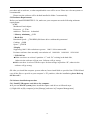
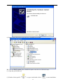
A:If you run Win XP system,please install the capture card driver as followed steps:
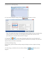
(1) Right click at [My computer],select [Manage] and enter in [Computer Management]
18
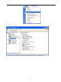
(2) Click at [Computer Management], And select [Imaging devices] in the right window.
(3) Right click at [USB Driver] and Click at“Update Driver”as followed pic.
19
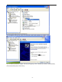
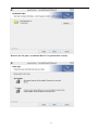
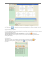
(4) A window will pop-up, select [Yes this time only],and continue by clicking [Next].
(5) A window [Hardware Update Wizard] will pop-up, select {Install the software automatically
[Recommended]},then click [Next]
20
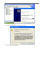
(6) A window pop-up like bellow, select [Continue Anyway]
(7) Click [Finish] to end the installation
21
(8) Image shows like below means the driver installed successfully.
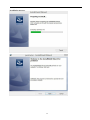
B: If you run Win7 system, please install the capture card driver as followed steps:
(1) Open the profile [Driver]
(2) Double click at profile
to open it and double click at
22
to start installation
(3) Click [Next] to continue,
(4).Click [Finish] icon, restart the computer.
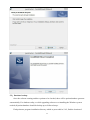
5.4.2 Open the file of perimeter software and double click on icon
23
to start the
installation process.
24
Relocate the file path, recommend Disc D:/ for patient data security.
25
5.5、Database backup
Once the software running and have patient to be checked, there will be patient database generate
automatically. For database safety, or while upgrading software or reinstalling the Windows system
needed,all patient database should be backup up as followed steps:
Find perimeter program installation directory which as proceeded in 5.4.2, find the location of
26
[Perimeter] file and open it,copy the file [dbfs] which is the database file and backup it safety.
Operator can recover the data by copy and paste this file back to [Perimeter] file and overwrite.
5.6 After the software installed, you rarely need to maintain it, if there is new software for update,
all you need to do is install the new software again.
Virus, serious wrong operate or hardware system failure may cause damage of the equipment, If
the software damaged seriously, please do as following step:
► Install operating system for computer, we suggest to use Windows XP Professional or Win7
► If the software cannot be identified automatically, please continue to finish the installation
manually
The drive program is located in the file our software disk provide.
Install 2860 video capture drive program, the drive program located in file our software disk
provide
27
Chapter 4 Function of software
1. Main function of software:
(1)Visual Checking
The main functions of this module are for: visual checking, statistic analysis of the checking
result, storing the data and printing;
(2)2 File Management
The main functions are: file searching, report comparison and printing, document deleting;
2. Start and close software
(1)Start:Double click the icon of
(2)Close:Click on the icon of
on desktop
which locate at the upper-right corner
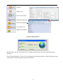
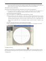
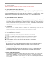
3. Introduction of the Operation System
(1) There are five interface of EPR-3600 software.
3D Image preview
Home interface
28
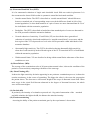
Interface Bar: Back to Home interface, Back to
Examination interface, User-define test interface, Printing, System setting and About us
Patient info area: Recheck (the same eye of same patient) , Edit,
Delete(Selected patient data), All patient list, Last record
Waiting area: Register new patient, Start check, Edit, Delete
Monitoring
Window
Chin Rest
Control
Gaze Tracking
Curve
Testing interface
[NEW] Auto pupil monitoring – The system
will adjust the chinrest automatically
according to pupil monitoring-Doctors do not
need to monitor the whole testing after
starting the test
29
Start test
Stop the test
Save the test result
Setting the parameter
Select test program
Test another eye
Diagnosis inputting
System setting interface
Double Name: For EU, USA and AUS. etc market which need the first name and family name
inputting.
Gaze Tracking/EyeMove: Tick on for activating the gaze tracking function which will generate gaze
tracking curve and Auto pupil measurement function.
30
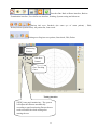
User-defined test interface
Firstly please click the bottom left
in the interface to set up a new programme, then
input the programme name, and click
to save the defined programme as following
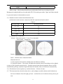
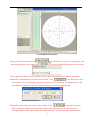
The second step is:There are four method to choose the dot position for user defined programme
Method One: Stationing the test dots as with circular, Click
to input the inner circle
and external circle scope and the space between dots, the unit will be the centrifugal degree, after
input all these information, the dots will be generated automatically as following
Method Two:Stationing the test dots with rectangle, Click
to input the coodinate
degree of opposite angles of the rectangle, and the space between dots, the unit will be the
centrifugal degree, after input all these information, the dots will be generated automatically as
31
following:
Method Three: Input the coordinate degree inside of the X and Y coordinate bar directly, the unit will
be the centrifugal degree, after input the coordinate degree click
Method Four: Click
“test scope”
as following:
, setting “test scope” first and then the centrifugal degree of
And then click the testing dots you want to choose directly as shown below:
32
(2)Several important programs and parameters of visual testing
First choose a Testing Program (threshold test, screen test, special, custom). Once the program is
selected, go to the Parameter to choose a Strategy (full threshold, auto threshold, fast auto
threshold) accordingly.
4. Operation Step
The doctor’s Preparation
The patient’s preparation
Patient’s examination
Treating after examination
Print report
5. Doctor’s Preparation
5.1 Power on the perimeter and Enter into the perimeter system as the way in 5.2;
Notes:
After powering on the perimeter, it will take 3~4 minutes for a self-checking by running the
stimulus lights automatically. This will guarantee the test accuracy. Do not treat it as an
33
system error and do not enter into testing procedure while self-checking in processing, the
system will not run correctly. Enter the testing only after self-checking finished.
5.2 Input the patient’s information;
5.3 Operator should inform patient the examination process before the examination:
1) The patient should be familiar with the responder: demonstrate him the right way of
responding, the way of clicking the responder, and make him relax as soon as possible.
2) Demonstration him the fixing sight
3) Cover the patient’s eye which will not be tested with an eye shroud.
4) Put the patient’s jaw on the right side of the chin rest when examining the left eye; put the
patient’s jaw on the left of the chin rest when examining the right eye. If the patient testing
Esterman binocular program, patient can either put their chin on left or right chinrest, but
doctor need to adjust the cross in monitoring window aimed at center of patient’s nose
bridge.
5) Put his forehead on the ribbon of the forehead bracket slightly.
6) The eyeball shall stare at the center fixation light, and cannot move, only glance to perceive
the stimulus light and respond to it by pressing the responder
6. Starting Checking
6.1 Before you start the test, you should Click the Register[
] icon on the main interface to setup
the patient profile and input the info of patient, a patient profile will be saved automatically after you
clicking [Save] .
34
Patient with myopia, hyperopia and astigmatism will need to correct their diopter before starting the
testing, our perimeter set trial lens holder for this function. Click on the icon of [
] and inputting
patient’s real refractive diopter, then click on the [Auto Calc] to get the corrected lens you need to put
on perimeter trial lens holder.
For example, if we inputting -5.0D under Sphere of Right eye, click on Auto Calc, the
system will generate the corrected lens need to adapt for patient is -1.75D. Doctor
should test the patient with a -1.75D corrected lens.
6.2 After save patient data, you can find the patient record at [Waiting Room].
Click on the patient colume you wish to enter, and click on [
] enter the testing
Interface. The default testing program is 30-2,and strategy is auto threshold, if you
want to change to other program, click at the
, select the program
35
you want to use as following image.
Or, if you want to change the strategy, click at
and choose as below
Notes: The program and strategy will automatically resume to default value once currently testing
finished. System will not memory your last program and strategy setting. Operator need to
proceed this process if default value needed to be changed.
6.3 Then click
to start testing. During the testing, doctor can use the function of
[Auto Puil] monitoring so that do not need to monitor the whole process personally. The system will
adjust the chinrest the headrest automatically.
6.4 [Pause] and [Stop] testing
During testing , operator can Pause and Stop testing by clicking icon locate at right side of tesing
interface.
6.5 After testing, you should save the test result by clicking at
diagnosis.
36
and then you can
6.6 Click at the
, choose the test report you need and preview. There are Single, 3in1, and
Overview test report optional.
6.7 If your patient have come to you and test for several times, you should use the Overview report to
see the progressing of patient.
For doing more than one test with a same patient, you should click
to proceed.
For GPA analysis, at least 3 reports of (24-2 or 30-2) of same client shall be generated before
running this function.
6.8 Patient List
Through this section, you can delete a patient profile by clicking the icon of
,and
find/recall a patient profile by clicking the icon of
after you inputting the
keywords
37
6.7 Test report reliability
Number of testing dots means the total number of testing dots of the perimeter
(1). False Negative Errors (False NEG Errors):
False Negative errors occur when the patient does not respond to a suprathreshold stimulus in an
area where the threshold has already been measured. The interpretation of false-negative errors is not
as clear as that of false-positive ones, because they can be produced by a variety of sources. Visual
field test results of patients whose false negative errors exceed 33% are not considered reliable.
(2). False Positive Errors (False POS Errors):
False positive errors occur if patients respond when no stimulus is presented. For the purposes of
this study, we define a false positive response as randomly occurring, independent of stimulus
presentation, and hence independent of any monitored response window. The system will count it
and if it’s over 20%, the test report will be treated as unreliable. Visual field test results of patients
whose false positive errors exceed 33% are not considered reliable.
(3). Fixation Loss
Fixation losses occur when the patient’s eye wanders from the fixation target. Visual field test
results of patients whose fixation losses exceed 20% are not considered reliable.
(4). Percentage(Expressed as Letter P)
Less than 5 people within 100 people have this kind of visual situation
Less than 2 people within 100 people have this kind of visual situation
Less than 1 people within 100 people have this kind of visual situation
Less than 0.5 people within 100 people have this kind of visual situation
(5). Total deviation
The difference between a patient’s threshold sensitivity and the age-corrected normal sensitivity
from the perimeter’s internal normative database at each tested location of the visual field.
(6). Pattern deviation (PD)
The localized loss at each tested point, after the removal of the effects of any generalized loss;
pattern deviation decibel (dB) values are the total deviation values minus the general value
(7).Pattern standard deviation (PSD)
It is a measurement of the degree which the shape of the patient's measured field or hill of vision
departs from the "NORMAL" age-corrected reference field model. The value is expressed in
decibels and any value of 2dB or greater will have a (P) value next to it indicating the significance
of the deviation
38
(8). Glaucoma Hemifield Test (GHT):
It is for automated evaluation of single static threshold visual field test results in glaucoma. It is
also constructed to detect field loss that is symmetric around the horizontal meridian.
Outside normal limits. The GHT is described as “outside normal limits” when differences
between a matched pair of corresponding zones exceeds the difference found in 99% of the
normal population, or when both members of a pair of zones are more abnormal than 99.5% of
the individuals with the normative population.
Borderline. The GHT is described as borderline when matched pairs of zones are abnormal at
the 97th percentile within the normative database
General reduction of sensitivity. Visual Fields (VF) are described to have generalized
reduction of sensitivity when both conditions for “outside normal limits” are not met, and the
best region of the VF is depressed to a level at the 99.5th percentile within individuals of the
normative database.
Abnormally high sensitivity. The GHT is described as having abnormally high sensitivity
when the overall sensitivity in the affected region of the VF is better than 99.5% of individuals
within the normative population.
Within normal limits. VFs are described as being within normal limits when none of the above
conditions are met.
(9).Mean Defects: (MD):
The average of the examination value of all spots minus normal value, it shows the condition of the
patient’s vision sensitivity comparing with those of the same age.
(10). Short Floating (SF):
It shows the light sensitivity deviation appearing in one perimeter examination process; it shows the
reaction consistency in the course of examining. The bigger the value is, the worse the cooperation
the patient shows. The short wave will become height in the scope of abnormal visual field. When
more scope in the visual field become abnormal or the degree of abnormal increases, the whole
wave will become higher.
(11).Decibel (dB)
In perimetry, the intensity of a stimulus expressed as 0.1 log-unit of attenuation of the maximal
available stimulus; the higher the dB, the dimmer the stimulus intensity.
(12).Fixation monitoring
Assessing the ability of the patient to maintain gaze by the experimenter’s observation.
39
6.8 Introduction of test parameter
6.8.1. Threshold test program:
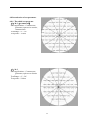
(1)30-2(recommend)
Main applications:Common test,
glaucoma, optic nerve disease,
retinal disease
Test Range:0°~30°
Test points:76 dots
(2)24-2
Main applications:Common test,
glaucoma, optic nerve disease
Test Range:0°~24°
Test points:54 dots
40
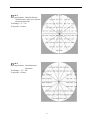
(3)10-2
Main applications:Macular disease,
retinal disease, optic nerve disease,
advanced glaucoma
Test Range:0°~10°
Test points:68 dots
(4)60-4
Main applications:Retinal disease,
glaucoma
Test Range:30°~60°
Test points:60 dots
41
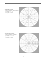
(5) Macula program:
Main applications:Macular disease
Test Range:0°~5°
Test points:16 dots
(6) Nasal step program:
Main applications:Glaucoma
Test Range:30°~50°
Test points:14 dots
42
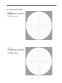
6.8.2. Screening test program
(1) C-40
Main applications:Common test
Test Range:0°~30°
Test points:40 dots
(2) C-76
Main applications:Common test,
glaucoma, optic nerve disease
Test Range:0°~30°
Test points: 76 dots
43
(3) FF-81
Main applications:Full-field screening
test, retinal disease, glaucoma,
optic nerve disease
Test Range:0°~60°
Test points:81 dots
(4) FF-120
Main applications:Full-field screening
test, retinal disease, glaucoma,
optic nerve disease
Test Range:0°~60°
Test points:120 dots
44
(5)FF-135
Main applications:Full-field screening test
Test Range:0°~55°,Temporal side 87°
Test points:135 dots
6.8.3. Specialty test program
(1)Esterman monocular
Main applications:Driver test for single eye
Test Range:0°~60°,
Temporal side 75°
Test points:100 dots
45
(2) Esterman binocular
Main applications:Driver test for double
eyes
Test Range:Double temporal side 150°
Test points:120 dots
(3) Superior 36
Main applications:Screening upper
visual field
Main applications:
upper visual field 60°
Test points:36 dots
46
6.8.4 Test Strategy
1. Threshold Strategy
(1) Full Threshold Strategy: It adopt 4-2 as standard for response
(2) Auto Threshold Strategy (recommend): Calculate and correct the stimulate value in the whole
process of testing. Based on the response
(3)Fast Auto Threshold Strategy: Calculate and correct the stimulate value in the whole process of
testing, variation range will be 50% faster than auto threshold strategy, Based on the response
2.Screening Strategy
(4) Zone 2: Stimulate with superior threshold value, Responded treat as normally
(5) Zone 3: Stimulate with superior threshold value, Responded treat as normally. If the patient do not
response, it will stimulate with the brightest light, If the patient responsed, it will be recorded as
relatively scotoma, if still without response, it will be recorded as definite scotoma
(6)Single Stimulate: Stimulate with stationary brightness
6.8.5 Perimeter Academic Discourse
Different Light Threshold: Under the circumstance of stationary lighting, if the stimulate spot
visibility is 50%, then this spot stimulate intensity will be different light threshold
Vision Island: The altitude means light sensitivity, the area means the islands scope, image the visual
field as an island in the sea, every spots of the retina will corresponding a position on the island, The
spots fixation spot which is the macular area with highest sensitivity, constitute the peak of the island,
and the around area the sensitivity will be lower, which constitute the circum area of the vision island.
Visual Isopter: The vertical height of the spot on vision island means the visual acuity, the lines on
the same vertical height is the isoheight, in visual foeld the name is isopter.
Physiological Blind Spot: The optic nerve which without photoreceptor cell is located at 15degree
bitamporal of the visual fixation point, there area can not see things, that is the physiological blind
spot, in the visual island its shown as a vertical deep hole.
Tubular visual filed(Center visual island): The visual field shrink to centrality extremely. Only
remaining the visual field about 5-10degree
Sector-shaped Depression (Wedge-shaped Defect): The board line of the visual field defect will
move along two ways of the visual field, the defect will look like a sector, the tip is point to the
physiologic blind spot. Its meanly appeared in the bitamporal defect
47
Tetarfanopia Depression: Its also named quadrantanopia, the two board line of the defect is one
vertical diameter line and one horizontal diameter line, the defect area occupied a whole quadrant
Hemoanopia:There are vertical and horizontal hemoanopia two types. For vertical, the board line is
central vertical, for horizontal the board line is horizontal diameter line
Macular Sparing: Its mainly appeared in the vertical hempanopia, which will retain about 5degree
visual at the center area, the macular sparing is remind the defect location is at visual pay-off
Scotoma:Means the abnormal visual field reduce area or vision disappear area, that is the sensitivity
of this area is lower than other area around, all the scotomas except the blind spot and verse shadow
are abnormal
Centralcecal Scotoma: The scotoma which covered the fixation point, accompany with hypopsia,
that means the sickness have been influenced the retina or the fibre bundle of the optic nerve
Blind Area Scotoma: The center scotoma which covered the bind spot, which is remind the damage
of macular fibre
Paracentral Scotoma: It means the visual defect in the area of center5-25degree, the diameter is
bigger than 5degree, the depth is bigger than 5dB
Arcuate Scotoma: The arcuate shaped scotoma which connected the area which around fixation
point upper and lower and the blind spot. The nasal side will wider than bitamporal, and suddenly
disappear at horizontal meridian line
Ring Scotoma: The connected the horizontal joint of upper and lower arcuate scotoma surround nasal
side of central fixation area
Relative Scotoma: When the stimulate light get stronger, the scotoma will disappear
Absolute Scotoma: When the stimulate light adjusted to the most brightness the patient cannot see it
still, the physiologic scotoma is a topical absolute scotoma
Junctional Scotoma: Caused by the damage of the junction area of one side optic nerve and optic
chiasma. Shown as hemianopsia at ipsilateral central scotoma and contralateral bitamporal upper
quadrant
Nasal Step: The threshold value of up and down side of nasal vision horizontal meridian are entirely
different
Localized Depression: The light sensitivity reduce at locality, but not form to scotoma, its named
48
localized depression, its shown as visual isopter localized depression which is different to scotoma,
the scotoma are surrounded by relatively normal vision field, but at least one direction of the localized
depression without clearly board line(Normally its telecentric direction ). Nasal step, bitamporal
visual isopter and wedge-shape depression are the typical localized depression
Generalized Depression: Light sensitivity of entire visual field consistency decline. When use
kinetic checking it shows all visual isopter shrink centripetalism, when use static checking it shows
the dB value decline consistency, the threshold value is generally higher
6.8.6 Data Recover and Backup
1. Medical record(Test report) backup
The software will be default installed in C:\Perimeter, and the data will be stored in
C:\perimeter\dbfs. For most of time, the system is safe and reliable
But as the report is very important, to avoid lose data because of virus or computer failure, we
advice to backup the the report data weekly or monthly
Backup method: Quit from the perimeter software, copy the whole folder of C:\perimeter\dbfs
and paste it to the target folder, we suggest to discs data and label the date on it
2. Medical record(Test report ) recover
Normally you don’t have to recover the data, But sometimes the computer may broken because of
virus and system failure, you have to format folder C which will lead to data lose while reinstall the
system, after fixed the computer you have to reinstall the system and recover the data from the back
up folder.
Firstly select the one you want to recover from the back up, copy and paste them to the same folder of
C:\perimeter
49
Chapter 5 Maintenance
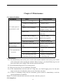
5.1 Common Problems
Breakdown
Cause
Treating methods
Failed to setup USB device
Re-set USB device
Voltage isn’t enough or too
Replace power
high
Can’t start system or
Memory lost or damaged
system doesn’t work
Insert again or replace the
computer memory card
Infect virus
Use anti-virus software to
scan virus
Crashes while working or
show that the program is wrong.
Open too many
application programs,
re-start the computer
Hard disk is damaged
Replace the hard disk
Nothing in the screen
LCD monitor doesn’t display any
Properly connect the wire,
when opening it
image
switch on power
Connection wire is damaged
The responder does
not work
Replace the Connection
wire
Pressing button is damaged
Replace the pressing key
The controlling card in the
Replace or maintain the
stimulator does not work
controlling card
5.2 Maintenance
5.2.1 You should firstly turn on the power switch of the monitor and then turn on the power switch
of the main frame when opening the machine. When closing it, you should firstly log out, and
then turn off the power supply of the monitor and the main frame.
5.2.2 Scan disk and arrange pieces in a certain period.
5.2.3 Keep air clean, dry; use air-conditioner if possible
5.2.4 If the instrument has not been used for a long time, you should supply power for the main
frame at intervals. (Usually three times a week, four hours one time)
5.2.5 If there is something wrong with the instrument, please contact us immediately or ask the
special maintainers to maintain.
Notes: You should clean the chin rest before and after each time you use it.
5.3 Fusing Parts:
50
Model of fuse: φ5×20mm, T2A L250V
Replace the fuse: Screw off the cover of fuse, replace it with a new good fuse, then cover again
(see the picture of the perimeter)
Chapter 6 Declarations
We can provide you with the information of those parts need maintained.
1. We will provide maintenance and enquiry free for one life.
2. We will maintain the machine for free for one year since the date of purchasing if the machine is
operated according to the operation instruction.
3. During the maintenance, we will charge fee for the maintenance under the following conditions
● Do not use, maintain, store the instruments according to operation instruction;
● Take apart or amend the instruments without the permission of us, which cause damage;
● Damages is caused by accidents, use wrongly or caused by other major nature factors.
● Please forgive us for not informing you if the design or the assigned type changes.
51
52