1
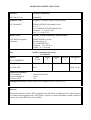
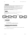
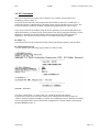
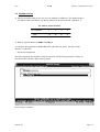
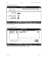
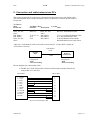
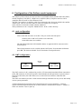
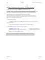
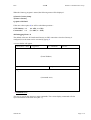
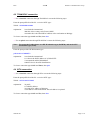
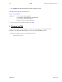
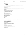
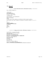
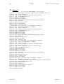
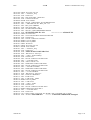
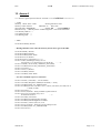
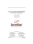
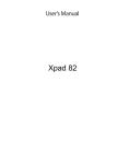
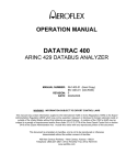
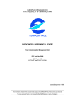
EUROPEAN ORGANISATION
FOR THE SAFETY OF AIR NAVIGATION
EUROCONTROL EXPERIMENTAL CENTRE
Satfone Communication set up
User Manual
EEC Note N° 1/96
EEC Task N° AT51
EATCHIP Task Specification FCO.ET3.ST02
Approved for publication by
Head of Division B2
Issued : January 1996
The information contained in this document is the property of the EUROCONTROL Agency and no part should
be reproduced in any form without the Agency's permission.
The views expressed herein do not necessarily reflect the official views or policy of the Agency
REPORT DOCUMENTATION PAGE
Reference :
Security Classification :
EEC Note N° 1/96
Unclassified
Originator Code :
Originator (Corporate Author) Name/Location :
EEC Division B2
EUROCONTROL Experimental Centre
B. P. 15
F 91222 BRETIGNY SUR ORGE Cedex
Telephone + 33 1 69.88.75.00.
Fax + 33 1 69.88.73.33.
Sponsor Code :
Sponsor (Contract Authority) Name/Location :
EATCHIP Development
Directorate
EUROCONTROL Agency
Rue de la Fusée, 96
B 1130 BRUXELLES
Telephone + 32 2 729 90 11
Telefax +32 2 729 90 44
Title :
Satfone Communication set up
User Manual
Authors :
Mr. G. RAMBAUD
Date
Pages
Figures
Annexes
References
01/1996
33
3
4
4
EATCHIP Ref.:
EEC Task N°.:
FCO.ET3.ST02
AT51
Distribution Statement :
(a) Controlled by
(b) Special limitations
(c) Sent to NTIS
:
:
:
Task N°. Sponsor :
Period :
10/95 - 01/96
Head of Division B2
None
No
Descriptors Keywords : Satfone model, SDU equipment, Data-3 Gateway, X25.
Abstract :
This note discribes the Avionics DTE configured as a PAD and the configuration of an AES composed
of a Satfone model equipment and a SITA Data-3 Gateway to obtain a downlink or uplink connection
between an Avionics DTE and a Ground DTE.
EEC Note N° 1/96
EEC Task N° AT/51
Issued : January 1996
Satfone Communication set up
User Manual
by
G. RAMBAUD
Summary
This note discribes the Avionics DTE configured as a PAD and the configuration of an AES composed of
a Satfone model equipment and a SITA Data-3 Gateway to obtain a downlink or uplink connection
between an Avionics DTE and a Ground DTE.
Table of contents
LIST OF ABBREVIATIONS ...........................................................................................................2
GLOSSARY......................................................................................................................................2
REFERENCES .................................................................................................................................2
1. INTRODUCTION.........................................................................................................................3
2. PURPOSE .....................................................................................................................................3
2.1 AES DESCRIPTION .........................................................................................................................3
3. CONFIGURATION OF THE PC “AVIONICS DTE”................................................................3
3.1 X.PAD WITH WINDOWS.................................................................................................................4
3.2 EC COMMANDS .............................................................................................................................5
3.3 HARDWARE SET UP .........................................................................................................................6
3.4 SOFTWARE SET UP ........................................................................................................................10
4. CONFIGURATION OF THE PC “SITA DATA-3 GATEWAY”.............................................10
4.1 FUNCTIONALITY ..........................................................................................................................10
4.2 EC COMMANDS ...........................................................................................................................10
4.3 HARDWARE SET UP .......................................................................................................................11
4.3.1 ARTIC-429 Card Installation ...............................................................................................11
4.3.2 EiconCard Installation.........................................................................................................12
4.4 SOFTWARE SET UP ........................................................................................................................16
5. CONNECTION AND CABLE BETWEEN TWO PCS.............................................................17
6. CONFIGURATION OF THE SATFONE MODEL EQUIPMENT..........................................18
6.1 RACK CONFIGURATION .................................................................................................................18
6.2 CMT CONFIGURATION .................................................................................................................18
7. CONFIGURATION OF THE COM PORTS JUST FOR THE PC “AVIONICS DTE”..........19
8. CONNECTION START UP .......................................................................................................20
8.1 INTRODUCTION : ..........................................................................................................................20
8.2 START UP.....................................................................................................................................20
8.3 PAD START UP “AVIONICS DTE” .................................................................................................21
8.4 DATA-3 GATEWAY EXECUTION ON THE PC “SITA DATA-3 GATEWAY” .........................................22
8.5 TRANSPAC CONNECTION...........................................................................................................25
8.6 SITA CONNECTION ......................................................................................................................25
9. STOPPING THE PAD................................................................................................................26
10. ANNEX 1...................................................................................................................................27
11. ANNEX 2...................................................................................................................................28
12. ANNEX 3...................................................................................................................................29
13. ANNEX 4...................................................................................................................................31
EEC
V 1.00
Satfone Communication set up
List of Abbreviations
ADS
AES
Automatic Dependent Surveillance
Aircraft Earth Station
AOR-East
Atlantic Ocean Region-East
ASAP
ARTIC Software Application Program
CMT
Commissioning Maintenance Terminal
D/LNA
Duplexer/Low Noise Amplifier
DNIC
Data Network Identification Code
DTE
Data Terminal Equipment
EC
EiconCard
GES
Ground Earth Station
HPA
High Power Amplifier
IRQ
Interrupt Request
LGA
Low Gain Antenna
NCB
Network Control Block
PAD
Packet Assembler Disassembler
RFU
Radio Frequency Unit
SCM
System Control Module
SDM
System Definition Manual
SDU
Satellite Data Unit
SITA
Society International of Telecommunications Aeronautics
TSR
Terminate and Stay Resident
Glossary
SATFONE
Data-2
Data-3
RACAL AES equipment (Data 2 compatible)
INMARSAT Standard on AES equipment
INMARSAT Standard on AES equipment
References
1.
2.
3.
4.
EiconCard/PC 1MB Installation Guide 203-011-2
OSI GATEWAY Reference Guide Version 3, Release 1
Satellite AIRCOM Data-3 Gateway User’s Guide Revision 4 Ref : 3225/PM/DCGI37/92
Software System Functional Specification for the Aviation Satellite Communication
System
manual.doc
Page n° 2
EEC
V 1.00
Satfone Communication set up
1. Introduction
This booklet describes the realisation of a connection between the AES located at Brétigny and
the Aussaguel GES located in the South of France via an INMARSAT satellite.
The communication between AES and GES follows the INMARSAT protocols defined in the
INMARSAT System Definition Manual (SDM).
The aim is to obtain a downlink connection established on the avionics request to the earth
station, and an uplink connection established on the earth station request to the avionics.
It is necessary to use a Data-3 Gateway between the Avionics DTE and the SDU Data-2 to
establish an end-to-end X.25 communication.
This documentation is only available for Satfone model equipment.
2. Purpose
Configuration of an AES and set up for a connection to a GES “AUSSAGUEL” via a
communication satellite.
The following figure shows how the modules are linked together.
Satellite
Figure n°1
Avionics
DTE
P
A
D
X.25
SITA
DATA-3
GATEWAY
RACAL
(SDU) Equip.
429
AES Brétigny
Application
Ground
DTE
GES
Aussaguel
X.25
Network / SITA or TRANSPAC
Aussaguel
DTE Brétigny
2.1 AES description
The AES is composed of :
• a PC “Avionics DTE”,
• a PC “SITA Data-3 Gateway” SITA owns the software,
• a RACAL Data-2 “SDU” equipment (SATFONE model).
3. Configuration of the PC “Avionics DTE”
The avionics DTE includes :
• an EICON card for an X.25 connection to the PC “SITA” (Ref : EiconCard/PC 1MB).
This DTE is configured as a PAD (Figure n°2).
manual.doc
Page n° 3
EEC
V 1.00
Satfone Communication set up
3.1 X.PAD with Windows
With Windows, you should set up your terminal emulation to use specific COM ports
(terminal emulation written for Windows probably will not offer other choices). An additional
driver in the X.PAD package, X25COM.DRV, provides a run-time link that services both
X.PAD and serial drivers used by Windows.
The diagram below shows the standard serial communications scheme under Windows. The
terminal emulation program uses the Windows Application Program Interface (API) to
communicate with the serial COM ports.
The API is a series of Dynamic Link Library (DLL) functions designed for all Windows
applications that want to do serial communications. These functions are linked to the
application program at run-time.
The Eicon Technology driver (X25COM.DRV) is integrated into the Windows environment so
that it is linked with both the API and the serial driver. It intercepts all the standard serial
function calls and then redirects them to the appropriate driver.
If the data is for a serial COM port, then X25COM will send it to the normal serial driver.
Data directed to a COM port designated for X.25 communications will be sent to the X.PAD
module and from there to the EiconCard X.25 Gateway.
Figure n°2
Terminal Emulation
Application Program Interface
X 25 COM.DRV
Serial
Driver
X.PAD
Serial
Port
X.25
EiconCard
Serial and X.25 Communications
Remark : The EC commands are a group of programs that allow to control OSI PC Gateway
functions [Ref. 2]. Run them from the command line or in batch files to start and
stop the gateway, and obtain status and statistics.
The EiconCard/PC 1 MB is a sophisticated communications card that allows (with the
appropriate software) to link to X.25 network.
manual.doc
Page n° 4
EEC
V 1.00
Satfone Communication set up
3.2 EC Commands
The Eicon commands are used to start, configure, test, examine, and stop the Eicon
Technology Gateway [Ref. 2].
Test of the EiconCard with a test program (ECTEST.EXE) in directory c:\OSIGATE. It
verifies the integrity of the hardware component of the gateway through a series of tests. The
EiconCard must be configured with the configuration program before it can be tested.
If you try to run ECTEST without using the /FOrce parameter on an EiconCard that has an
application running, a warning will be issued and no tests will be performed. When the /FOrce
parameter is used, the EiconCard is halted without warning and ECTEST performs its
diagnostics. The EiconCard software must be re-loaded when testing is complete.
ECTEST /FO
Forces deactivation of any loaded EiconCard without warning the operator, and tests them.
ECTEST Display Screen
A screen similar to the following appears when you run ECTEST.
You must re-start the PC “Avionics DTE” to re-load the EiconCard software.
Each time an EiconCard is tested, the validity of its configuration (EiconCard type, I/O
Address, Memory Segment and IRQ) is verified. If a configuration error is detected, no further
tests are performed until a correct EiconCard configuration is created with the configuration
program (ECCFG) [Ref. 2].
manual.doc
Page n° 5
EEC
V 1.00
Satfone Communication set up
3.3 Hardware set up
♦ The EiconCard/PC 1MB can use one of seven standard I/O Addresses. The default setting is
I/O Address 380h. Switch SW1 sets the I/O address for the EiconCard/PC 1MB [Ref. 1].
I/O Address Switch Positions
I/O ADDRESS
380h
1
2
3
4
off
off
on
on
♦ Memory segment address at 0D000 using IRQ 5
To configure these parameters run ECCFG.EXE, and follow the panels. This file is in the
directory c:\OSIGATE.
⇒ EiconCard configuration
The following panels are snapshots of the EiconCard ECCFG.EXE program [Ref. 2].They are
presented in the order they appear in the program.
Press F4 key to continue.
manual.doc
Page n° 6
EEC
V 1.00
Satfone Communication set up
Hardware Configuration Screen
Press F4 key to continue.
Protocol Configuration Screen
On the Line protocol module select X.25 then press F4 key to continue.
manual.doc
Page n° 7
EEC
V 1.00
Satfone Communication set up
X.25 Configuration Screen (Sequential VC)
Press F4 key to continue.
HDLC Configuration Screen
Press twice F3 key to get back the Protocol Configuration Screen. On the Dialer selection line
select Direct then press F4 key to continue.
manual.doc
Page n° 8
EEC
V 1.00
Satfone Communication set up
Direct Dialer Configuration Screen
Press F4 key to continue.
Sync Driver Configuration Screen
Press F10 key to quit.
manual.doc
Page n° 9
EEC
V 1.00
Satfone Communication set up
3.4 Software set up
♦ The PAD will run under Windows, therefore the two following programs are needed.
• X25COM.DRV, in directory c:\osigate. It is the X25 communications driver.
• METHOD.EXE, in directory c:\osigate. It is the COM Port Method Utility.
♦ To load the PAD, ECXPAD.INI file is necessary in directory c:\osigate.
The ECXPAD.INI file determines the initial configuration of the X.PAD driver
(ECXPAD.EXE), as well as such aspects of the X.PAD environment as the size of the working
buffers and the communications interrupt that the driver uses [Ref. 2].
♦ Config.sys and Autoexec.bat of the PC “Avionics DTE” are given in Annex 1.
4. Configuration of the PC “SITA data-3 Gateway”
4.1 Functionality
The Data-3 gateway provides the following functions :
Perform the ISO 8208 InterWorking Function as specified in Inmarsat SDM CN 56
Appendix 10. This allows the Gateway to establish, maintain and clear virtual
connections (VCs) and relay data between the satellite Sub-Network and X.25
network.
The Data-3 GATEWAY PC has for this reason been fitted with two communication cards :
•
•
an ARTIC 429 Receive/Transmit Interface card.
an EiconCard/PC 1MB X.25 Interface card with OSI-PC Gateway software.
4.2 EC Commands
The Eicon commands are used to start, configure, test, examine, and stop the Eicon
Technology Gateway [Ref. 2].
Test of the EiconCard with a test program (ECTEST.EXE) in directory c:\OSIGATE. It
verifies the integrity of the hardware component of the gateway through a series of tests. The
EiconCard must be configured with the configuration program before it can be tested.
If you try to run ECTEST without using the /FOrce parameter on an EiconCard that has an
application running, a warning will be issued and no tests will be performed. When the /FOrce
parameter is used, the EiconCard is halted without warning and ECTEST performs its
diagnostics. The EiconCard software must be re-loaded when testing is complete.
manual.doc
Page n° 10
EEC
V 1.00
Satfone Communication set up
ECTEST /FO
Forces deactivation of any loaded EiconCard without warning the operator, and tests them.
ECTEST Display Screen
A screen similar to the following appears when you run ECTEST.
You must re-start the PC “SITA Data-3 Gateway” to re-load the EiconCard software.
Each time an EiconCard is tested, the validity of its configuration (EiconCard type, I/O Address,
Memory Segment and IRQ) is verified. If a configuration error is detected, no further tests are
performed until a correct EiconCard configuration is created with the configuration program
(ECCFG) [Ref. 2].
4.3 Hardware set up
4.3.1 ARTIC-429 Card Installation
Switches configuration of the card for this Address 0D000 (S1) and jumpers configuration for
an Interrupt Request Level IRQ5 (JP5).You can see the hardware configuration figure n°3.
Note : This configuration cannot be changed. It is up to verify that no other device in the
PC is conflicting with these options.
manual.doc
Page n° 11
EEC
V 1.00
Satfone Communication set up
ARTIC-429-Card View from Above
BMC HAL3 REV 1.4
P1
P2
(Not used)
Figure n°3. S1 Memory Address Swith and JP5 IRQ jumper
4.3.2 EiconCard Installation
The EiconCard/PC 1MB can use one of seven standard I/O Addresses. The default setting is
I/O Address 380h. Switch SW1 sets the I/O address for the EiconCard/PC 1MB [Ref. 1].
Switch positions
I/O ADDRESS
380h
1
2
3
4
off
off
on
on
♦ Memory segment address at 0D800 using IRQ 3
To configure these parameters run ECCFG.EXE, and follow the panels. This file is in the
directory c:\OSIGATE .
manual.doc
Page n° 12
EEC
V 1.00
Satfone Communication set up
⇒ EiconCard configuration
The following panels are snapshots of the EiconCard ECCFG.EXE program with the
configuration used by the Data-3 Gateway with OSI Gateway V3R1.25.They are presented in
the order they appear in the program [Ref. 2].
Press F4 key to continue.
Hardware Configuration Screen
Press F4 key to continue.
manual.doc
Page n° 13
EEC
V 1.00
Satfone Communication set up
Protocol Configuration Screen
On the Line protocol module select X.25 then press F4 key to continue.
X.25 Configuration Screen (Sequential VC)
Press F4 key to continue.
manual.doc
Page n° 14
EEC
V 1.00
Satfone Communication set up
HDLC Configuration Screen
Press twice F3 key to get back the Protocol Configuration Screen. On the Dialer selection line
select Direct then press F4 key to continue.
Direct Dialer Configuration Screen
Press F4 key to continue.
manual.doc
Page n° 15
EEC
V 1.00
Satfone Communication set up
Sync Driver Configuration Screen
Press F10 key to quit.
4.4 Software set up
Config.sys and Autoexec.bat of the PC “SITA Data-3 Gateway” are given in Annex 2.
manual.doc
Page n° 16
EEC
V 1.00
Satfone Communication set up
5. Connection and cable between two PCs
This section describes how to connect two EiconCards back-to-back using a null modem cable.
The following table shows which null-modem cables you should use to connect specific kinds of
EiconCards.
To connect
these
EiconCard
DNA, EC, NA,
SPCC
HSI, DPNA
HSI, DPNA
DNA, EC, NA,
SPCC
Via thisTo these
interface
EiconCards
RS-232-C
V.24 or V.35
X.21
V.24
Use this
cable
DNA, EC, NA,
SPCC
HSI, DPNA
HSI, DPNA
HSI, DPNA
RS-232-C Null-Modem Cable.
V.24 / V.35 HSI Null-Modem Cable.
X.21 HSI Null-Modem Cable.
V.24 HSI Modem Cable,with the
HSI Null-Modem Conversion Cable.
A RS-232-C Null-Modem Cable can be used to connect the PC ‘avionics DTE” and the PC
“SITA Data-3 Gateway”.
Null-Modem
Cable
SITA
DATA-3
GATEWAY
Avionics
DTE
X.25
Configuration :
- DCE
- External Clocking
Configuration :
- DTE
- Internal Clocking
Pin-out diagrams for a null-modem cable:
•
The RS 232 C Null -modem cable connects an EiconCard to another EinconCard,
using an RS 232 C interface.
DB-25 Male
DB-25 Male
1
3
2
8
1 PGND
2 TxD
3 RxD
4 RTS
5 CTS
6 DSR
7 SGND
8 DCD
15 TxCLK
17 RxCLK
20 DTR
24 CLK
20
7
4
5
24
6
15
17
RS-232-C Null-Modem Cable
manual.doc
Page n° 17
EEC
V 1.00
Satfone Communication set up
6. Configuration of the Satfone model equipment
The Satcom system consists of a RACAL Data-2 (SATFONE model) Satellite Data Unit (SDU),
a Radio Frequency Unit (RFU), a High Power Amplifier (HPA), a Duplexer and Low Noise
Amplifier (D/LNA) and Low Gain Antenna (LGA).
The SDU can connect to 4 satellites, it has been connected to the closest one which is the satellite
Atlantic East. The user can ask to SDU to connect to another one if required.
Some trials have been made with the satellite AOR-East.
These parameters are in a script file “Buildc58.EEC” in the c:\SDU directory.
6.1 rack configuration
Value of the SDU discretes are 80 Hex. They are on the rack front panel.
switches SW1 to SW7 OFF (SW8 is not connected)
switch SW9 data/voice on Data.
The 38017B Hexadecimal AES identifier address is applied to SK52 connector on the
rack font panel.
These both parameters can be verified with the CMT menu. From the Main SCP Menu
press E/F (E /Software Module Test, F /Production Test Specification).
6.2 CMT configuration
RS-232
Cable
SDU
equipment
Terminal
DEC VT-100
The CMT consists of a PC configured to provide a VT100 terminal emulation.When connected to
SCM_XB connector of AES rack (System Control Module Port B equivalent to System Control
Processor of the SDU), the CMT allows access to the CMT user interface within the SDU
software.
The CMT user interface provides a menu structure through which the user may access and modify
various system parameters.
All the informations about menus can be found in RACAL Avionics document <<Software
System Functional Specification for the Aviation Satellite Communication System>> (chapter 4,
CMT user interface -issue 5) [Ref. 4].
manual.doc
Page n° 18
EEC
V 1.00
Satfone Communication set up
The PC works under MS Windows in DEC VT-100 (ANSI) terminal emulation :
Menu << setting >>
Communications
Baud Rate....................19200 Bauds
Data Bits......................8 Bits
Stop Bits......................1 Bit
Parity............................None
Flow Control................Xon/Xoff
Connector.....................COM1
RS 232 link between the PC COM1 and the AES rack SCM_XB.
RS-232 cable :
COM1 (DB 9)
SCM_XB (DB 25)
2 Rx.....................................................2 Tx
3 Tx.....................................................3 Rx
5 Gnd...................................................7 Gnd
Note: The AES is configured in Automatic Log on.
7. Configuration of the COM Ports just for the PC “Avionics DTE”
1 In the X25 Communication window, choose the Method icon.
2 The COM Port Method window appears.
This shows what communications method each COM port is currently using; serial or X.25.
manual.doc
Page n° 19
EEC
V 1.00
Satfone Communication set up
Ø Explanation of COM Port Method Utility software:
This utility lets you change the communications method of the COM ports from X.25 to serial
and back again while Windows is running.
8. Connection start up
8.1 Introduction :
The objectif of this chapter is to obtain a Log-on with a GES (AUSSAGUEL).There is a SDU
Log file in Annex 3 and a Gateway Log file in Annex 4.
To get a connection Uplink or Downlink, execute the following steps.
•
•
•
•
•
Start up
PAD start up “Avionics DTE”
Data-3 Gateway execution
Uplink or Downlink TRANSPAC connection (X.25 Network)
Uplink or Downlink SITA connection (X.25 Network)
8.2 Start up
To start the RACAL SDU equipment (SATFONE model) it is just necessary to switch on the
rack to perform a log-on.
Both the avionics DTE and the Data-3 Gateway must be switched on together. Normally, when
you start the PCs the following EC Commands are include in the AUTOEXEC.BAT file.
CD \OSIGATE
ECBIOS START /Int 5A /Pool 20
ECCARD START /M 16 /NCB 16
You need to have a screen similar to the following appearing on the two PCs.
manual.doc
Page n° 20
EEC
V 1.00
Satfone Communication set up
Ø Explanation of the commands in AUTOEXEC.BAT
ECBIOS.EXE for DOS
ECBIOS.EXE is a program that must be loaded to operate the DOS gateway. This program links
the gateway PC to the EiconCard contained within. (It is a TSR acting as a device driver.)
ECBIOS START /Int 5A /Pool 20
This command starts ECBIOS, it uses interrupt 5A for operation under Microsoft Windows, and
reserves a buffer pool 20K for all sessions originating from the gateway.
ECCARD START /M 16 /NCB 16
This command loads and starts the EiconCard. ECCARD is executed after ECBIOS is loaded,
and must be run to operate the gateway. The size (M) of the MAIL trace buffer and the size (Ncb)
of the NCB trace buffer on the EiconCard, in kilobytes. This is used to perform an internal mail
trace and an internal NCB trace.
The Eicon Technology Gateway uses Network Control Bloks (NCBs) to communicate with the
EiconCard.
8.3 PAD start up “Avionics DTE”
The X.PAD icon is under the X.25 Communication Windows
1 Start the X.PAD under DOS
ECXPAD START (This executable is in this directory c:\OSIGATE) [Ref. 2].
2 Run Windows.
3 In the X.25 Communication window, choose the X.PAD icon.
The prompt XPAD will appear (XPAD :)
manual.doc
Page n° 21
EEC
V 1.00
Satfone Communication set up
8.4 Data-3 Gateway execution on the PC “SITA Data-3 Gateway”
You must start the Gateway after “Logged on” is obtained by the SDU.
ECMODULE is used to examine the protocol information streaming through the Eicon
Technology Gateway, and to provide statistical information about the various connections. The
information is obtained directly from the appropriate EiconCard Loadable Module (ELM).
We can used here before starting the gateway the ECTRACE command.
The ECTRACE utility provided with Eicon’s software permits to keep a trace of the X.25
packets that are exchanged by the EiconCard and the network. To use this facility with the
Gateway, the following steps must be executed.
1- Enable tracing by typing :
ECMODULE TRACE X25 /S 32000 /T 259 (in the directory c:\OSIGATE) [Ref. 2]
2- Start the Gateway :
Gateway (This executable file is in this directory c:\GATEWAY) [Ref. 3]
3- After quitting the gateway----get the X.25 trace by typing :
ECMODULE TRACE X25
ECMODULE TRACE X25 > X25TRACE.TXT
<- to display at the screen [Ref. 2]
<- to send to X25TRACE.TXT file
Redo step 1 to reinitialise the trace buffer.
Note : If you want execute the Data-3 Gateway without X.25 Trace run step 2.
manual.doc
Page n° 22
EEC
V 1.00
Satfone Communication set up
When the Gateway program is started, the following menu will be displayed :
S) Data-3 Gateway Setup
T) Data-3 Gateway
Q) Quit to MS-DOS
If the user selects option S, he will be asked three questions :
GTW Identity = 0
Connected to = 0
(0= AES, 1 = GES)
(0 = SDU, 1 = STE)
429 Debugging Menu = 0
The default values are AES mode and Gateway to SDU connection. Once the Gateway is
configured, its main menu can be activated by typing T.
A screen similar will appear.
GTW(AES)<->SDU
Logged On
Tr = 00000000
Inactive
(Event Window)
Input : CONSOLE
Log : Off
>_
(Command Area)
⇒ Command Area :
This area is used by the operator to enter commands. The various display commands will also
report information in the same area [Ref. 3].
manual.doc
Page n° 23
EEC
V 1.00
Satfone Communication set up
⇒ Event Windows :
This is where most of the action will occur. This window will display all traceable events as
they happen [Ref. 3].
All events have the following formats :
HH:MM:SS.CC Object Comment
Where HH:MM:SS.CC is the timestamp indicating when the associated event occurred,
“Object” is an indication of where the action occurred and “Comment” is a description of what
occurred.
Start the Data-3 Gateway by typing start. Then a screen similar will appear.
GTW(AES)<->SDU
Logged On
Tr = 00000000
0 VC Active
(Event Window)
14:35:16.38 Gateway Started
Input : CONSOLE
Log : Off
> start
>_
(Command Area)
Now you can have an uplink or a downlink connection through TRANSPAC or SITA.
Note : If an AES Logoff event occurs, the Gateway closes all active VCs.
manual.doc
Page n° 24
EEC
V 1.00
Satfone Communication set up
8.5 TRANSPAC connection
⇒ For a downlink connection through TRANSPAC execute the following steps:
From the prompt XPAD of the PC “Avionics DTE” type :
XPAD : call 0208091109606
explanation :
0 to obtain the international
2080 this is the country code (France) DNIC
91109606 this is the TRANSPAC address of the workstation at Brétigny
To clear a connection type Ctrl P and Esc, then clear.
⇒ For an uplink connection through TRANSPAC execute the following steps:
Note : To execute the PAD software on a HP Workstation type (PADEM), and on the SUN
Workstation type (PAD).
From the prompt of the HP Workstation type :
padem 01111516000573
explanation :
0 to obtain the international
1111 that is the DNIC address of AUSSAGUEL
5 Aeronautical mobile INMARSAT
16000573 this is the AES identification
To clear a connection type Ctrl P and Enter, then quit.
8.6 SITA connection
⇒ For a downlink connection through SITA execute the following steps:
From the prompt XPAD of the PC “Avionics DTE” type :
XPAD : call 26111623323985
explanation :
26 prefix
1116 DNIC address
2332398 SITA address of Brétigny
5 sub-address of the workstation. The sub-address is optional.
To clear a connection type Ctrl P and Esc, then clear.
manual.doc
Page n° 25
EEC
V 1.00
Satfone Communication set up
⇒ For an uplink connection through SITA execute the following steps:
From the prompt of the HP Workstation type :
padem 01111516000573
explanation :
0 it is to obtain the international
1111 that is the DNIC address of AUSSAGUEL
5 Aeronautical mobile INMARSAT
16000573 this is the AES identification
To clear a connection type Ctrl P and Enter, then quit.
9. Stopping the PAD
Do not stop X.PAD from within Windows. X.PAD is a resident program, and like all resident
programs, if it is unloaded while Windows is active it will cause Windows to crash.
At the DOS command prompt, you can type the following:
ECXPAD STOP ALL
manual.doc
Page n° 26
EEC
V 1.00
Satfone Communication set up
10. Annex 1
************** Autoexec.bat file of the PC “Avionics DTE” ****************
@ECHO OFF
C:\DOS\SMARTDRV.EXE /X
PROMPT $P$G
rem c:\vif\scan c: /clean
PATH C:\OSIGATE;C:\BC4\BIN;C:\WINDOWS;C:\EICON\X25WIN\DLL;C:\DOS;C:\MFT;
SET TEMP=C:\TEMP
NLSFUNC
MODE CON CODEPAGE PREPARE = ((850) C:\DOS\EGA.CPI)
MODE CON CODEPAGE SELECT = 850
KEYB US,,C:\DOS\KEYBOARD.SYS
C:\WINDOWS\mouse.COM /Y /S70
DOSKEY
VER
REM EICON statements begin
CD C:\OSIGATE
ECBIOS START /Int 5A /Pool 20
ECCARD START /M 16 /NCB 16
REM EICON statements end
pause
ecxpad start
cd ..
pause
win
************** Config.sys file of the PC “Avionics DTE” ****************
DEVICE=C:\DOS\SETVER.EXE
DEVICE=C:\DOS\HIMEM.SYS
DEVICE=C:\DOS\EMM386.EXE RAM X=D000-D1FF
DOS=HIGH,UMB
COUNTRY=001,850,C:\DOS\COUNTRY.SYS
FILES=40
BUFFERS=20
rem DEVICE=C:\DOS\ANSI.SYS /x
DEVICE=C:\DOS\DISPLAY.SYS CON=(EGA,,2)
rem DEVICE=C:\WINDOWS\IFSHLP.SYS
STACKS=9,256
manual.doc
Page n° 27
EEC
V 1.00
Satfone Communication set up
11. Annex 2
*********** Autoexec.bat file of the PC “SITA Data-3 Gateway” *************
rem c:\windows\smartdrv.exe
@ECHO OFF
set PROMPT=$p$g
rem c:\vif\scan c:\ /clean
set temp=c:\windows\temp
c:\dos\mouse.com
rem set comspec=c:\dos\command.com
rem call c:\lanwp.bat
doskey
set path=c:\dos;c:\ads;c:\windows;c:\tcwin\bin;c:\bc4\bin;c:\osigate;c:\gateway;
rem set path=c:\dos;c:\ads;c:\windows;c:\net\net\bin;c:\tcwin\bin;c:\bc4\bin;c:.;f:.;x:.;y:.;z:.;
c:\
rem win
ecbios start /Int 5a
eccard start /M 16 /NCB 16
cd gateway
pause
gateway
cd ..
*********** Config.sys file of the PC “SITA Data-3 Gateway” *************
rem DEVICE=C:\DOS\SETVER.EXE
shell=c:\dos\command.com /p /E;1536
STACKS=9,256
DEVICE=C:\DOS\HIMEM.SYS
DEVICE=C:\DOS\EMM386.EXE X=D800-DFFF
DEVICE=C:\DOS\ANSI.SYS
DOS=HIGH,UMB
FILES=50
BUFFERS=20
REM TEST UN
rem device=c:\windows\ifshlp.sys
rem ce=c:\dos\display.sys con=(EGA,437, 1)
rem CE=C:\PLUGPLAY\DRIVERS\DOS\DWCFGMG.SYS /NOLOCK
manual.doc
Page n° 28
EEC
V 1.00
Satfone Communication set up
12. Annex 3
00:07:09.9
00:07:10.0
00:07:10.1
00:07:11.1
00:07:11.7
00:07:11.7
00:07:11.8
00:07:13.5
00:07:13.5
00:07:13.5
00:07:13.6
00:07:23.6
00:07:23.6
00:07:23.7
00:07:23.7
00:07:24.8
00:07:24.8
00:07:25.4
00:07:25.4
00:07:25.5
00:07:27.9
00:07:28.0
00:07:28.0
00:07:28.0
00:07:38.1
00:07:38.1
00:07:38.1
00:07:38.2
00:07:38.3
00:07:38.3
00:07:39.4
00:07:39.4
00:07:40.0
00:07:40.0
00:07:40.1
00:07:46.5
00:07:46.5
00:07:46.5
00:07:46.6
00:07:56.6
00:07:56.6
00:07:56.6
00:07:56.7
00:07:56.8
00:07:57.3
00:07:57.3
00:07:57.4
00:07:57.4
00:07:59.8
manual.doc
************** SDU log-file ****************
User : UsMn: In State <UNAVAIL_ON_HOOK> Stim <ATTEMPT_LOG_ON>
ALO : Sat Id 0 Preference 1
ALO : Sat Id 0, Longitude -54, Elevation 13, RamThreshold 5
ALO : TX INHIBIT STATE = 0x
BTMD : Tx Freq 36E3x
BTMD : Rx Freq 36B8x
ALO : SATSEARCH AWAIT SIGNAL FOR SAT ID 00x PSMC 1x
FSPM : Rx InLock
FSPM : First Lock on P-Ch
RXCH : PLS->Demod
ALO : >- SIGNAL_ACQ
ALO : DSS = 2920 DNF = 1776 Signal Quality = 2ABC70x
ALO : SIGNAL_ACQ FOR SAT 0 = 2800752
ALO : Sat Id 1 Preference 2
ALO : Sat Id 1, Longitude -15, Elevation 29, RamThreshold 5
ALO : TX INHIBIT STATE = 0x
FSPM : Rx Lock LOST
BTMD : Tx Freq 36E3x
BTMD : Rx Freq 32BEx
ALO : SATSEARCH AWAIT SIGNAL FOR SAT ID 01x PSMC 1x
FSPM : Rx InLock
FSPM : First Lock on P-Ch
RXCH : PLS->Demod
ALO : >- SIGNAL_ACQ
ALO : DSS = 2803 DNF = 1429 Signal Quality = 2DEBC2x
ALO : SIGNAL_ACQ FOR SAT 1 = 3009474
ALO : Sat Id 2 Preference 1
ALO : Sat Id 2, Longitude 178, Elevation -45, RamThreshold 5
ALO : Sat Id 3 Preference 1
ALO : Sat Id 3, Longitude 64, Elevation 7, RamThreshold 5
ALO : TX INHIBIT STATE = 0x
FSPM : Rx Lock LOST
BTMD : Tx Freq 36E3x
BTMD : Rx Freq 32E6x
ALO : SATSEARCH AWAIT SIGNAL FOR SAT ID 03x PSMC 1x
FSPM : Rx InLock
FSPM : First Lock on P-Ch
ALO : >- SIGNAL_ACQ
RXCH : PLS->Demod
ALO : DSS = 2761 DNF = 2063 Signal Quality = 48162Ex
ALO : SIGNAL_ACQ FOR SAT 3 = 4724270
ALO : SATSEARCH SAT 01x PREF 2 SIGNAL-QUALITY-VALUE 3009474
ALO : SEARCH FREQ FOR SAT 01x
FSPM : Rx Lock LOST
ALO : START tA13
ALO : STATE 0 AWAIT P-CH SYNC
BTMD : Tx Freq 36E3x
BTMD : Rx Freq 32BEx
FSPM : Rx InLock
Page n° 29
EEC
00:07:59.8
00:07:59.9
00:07:59.9
00:07:59.9
00:07:59.9
00:08:00.0
00:08:00.0
00:08:01.1
00:08:01.1
00:08:01.1
00:08:01.2
00:08:01.2
00:08:01.2
00:08:01.3
00:08:01.8
00:08:01.9
00:08:01.9
00:08:01.9
00:08:02.0
00:08:03.7
00:08:03.7
00:08:03.7
00:08:03.7
00:08:03.8
00:08:03.8
00:08:03.8
00:08:03.8
00:08:03.9
00:08:03.9
00:08:09.9
00:08:09.9
00:08:09.9
00:08:10.0
00:08:10.5
00:08:10.6
00:08:10.6
00:08:11.2
00:08:11.2
00:08:11.3
00:08:11.3
00:08:11.3
00:08:11.4
00:08:11.4
00:08:11.4
00:08:11.4
00:08:11.5
00:08:11.5
00:08:15.9
00:08:15.9
00:08:15.9
00:08:16.0
manual.doc
V 1.00
Satfone Communication set up
FSPM : First Lock on P-Ch
ALO : >- SIGNAL_ACQ
ALO : STOP tA13
ALO : SET R1 IN PMA - SEND ALL
ALO : SATELLITE ID 01x
RXCH : PLS->Demod
ALO : STATE 1 AWAIT REV_NO IN BROADCAST
ALO : >- BROADCAST SU : REV_NO : 21x
ALO : REV_NO CURRENT
ALO : SET R1 IN PMA : 21x
ALO : NO SPOT BEAM TABLE
ALO : GES ID := FIRST PREFERRED GES ID
<------------------ AUSSAGUEL
ALO : SELECTED GES ID : 43x
FSPM : Rx Lock LOST
ALO : TUNE TO Psmc/Rsmc OF SELECTED GES
ALO : START tA13
ALO : STATE 2 AWAIT P-CH SYNC
BTMD : Tx Freq 36B6x
BTMD : Rx Freq 36B6x
FSPM : Rx InLock
FSPM : First Lock on P-Ch
RXCH : PLS->Demod
ALO : >- SIGNAL_ACQ
ALO : STOP tA13
ALO : AES TYPE IS VOICE2/DATA2
ALO : WrPowerVar : Init Eirp 3
ALO : -> TRG : LOG-ON-REQ
ALO : START tA11
ALO : STATE 4 AWAIT LOG-ON-CONF
ALO : >- LOG-ON CONF
ALO : AES CLASS IS : 01x
ALO : SOME MSG ACK FLAGS ZERO
ALO : STATE 4 AWAIT LOG-ON-CONF
ALO : >- P/R-CH CONTROL
ALO : SOME MSG ACK FLAGS ZERO
ALO : STATE 4 AWAIT LOG-ON-CONF
ALO : >- T-CH CONTROL
ALO : WrPowerVar : Init Eirp 3
ALO : STOP tA11 B000001x
ALO : R-CH TUNE
ALO : P-CH TUNE : 36B6x
BTMD : Rx Freq 36B6x
ALO : T-CH TUNE
ALO : -> TRG : ACKo
ALO : START tA12
ALO : STATE 5 AWAIT LOG-ON ACKo
BTMD : RBurst Freq 36E3x Rate 1
ALO : >- LOG-ON ACKo
ALO : STOP tA12
User : UsMn: In State <UNAVAIL_ON_HOOK> Stim <LOGGED_ON_CLASS1>
<-------- Connection establish with Aussaguel
ALO : STATE 6 LOGGED-ON
Page n° 30
EEC
V 1.00
Satfone Communication set up
13. Annex 4
**** Events Log File opened 95/09/22 10:04:48 ****** GATEWAY************
> config
Gateway Mode: AES<->SDU
Routing Initiation: None
Gateway Status: Inactive
SDUMon=5s
Retry=60s
429 Link Status: Logged On
GESid=103
AESid=16000573
Default Priority = 7 Facility Mask = 0xffff Diagnostic = 0x93 0x26 0x00 0x00
X.25 Primary Address = ''
X.25 Address Prefix = ''
X.25 Routing DTE = ''
> start
10:05:06.38 Gateway Started
; Routing Initiation starts when the Gateway detects the Logon of the SDU.
10:05:06.38 BGF() Started
10:05:06.38 IWF(0) Started
10:05:06.38 IWF(0) State: IDLE
10:05:06.38 VC( 0) Started
10:05:06.38 X25(?) x25xlisten(r=*, l=*)
10:05:17.32 Rx( 0) CREQ(01) ch(2), len=15
01 02 a0 01 11 15 96 98 06 02 33 01 00 0b 00
..........3....
10:05:17.32 BGF() Event: SNS_CONNECT_IND (0202)
10:05:17.32 IWF(0) Event: SNS_CONNECT_IND (0202)
10:05:17.32 priority=7
10:05:17.38 VC( 1) Started
10:05:17.38 IWF(1) Started
10:05:17.38 IWF(1) State: IDLE
; Now the X.25 DTE requests a connection
10:05:17.38 X25(?) x25xcall(r=, l=0111159698)
10:05:17.38 Call(0) Requested SSND(0111159698) -> X.25()
10:05:17.38 IWF(0) State: VC_INDICATION
10:05:17.43 IWF(0) Event: X.25 Post: cid=1, cmd=0, info=0x00, ret=0x00, len=0
c=0x00, d=0x00
10:05:17.49 priority=7
10:05:17.49 VC( 0) HLE->: SNS_CONNECT_RSP usrlen=0
10:05:17.49 Tx( 0) CCNF(09) ch(2), len=7
09 02 04 0b 00 02 33
......3
10:05:17.49 Call(0) Connected
10:05:17.49 IWF(0) Initializing Data Transfer
10:05:17.49 IWF(0) Initializing Receive buffers
10:05:17.49 X25(1) x25recv(503)=0, err=0
10:05:17.49 VC( 0) HLE->: SNS_RX_DATA_REQ len=503
10:05:17.49 IWF(0) State: VC_CONNECTED
10:05:17.60 Tx(LS)=0
manual.doc
Page n° 31
EEC
V 1.00
Satfone Communication set up
10:05:41.98 Rx( 0) DATA(30) ch(2), no=0, len=15
30 02 00 54 68 65 20 71 75 69 63 6b 20 62 72
0..The quick br
10:05:41.98 IWF(0) Event: SNS_RX_DATA_CMP (0f02)
10:05:41.98 X25(1) x25send(12, 0)=0, err=0
10:05:41.98 IWF(0) Event: X.25 Post: cid=1, cmd=3, info=0x00, ret=0x00, len=12
c=0x00, d=0x00
54 68 65 20 71 75 69 63 6b 20 62 72
The quick br
10:05:41.98 VC( 0) HLE->: SNS_RX_DATA_REQ len=503
10:05:47.98 Rx( 0) DATA(30) ch(2), no=1, len=15
30 02 01 54 68 65 20 71 75 69 63 6b 20 62 72
0..The quick br
10:05:47.98 IWF(0) Event: SNS_RX_DATA_CMP (0f02)
10:05:47.98 X25(1) x25send(12, 0)=0, err=0
10:05:48.05 IWF(0) Event: X.25 Post: cid=1, cmd=3, info=0x00, ret=0x00, len=12
c=0x00, d=0x00
54 68 65 20 71 75 69 63 6b 20 62 72
The quick br
10:05:48.05 VC( 0) HLE->: SNS_RX_DATA_REQ len=503
10:05:54.05 Rx( 0) DATA(30) ch(2), no=2, len=15
30 02 02 54 68 65 20 71 75 69 63 6b 20 62 72
0..The quick br
10:05:54.05 IWF(0) Event: SNS_RX_DATA_CMP (0f02)
10:05:54.05 X25(1) x25send(12, 0)=0, err=0
10:05:54.05 IWF(0) Event: X.25 Post: cid=1, cmd=3, info=0x00, ret=0x00, len=12
c=0x00, d=0x00
54 68 65 20 71 75 69 63 6b 20 62 72
The quick br
10:05:54.05 VC( 0) HLE->: SNS_RX_DATA_REQ len=503
10:06:20.32 Rx( 0) DATA(30) ch(2), no=3, len=26
30 02 03 54 68 65 20 71 75 69 63 6b 20 62 72 6f 0..The quick bro
77 6e 20 66 6f 78 20 6a 75 6d
wn fox jum
10:06:20.38 IWF(0) Event: SNS_RX_DATA_CMP (0f02)
10:06:20.38 X25(1) x25send(23, 0)=0, err=0
10:06:20.38 IWF(0) Event: X.25 Post: cid=1, cmd=3, info=0x00, ret=0x00, len=23
c=0x00, d=0x00
54 68 65 20 71 75 69 63 6b 20 62 72 6f 77 6e 20 The quick brown
66 6f 78 20 6a 75 6d
fox jum
10:06:20.38 VC( 0) HLE->: SNS_RX_DATA_REQ len=503
10:06:27.71 Rx( 0) DATA(30) ch(2), no=4, len=26
30 02 04 54 68 65 20 71 75 69 63 6b 20 62 72 6f 0..The quick bro
77 6e 20 66 6f 78 20 6a 75 6d
wn fox jum
10:06:27.71 IWF(0) Event: SNS_RX_DATA_CMP (0f02)
10:06:27.76 X25(1) x25send(23, 0)=0, err=0
10:06:27.76 IWF(0) Event: X.25 Post: cid=1, cmd=3, info=0x00, ret=0x00, len=23
c=0x00, d=0x00
54 68 65 20 71 75 69 63 6b 20 62 72 6f 77 6e 20 The quick brown
66 6f 78 20 6a 75 6d
fox jum
10:06:27.76 VC( 0) HLE->: SNS_RX_DATA_REQ len=503
10:06:34.38 Rx( 0) DATA(30) ch(2), no=5, len=26
30 02 05 54 68 65 20 71 75 69 63 6b 20 62 72 6f 0..The quick bro
77 6e 20 66 6f 78 20 6a 75 6d
wn fox jum
10:06:34.38 IWF(0) Event: SNS_RX_DATA_CMP (0f02)
10:06:34.38 X25(1) x25send(23, 0)=0, err=0
10:06:34.38 IWF(0) Event: X.25 Post: cid=1, cmd=3, info=0x00, ret=0x00, len=23
c=0x00, d=0x00
54 68 65 20 71 75 69 63 6b 20 62 72 6f 77 6e 20 The quick brown
66 6f 78 20 6a 75 6d
fox jum
manual.doc
Page n° 32
EEC
V 1.00
Satfone Communication set up
10:06:34.43 VC( 0) HLE->: SNS_RX_DATA_REQ len=503
10:06:43.98 Rx( 0) RSET(33) ch(2), c=07, d=26, len=4
33 02 07 26
3..&
10:06:43.98 VC( 0) Remote Reset
10:06:43.98 IWF(0) Event: SNS_R_RESET_IND (1202)
10:06:43.98 IWF(0) SNS Reset(1202) c=07, d=26
10:06:43.98 X25(1) x25reset(c=07, d=26)
10:06:44.05 IWF(0) State: VC_RESET
10:06:44.05 IWF(0) Event: X.25 Post: cid=1, cmd=10, info=0x02, ret=0x00, len=2
c=0x00, d=0x00
00 00
..
10:06:44.05 VC( 0) HLE->: SNS_RESET_RSP
10:06:44.10 Tx( 0) 10:06:44.10 IWF(0) Initializing Receive buffers
10:06:44.10 X25(1) x25recv(503)=-1, err=261
RCNF(3b) ch(2), len=2
3b 02
;.
10:06:44.10 VC( 0) HLE->: SNS_RX_DATA_REQ len=503
10:06:44.10 IWF(0) State: VC_CONNECTED
10:06:44.16 Tx(LS)=0
; The Ground DTE now clears the connection
10:07:04.32 Rx( 0) CREL(10) ch(2), c=00, d=99, len=4
10 02 00 99
....
10:07:04.32 VC( 0) Remote Clear
10:07:04.32 IWF(0) Event: SNS_R_DISCONNECT_IND (0702)
10:07:04.32 IWF(0) SNS Remote Clear(0702) c=00, d=99
10:07:04.32 VC( 0) HLE->: SNS_DISCONNECT_RSP
10:07:04.32 Tx( 0) CCMP(18) ch(2), len=2
18 02
..
10:07:04.32 X25(1) x25hangup(c=00, d=99)
10:07:04.38 IWF(0) State: VC_CLEAR
10:07:04.38 IWF(0) Event: X.25 Post: cid=1, cmd=7, info=0x00, ret=0x0a, len=0
c=0x00, d=0x00
10:07:04.38 IWF(0) Event: X.25 Post: cid=1, cmd=8, info=0x23, ret=0x00, len=0
c=0x00, d=0x00
10:07:04.38 Call(0) Cleared
10:07:04.38 IWF(0) State: VC_TERMINATED
10:07:04.43 Tx(LS)=0
10:07:05.38 BGF() Event: BGF_FREE_IWF (0017)
; Finally, the gateway is stopped by the operator.
> stop
10:56:26.16 Gateway Stopped
10:56:26.16 BGF() Event: Destroy (0103)
10:56:26.16 X25(0) x25cancel()
10:56:26.16 IWF(1) Event: Destroy (0103)
10:56:26.16 IWF(1) Local Clear(0103) c=85, d=e2
10:56:26.16 IWF(1) State: VC_TERMINATED
> quit
**** Events Log File closed 95/09/22 10:56:12 ****
manual.doc
Page n° 33