1
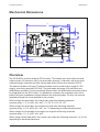
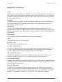
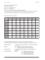
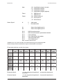
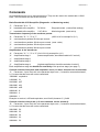
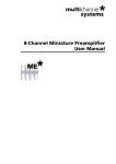
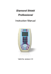
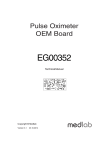
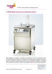
Medlab GmbH
EG12000 User Manual
medlab
Twelve Lead
ECG OEM board
EG12000
Technical Manual
Copyright © Medlab 2013
Version 1.05
1
Version 1.05
EG12000 User Manual
Version 1.05
Medlab GmbH
2
Medlab GmbH
EG12000 User Manual
Table of Content
Mechanical Dimensions
4
Overview
4
Definition of Terms
5
Module Connectors
7
Physical Units of Transmitted Data
7
Technical Data
8
Connectors
9
ECG Cable Coding
10
Compliance with IEC60601-2-27
11
Serial Transmission
13
Software Protocol Description
14
Introduction
14
Packet Description
16
Commands
20
PC Test Program
21
Regulatory Considerations
22
Revisions of this document
23
3
Version 1.05
Medlab GmbH
EG12000 User Manual
Mechanical Dimensions
88
33,1
18,5
JP1
JP3
13
2,2
2,54
5,08
JP6
53
47
JP2
8,3
2,5
1,6
74,5
Mechanical drawing, top view of the module (DXF data available upon request)
Overview
The EG12000 is a twelve channel ECG module. The module can work with a ten lead
cable to show 12 channels, with a five lead cable showing 7 channels, with a four lead
cable showing 6 channels and with a three lead cable to show one channel of ECG.
The board includes a full type CF patient isolation and is powered by a single 5 V DC
supply, consuming less than 250 mW. The limb leads (see page 5 for definition) are
defibrillation protected. For the remaining Wilson leads, the defibrillation protection has to
be integrated into the ECG cable. It is possible to measure the respiration rate of the
patient using the impedance change between the limb electrodes. For this, the optional
respiration board has to be attached to the module.
When using a ten lead cable, the module can output the following channels
synchronously: I, II, III, aVR, aVL, aVF, C1, C2, C3, C4, C5, C6.
When using a five lead cable, the module can output the following channels
synchronously: I, II, III, aVR, aVL, aVF, Cx, "x" depending on electrode placement.
When using a four lead cable, the module can output the following channels
synchronously: I, II, III, aVR, aVL, aVF.
When using a three lead cable, the module can output the following channels: I or II or III,
depending on electrode placement.
Version 1.05
4
Medlab GmbH
EG12000 User Manual
Definition of Terms
Leads
The number of wires attached to the patient, to his arms, legs and chest. Normally, the
term "lead" is also often used for channels, which is not fully correct. It is, for example,
possible to measure 12 channels with 10 leads, but only one channel can be measured
with three leads attached.
Channels
The different ECG curves that can be measured and displayed. Since the definition of
some of the classical ECG channels is redundant when compared to others, more
channels than leads can exist.
Limb Leads
The four cable leads that are attached to electrodes which are positioned on the
patient's right arm, left arm, right leg and left leg. To improve signal quality, they can be
placed to right and left shoulder and right and left hip instead, without changing the ECG
trace shape.
Chest Leads
The six cable leads that are attached to the chest of the patient.
I, II, III
The classical "Einthoven" ECG channels.
aVR, aVL, aVF
The augmented Goldberger channels.
C1, C2, C3, C4, C5, C6
The Wilson channels, measured over the chest leads. Sometimes also referred to as
V1..V6. Due to the definition of the chest leads, it is not possible to measure these
channels without also having the limb leads attached to the patient.
Three lead ECG cable
A cable that is attached to the patient using three electrodes. One channel can be
measured, either Einthoven I, II, or III, depending on electrode placement.
Four lead ECG cable
A cable that is attached to the patient's limbs using four electrodes. Six channels can be
measured, but four of them contain redundant information. These channels are I, II, III,
and the Goldberger channels.
Five lead ECG cable
A cable that is attached to the patient using five electrodes. Seven channels can be
measured, but four of them contain redundant information. The additional channel when
comparing with the four lead cable is typically placed into one of the Wilson electrode
positions. It is possible to record I, II, III, aVR, aVL, aVF, and one C channel.
5
Version 1.05
Medlab GmbH
EG12000 User Manual
Ten lead ECG cable
By using a ten lead cable (sometimes also referred to as a 12 lead cable, although 12
channels is meant), one can measure the 6 channels that a four lead cable delivers, plus
the Wilson channels C1 .. C6. Four electrodes are placed on the limbs of the patient, six
electrodes on the chest.
Electrodes
Best results are obtained if the ECG is connected to the patient using disposable, self
sticking, pre-geled electrodes. Many different brands are available on the market. If the
aluminium bag they are in has been opened, these electrodes tend to dry out and
become unusable within two to three weeks.
Colour Coding
The clamps of the ECG cable that are attached to the electrodes are colour coded, to
ease connection for medical personnel. There are two definitions for these colours:
AHA colours, used in the USA and Canada, and IEC colours, used in all other countries.
El ect ro de
Ab br eviatio n
IEC Col our
AH A Co lou r
Right Arm
RA
Red
Whit e
Lef t A r m
LA
Yellow
Blac k
Right Leg
RL
Black
Gr een
Lef t Leg
LL
G r ee n
Red
Ches t 1
C1 (V1)
W hit e-Red
Brown-Red
Ches t 2
C2 (V2)
W hit e-Yellow
Brown-Yellow
Ches t 3
C3 (V3)
W hit e-Green
Brown-Green
Ches t 4
C4 (V4)
W hit e-Brown
Brown-Blue
Ches t 5
C5 (V5)
W hit e-Blac k
Brown-Orange
Ches t 6
C6 (V6)
W hit e-Violet
Brown-Pur ple
Host
The system where the ECG board is connected to, containing a microcontroller or an
embedded PC, receiving data from the ECG board and sending commands to the board.
Protocol
Format of the data blocks that are sent from the EG12000 to the host.
Commands
One- or two byte blocks that transfer commands of the host to the EG12000.
Version 1.05
6
Medlab GmbH
EG12000 User Manual
Module Connectors
Connector Respiration Board
Patient Chest Lead
Connector
(not defib-proofed)
2 Bit Digital Aux
Input Connector
JP1
JP3
Patient Limb
Lead Connector
(defib-proofed)
JP6
Host & Power
Connector
123
JP2
J1
Cable Shield Jumper
Connector Respiration Board
Description of connectors and areas of the module
Physical Units of Transmitted Data
Scaling of ECGs is done in the unit "cm/mV" for the Y-axis and in "mm/sec" for the Xaxis. This is a holdover from the times when ECGs had been recorded on paper strips.
Respiration rate is transmitted in respirations per minute, „rpm“.
Pulse rate is transmitted in beats per minute, „bpm“.
Transmission speed for the wave is indicated in Hz (sec-1).
ECG amplitudes are normally indicated in „cm/mV“. Since this is directly depending on the
resolution of the screen the user is working on, the transmitted samples are not scaled, but
fall into the range of 0-0xF7 (8 Bit samples, 0xF8 to 0xFF reserved for commands). It is
within the responsibility of the user to scale the transmitted samples in a way that the
waves displayed onto his screen fit to the usual scales used in medicine, 0.5, 1, 2 and 4
cm/mV. The amplification of the module in the different amplification stages is:
Stage 1
Stage 2
Stage 3
Stage 4
1mV = 32
1mV = 64
1mV = 128
1mV = 256
Typical values for the trace speed are 12.5 mm/sec, 25 mm/sec and 50 mm/sec.
7
Version 1.05
Medlab GmbH
EG12000 User Manual
Technical Data
Mechanical data:
88 mm x 53 mm
see page 4 for board drawing
(DXF data available upon request)
4 layer PCB, thickness 1.6 mm
Maximum height:
With respiration option:
12 mm
25 mm
Attachment:
four M2.5 screws in the corners of the PCB
Weight:
32 g
Operating voltage:
5 Volt, +- 5 %, 50 mA
Power consumption:
250 mW while measuring
Input:
Isolation:
Leakage current:
Defibrillation protected
4000 Volts RMS
Better than type CF requirements (10 µA)
Amplification:
Data transmission:
Filtering:
Four levels, user selectable
Four frequencies, user selectable
50 Hz or 60 Hz notch filter included
Amplifier frequency range: 0.05 to 70 Hz.
Adjustable lower edge frequency, 0.05 or 0.66 Hz
Pulse detection:
Respiration detection:
30 .. 250 bpm +- 1%, +- 1 Digit, 12 beat average
5 .. 99 rpm +-3%, +- 1 Digit, 8 samples average
(option)
Output:
Asynchronous serial output with CMOS levels (0...5 V)
Hardware pulse trigger output, CMOS levels (0...5 V)
Both outputs fully isolated from patient
Protocol:
Standard bidirectional serial protocol, 115200 Baud
Connector:
Connectors compatible to Medlab EG05000
five channel ECG OEM board
Limb leads and C1 lead defibrillation protected
Chest leads C2..C6 not defibrillation protected
Defib Protection:
Shielding:
Version 1.05
ECG cable shielded with isolated ground, or with shield driver,
jumper selectable.
8
Medlab GmbH
EG12000 User Manual
Connectors
Header for host connection:
JP6:
1
2
3
4
5
6
7
8
9
10
11
12
13
14
15
16
Ground
Ground
Txd (RS232 level +/- 5Volt)
Txd (TTL level)
Rxd (RS232 level +/- 5Volt)
Rxd (TTL level)
Not connected
Not connected
Not connected
Not connected
Pulse Trigger output
Pulse Trigger output
Shutdown
Shutdown - VCC level on this pin powers down module
VCC input
VCC input
Header for patient cable connection
JP1:
Chest leads (not defibrillation protected)
1
C6-IN
C6 input
2
C5-IN
C5 input
3
C4-IN
C4 input
4
C3-IN
C3 input
5
C2-IN
C2 input
JP2:
Limb leads & C1 (defibrillation protected)
1
C1-IN
C1 input
2
ISOGND Isolated ground
3
LL-IN
Left leg input
4
RA-IN
Right Arm input
5
LA-IN
Left arm input
6
SHIELD ECG cable shield (Isolated ground or driven shield)
7
RL-IN
Right leg input
The shielding of the ECG cable can be connected to the isolated ground or to a shield driver, by
setting J1 accordingly: ECG cable shield connected to Iso Ground - 1-2 shorted,
ECG cable shield connected to Shield Driver - 2-3 shorted
(For full EG05000 compatibility, set the jumper to iso ground)
JP3:
Digital Aux Inputs (can be used for cable type coding, no defibrillation protect.)
1
K1 Bit
Digital input K1, internal pull up
2
K2 Bit
Digital input K2, internal pull up
9
Version 1.05
Medlab GmbH
EG12000 User Manual
Four Lead Patient Cable
Three Lead Patient Cable
Right Leg
Shield
Shield
Left Arm
Right Leg
Right Arm
Right Arm Right Arm Left Arm
Left Arm
Left Leg
Left Leg
Left Leg
IsoGnd
IsoGnd
I
II
III
I and II and III
and aVL and aVR and aVF
I or II or III
C6
Ten Lead Patient Cable
Five Lead Patient Cable
C5
C4
C3
C2
Right Leg
Right Leg
Shield
Shield
Left Arm
Left Arm
Right Arm
Right Arm
Left Leg
Left Leg
IsoGnd
IsoGnd
Chest C1
Chest
I and II and III
and aVL and aVR and aVF and C
I and II and III
and aVL and aVR and aVF and
C1..C6
ECG cable connection. Blue leads not protected against defibrillation, use cable with integrated protection on
these leads. Magenta shows the internal connector coding for auto detection of this type of cable.
ECG Cable Coding
In many applications, the end user shall be able to connect either a three, four, five or
ten channel cable to the same connector of the final medical device. In order not to show
false "lead-off" messages, the host needs to know which cable is currently connected.
There are two possibilities:
The user can connect two of the unused Cx pins in the three, four or five lead cable to
isolated ground in the respective ECG connector, and the board will recognize this
coding as eplained in the above drawing. No extra pins in the connector are needed for
this type of coding.
Alternatively, the system can use two spare digital inputs, K1 and K2, to code the
connected cable: In the connector of the ECG cable, there can be bridges that are
connecting K1 and K2 to isolated ground or leave them open. The two bits K1 and K2
are transmitted unchanged in the protocol of the module. The user is free to assign the
different coding to the respective cable. The connector needs two extra pins.
By using one or the other method, four cables can be coded, and therefore, three, four,
five and ten lead cables can be distinguished from each other.
Version 1.05
10
Medlab GmbH
EG12000 User Manual
Technical Description for TRF IEC 60601-2-27
When preparing a test report form (TRF) for proof of compliance of a medical product to
IEC60601-2-27:2005, the following remarks / technical data will be helpful or needed:
Input Impedance:
Common mode rejection ratio:
Input Dynamic Range:
Defibrillator Discharge Recovery:
Leads-off sensing current:
> 10 MOhm
> 90 dB at 50 Hz or 60 Hz
±5 mV AC, ±300 mV DC
<10 sec per IEC 601-2-27
<10 sec per AAMI EC13-1992
Applied currents less than 150 nA
The following information references particular sections of IEC/EN 60601-2-27
Respiration (optional) Section 6.8.2.bb.1)
Applied currents less than 80 µA @ 90kHz square
Tall T-wave rejection. Section 6.8.2.bb.2)
T-wave of 1.2 mV amplitude will not affect heart rate determination.
Heart rate averaging. Section 6.8.2.bb.3)
The pulse rate is averaged over the last 12 detected pulses.
QRS Detection (various sections)
If the EG12000 is set to adult mode, the heart rate meter will not respond to ECG signals
having a QRS amplitude of 0,15mV or less, or R-waves of a duration of 10 ms or less, with
an amplitude of 1 mV.
The detection range of QRS amplitudes is 0,5 mV to 5 mV, for durations of the QRS
complex ranging from 50 ms to 120 ms, up to a signal rate of 300 BPM.
If the EG12000 is set to neonate mode, the detection range of QRS amplitude is 0,5 mV to 5
mV, for durations of the QRS wave ranging from 40 ms to 120 ms, up to a signal rate of 350
BPM.
Response to irregular rhythm. Section 6.8.2.bb.4)
A1) Ventricular bigeminy: the EG12000 counts both large and small QRS complexes to
display a rate of 80 bpm.
A2) Slow alternating ventricular bigeminy: the EG12000 counts both large and small QRS
complexes to display a rate of 60 bpm.
A3) Rapid alternating ventricular bigeminy: the EG12000 counts all QRS complexes to
display a rate of 120 bpm.
A4) Bi-directional systoles: the EG12000 counts all QRS complexes to display a rate of 90
bpm.
Heart rate meter response time. Section 6.8.2.bb.5)
a) Change from 80 to 120 BPM: 4 sec
b) Change from 80 to 40 BPM: 7 sec
11
Version 1.05
EG12000 User Manual
Medlab GmbH
Time to alarm for tachycardia. Section 6.8.2.bb.6)
Waveform B1:
Amplitude
Time to alarm
0,5 mV
1 sec
1mV
1 sec
2mV
1 sec
Waveform B2
Amplitude
time to alarm
1mV
1 sec
2mV
1 sec
4mV
1 sec
Pacemaker pulse display capability (See IEC 601-2-27 clause 50.102.12)
The EG12000 is capable of displaying the ECG signal in the presence of
pacemaker pulses with amplitudes of ±2 mV to ±700 mV and durations of
0.5 ms to 2.0 ms. An indication for the pacemaker pulse is provided.
Pacemaker pulse rejection (See IEC 601-2-27 clause 50.102.13)
Without over and undershoot (rectangular pulse):
a) For single (ventricular-only) pacemaker pulses alone, with 0.1 and 2.0 ms pulse-widths
and ±2 mV and ± 700 mV amplitudes, the EG12000 correctly displays heart rate as zero
bpm (Asystole).
b) For single (ventricular-only) pacemaker pulses with normally paced QRS-T, with 0.1 and
2.0 ms pulse-widths and ±2 mV and ± 700 mV pulse-amplitudes, the EG12000 correctly
displays the heart rate of the QRS-T rhythm (60 bpm for the specified test waveform).
c) For single (ventricular-only) pacemaker pulses with ineffectively paced QRS pattern, with
0.1 and 2.0 ms pulse-widths and ±2 mV and ± 700 mV pulse-amplitudes, the EG12000
correctly displays the heart rate of the underlying QRS-T rhythm (30 bpm).
d) For atrial/ventricular pacemaker pulses alone, with 0.1 and 2.0 ms pulse-widths and ±2 mV
and ± 700 mV amplitude, the EG12000 correctly displays a heart rate of zero bpm (Asystole).
e) For atrial/ventricular pacemaker pulses with normally paced QRS-T, with 0.1 and 2.0 ms
pulse-widths and ±2 mV and ± 700 mV pulse-amplitudes, the EG12000 correctly displays
the heart rate of the QRS-T rhythm (60 bpm).
f) For atrial/ventricular pacemaker pulses with ineffectively paced QRS pattern, with 0.1 and
2.0 ms pulse-widths and ±2 mV and ± 700 mV pulse-amplitudes, the EG05000 correctly
displays the heart rate of the underlying QRS-T rhythm (30 bpm).
With over and undershoot:
a) For single (ventricular-only) pacemaker pulses alone, with 0.1 and 2.0 ms pulse-widths
and ±2 mV and ± 700 mV pulse-amplitudes, the EG12000 correctly displays a heart rate of
zero bpm (Asystole).
b) For single (ventricular-only) pacemaker pulses with normally paced QRS-T, with 0.1 and
2.0 ms pulse-widths and ±2 mV and ± 700 mV pulse-amplitudes, the EG12000 correctly
displays the heart rate of the QRS-T rhythm (60 bpm).
c) For single (ventricular-only) pacemaker pulses with ineffectively paced QRS pattern, with
0.1 and 2.0 ms pulse-widths and ±2 mV and ± 700 mV pulse-amplitudes, the EG12000
correctly displays the heart rate of the underlying QRS-T rhythm (30 bpm).
d) For atrial/ventricular pacemaker pulses alone, with 0.1 and 2.0 ms pulse-widths and ±2 mV
and ± 700 mV amplitudes, the EG12000 correctly displays the heart rate of zero bpm (Asystole).
e) For atrial/ventricular pacemaker pulses with normally paced QRS-T, with 0.1 and 2.0 ms
pulse-widths and ±2 mV and ± 700 mV pulse-amplitudes, the EG12000 correctly displays
the heart rate of the QRS-T rhythm (60 bpm).
f) For atrial/ventricular pacemaker pulses with ineffectively paced QRS pattern, with 0.1 and
2.0 ms pulse-widths and ±2 mV and ± 700 mV pulse-amplitudes, the EG05000 correctly
displays the heart rate of the underlying QRS-T rhythm (30 bpm).
Version 1.05
12
Medlab GmbH
EG12000 User Manual
Serial Transmission
The normal connection to the board is done via serial, asynchronous communication at
115200 baud, 8 data bits, an even parity bit and one stop bit. Both CMOS and RS232
(+/- 5 Volt level) voltage levels are available.
The protocol is block oriented. Each block has a checksum within the transmitted data.
The RS232 voltage levels are helpful during evaluation of the board, which can be done
using an ordinary PC and a special software. The connection in the customer's final
system could be done through 0V/5V levels, which saves parts on the customer's side of
the data stream.
Connector JP6 is compatible with the interface connector on Medlab's EG05000 five
channel ECG OEM board. Therefore, test cables that had been built for this board can
be used also for the EG12000 board.
The EG12000 sends data and receives commands. Commands are one byte characters,
some of them have an additional parameter, others just toggle an internal switch in the
module.
The neutral line of the ECG always lies around 128, as the module transmits unsigned
data.
The protocol is a superset of the EG05000 protocol: compared to this, there are two
additional blocks, the chest lead wave block, and the chest lead status block. A few
commands exist that are not present in the EG05000.
For details, please see the protocol description on the following pages.
13
Version 1.05
EG12000 User Manual
Medlab GmbH
Serial Protocol
The board transmits up to 12 (13 with respiration curve) graphical waveforms
synchronously, a pulse value, a respiration value (if the optional respiration board is fitted
to the base ECG board), and several status bytes. Transmission is done in blocks. The
integrity of the blocks is secured by:
1) an even parity bit in each transmitted byte.
2) a checksum for each block.
Even parity in this case means that the sum of all bits in one byte, including the parity bit,
is „0“.
The module can receive commands over its serial interface. For example, the user can
select transmission speed of the wave block, set the amplification of the ECG amplifiers
and select which channels should be transmitted by the board.
To reduce overhead for the waveform transmission, the wave block uses another
checksum algorithm as the status and value blocks do.
The EG12000 works with a three lead-, a four lead, a five lead or a ten lead cable. Only
parts of the maximum number of channels can be measured if not all the electrodes are
connected (see page 10).
The board contains a lead-off detection that gives information about each single nonconnected electrode.
It is not possible for the module to detect automatically which cable is connected, since
the situation is the same whether, for example, a three lead cable, or a five lead cable
with two non-attached electrodes is used.
It is recommended for the user to use a connection system with coded cables (shorted,
unused pins in the connector for example) to make the host system aware of which cable
currently is connected to the EG12000 and to ignore lead-off messages that do not exist
for the respective cabling system. Inputs K1 and K2 can be used for this purpose. A
simpler, but less comfortable solution is to have the end-user select which cable is
connected in a menu in the host.
Channels that are requested by the host but cannot be measured because of no
electrode contact or the respective lead missing in the cable are transmitted as "0x80",
neutral line.
Transmission is done in blocks. The basic interface parameters are:
115200 baud, 1 start bit, 8 data bits, even parity bit and one stop bit.
The first block transmitted will be a status block.
The usage of a high baud rate is necessary because in case all channels are selected, a
large amount of data is transmitted per second.
The default settings after power up are:
100 wave blocks per second, I,II,III activated, 1cm /mV amplification, monitoring
bandwidth (0.66 Hz lower edge frequency), 50 Hz filter active. The host can adjust this to
his needs by sending commands to the module.
To keep traffic on the serial line as low as possible, the following protocol has been
implemented. The reasons for choosing this protocol were as following:
Version 1.05
14
Medlab GmbH
EG12000 User Manual
Especially the wave blocks are to be transmitted quite often (up to 300 times per
second) and contain only one channel of real information sometimes. For this single
channel, one needs at least: a block header, a counter, a checksum and the wave
sample. To reduce overhead, the number of waves has been packed into one byte
together with the checksum. Thus, the checksum for the wave packet can only be 4 bits
long, because four bits are needed for the wave counter. The status and the value blocks
use 7 bit checksums. This is still a secure transmission, because each byte also has its
own parity bit.
Transmitted blocks:
1. There are five types of regular data packets, limb waveform blocks, chest
waveform blocks, value blocks, status blocks and chest status blocks.
Beginning of a packet is indicated by the marker 0xF8 (limb waves), 0xF9 and
0xFA (values), 0xFC (status), 0xFE (chest waves) and 0xFF (chest status). Every
other transmitted byte has a value of less than 0xF8. Therefore, synchronisation is
easy.
2. Waveform blocks are transmitted 50, 100, 150 or 300 times per second, as
defined by the last „Speed“ command. Initial value is 100 Hz.
3. Status blocks are transmitted once per second.
4. Value blocks are transmitted at each detected pulse (0xFA marker, can be
used for a pulse „beep“), and at each detected respiration (0xF9 marker).
5. The data protocol is self-synchronizing, e.g. one cannot lose the
synchronisation if some bytes are lost during transmission. Only one package is
lost in that case.
6. There is one special package: after receiving the command „I“ („identify“), the
board sends a string that contains the board’s name, hardware version info („H0“),
and software version info („S01“). This string is in ASCII format, and is zero
terminated. The identification block starts with marker 0xFD, to ease decoding.
Example for an answer to identify command:
<0xFD>"EG12000H0S01"<0x00>
On the next page, the structure of the blocks is described.
15
Version 1.05
Medlab GmbH
EG12000 User Manual
Limb waveform blocks contain between 3 and 10 bytes:
Bit 7
Bit 6
Bit 5
Bit 4
Bit 3
Bit 2
Bit 1
Bit 0
B yt e 1
Sy nc
1
1
1
1
1
0
0
0
Byte 2
Ct r/Chk
Bit 3
Ctr
Bit 2
Ctr
B it 1
Ctr
B it 0
Ctr
Bit3
Chksum
Bit2
Chksum
B it1
Chksum
Bit0
Chksum
Byte 3
Wav e 1
Bit 7
Wa ve 1
Bit 6
Wa ve 1
B it 5
Wa ve 1
B it 4
Wa ve 1
Bit3
Wave 1
Bit2
Wave 1
B it1
Wave 1
Bit0
Wave 1
Byte 4
Wavve 22
Bit 7
Wave 2
Bit 6
Wave 2
B it 5
Wa ve 2
B it 4
Wa ve 2
Bit3
Wa ve 2
Bit2
Wa ve 2
B it1
Wa ve 2
Bit0
Wa ve 2
Byte 5
Wavve 33
Bit 7
Wave 3
Bit 6
Wave 3
B it 5
Wa ve 3
B it 4
Wa ve 3
Bit3
Wa ve 3
Bit2
Wa ve 3
B it1
Wa ve 3
Bit0
Wa ve 3
Byte 6
Wav e 4
Bit 7
Wave 4
Bit 6
Wave 4
B it 5
Wa ve 4
B it 4
Wa ve 4
Bit3
Wa ve 4
Bit2
Wa ve 4
B it1
Wa ve 4
Bit0
Wa ve 4
........
2+Ctr bytes are transmitted in this block. Ctr is the number of wave samples in the block.
The checksum is the sum of all bytes in the block, including the sync character, modulo 16.
The wave samples are limited to a number of 0xF7, so no mix-up with sync bytes can occur.
The channels are not mapped one to one to the byte position in the block, since the user can
freely enable/disable the channels independently.
The transmission sequence is always: I, II, III, aVR, aVL, aVF, C1, Respiration
Example 1: the host requests „I“,“aVF“, and „C1“ to be transmitted. Wave 1 will be „I“, Wave 2
will be „aVF“, and Wave 3 will be „C1“ , the block being 5 bytes long.
Example 2, the host requests „C1“ and respiration waveform to be transmitted. Wave 1will be
„C1“, Wave 2 will be respiration waveform, the block being 4 bytes long.
Version 1.05
16
Medlab GmbH
EG12000 User Manual
Chest waveform blocks contain between 3 and 7 bytes:
Bit 7
Bit 6
Bit 5
Bit 4
Bit 3
Bit 2
Bit 1
Bit 0
B yte 1
Sy nc
1
1
1
1
1
1
1
0
B yt e 2
Ct r/Chk
Bit 3
Ctr
B it 2
Ctr
B it 1
Ctr
B it 0
Ctr
Bit3
Chksum
Bit2
Chksum
B it1
Chksum
B it0
Chksum
B yt e 3
Wave 1
Bit 7
Wa ve 1
B it 6
Wa ve 1
B it 5
Wa ve 1
B it 4
Wave 1
Bit3
Wave 1
Bit2
Wave 1
B it1
Wave 1
B it0
Wave 1
B yt e 4
Wavve 2
Bit 7
Wa ve 2
B it 6
Wa ve 2
B it 5
Wa ve 2
B it 4
Wa ve 2
Bit3
Wa ve 2
Bit2
Wa ve 2
B it1
Wave 2
B it0
Wave 2
B yt e 5
Wavve 3
Bit 7
Wa ve 3
B it 6
Wa ve 3
B it 5
Wa ve 3
B it 4
Wa ve 3
Bit3
Wa ve 3
Bit2
Wa ve 3
B it1
Wave 3
B it0
Wave 3
B yt e 6
Wav e 4
Bit 7
Wa ve 4
B it 6
Wa ve 4
B it 5
Wa ve 4
B it 4
Wa ve 4
Bit3
Wa ve 4
Bit2
Wa ve 4
B it1
Wave 4
B it0
Wave 4
........
2+Ctr bytes are transmitted in this block. Ctr is the number of wave samples in the block.
The checksum is the sum of all bytes in the block, including the sync character, modulo 16.
The wave samples are limited to a number of 0xF7, so no mix-up with sync bytes can occur.
The channels are not mapped one to one to the byte position in the block, since the user can
freely enable/disable all channels independently.
The transmission sequence is always: C2, C3, C4, C5, C6
Example 1: the host requests „C3“,“C4“, and „C5“ to be transmitted. Wave 1 will be „C3“, Wave 2
will be „C4“, and Wave 3 will be „C5“, the block being 5 bytes long.
Value blocks contain three bytes:
Bit 7
Bit 6
Bit 5
Bit 4
Bit 3
Bit 2
Bit 1
Bit 0
B yte 1
Sync
1
1
1
1
1
0
Bit 1
Typ e
Bit 0
Type
B yt e 2
Chk sum
0
B it 6
Chksum
B it 5
Chksum
B it 4
Chksum
B it 3
Chksum
Bit 2
Chksum
Bit 1
Chksum
Bit 0
Chksum
B yt e 3
Va lue
Bit 7
Value
B it 6
Value
B it 5
Value
B it 4
Va lue
B it 3
Va lue
Bit 2
Va lue
Bit 1
Va lue
Bit 0
Va lue
17
Version 1.05
Medlab GmbH
EG12000 User Manual
3 bytes are transmitted in this block.
Type == 00 -> not used
Type == 10 -> respiration value
Type == 01 -> pulse value
Type == 11 -> not used, but reserved for future extensions
The checksum is the sum of all bytes in the block, including the sync character, modulo 128.
The values are limited to a number of 0xF7, so no mix-up with sync bytes can occur.
Status blocks contain five bytes:
Bit 7
Bit 6
Bit 5
Bit 4
Bit 3
Bit 2
Bit 1
Bit 0
B yt e 1
Sy nc
1
1
1
1
1
1
0
0
Byte 2
Chk sum
0
Bit 6
Chksum
Bit5
Chksum
B it 4
Chksum
Bit3
Chksum
Bit2
Chksum
B it1
Chksum
Bit0
Chksum
Byte 3
E lec trode
0
Resp wa v
X
Che st
RA
LA
RL
LL
Byte 4
Cha nnels
0
C1
a VF
a VL
aVR
III
II
I
Byte 5
EKGSta t
0
B it 1
Filte r 2
B it 0
Filte r 2
EM G
Filte r1
Bit 1
Amp
B it 0
A mp
Bit 1
Spe ed
B it 0
Spe ed
Byte 6
Stat us
0
N
K2
K1
B it 3
S3
B it 2
S2
Bit 1
S1
B it 0
S0
5 bytes are transmitted in this block. „X“ means the bit is unused and undefined
The checksum is the sum of all bytes in the block, including the sync character, modulo 128.
Electrodes, Byte 3:
Respwav:
Channels, Byte 4:
EKG Status, Byte 5:
Version 1.05
a „1“ in the respective bit position 0 .. 4 means this electrode is
connected
„1“ respiratory waveform sample is transmitted
„0“ respiratory waveform sample is not transmitted
a „1“ in the respective bit position 0 .. 6 means this wave is
transmitted
Speed:
„00“ 50 wave blocks per second
„01“ 100 wave blocks per second
„10“ 150 wave blocks per second
„11“ 300 wave blocks per second
18
Medlab GmbH
EG12000 User Manual
Amp:
„00“
„01“
„10“
„11“
„ 0“
„ 1“
„00“
„01“
„10“
Filter1:
Filter2:
Status, Byte 6:
N
0
1
Amplification stage 1 (lowest)
Amplification stage 2
Amplification stage 3
Amplification stage 4 (highest)
EMG filter off
EMG filter on
50/60 Hz filter off
50 Hz filter on
60 Hz filter on
Adult mode
Neonatal mode
K1
K2
State of the digital input K1
State of the digital input K2
S0..3
S0..3
S0..3
S0..3
S0..3
S0..3
0000
0001
0100
0101
1000
1010
Normal operation
Normal operation, pacemaker detected
Initializing
Searching for electrodes
Simulated output
Selftest error
Rest: Not used, but reserved
„Selftest error“ (10) errors are fatal. The module will never go into measuring state.
Status message will be transmitted as long as s imulated data is transmitted.
Chest status blocks contain four bytes:
Bit 7
Bit 6
Bit 5
Bit 4
Bit 3
Bit 2
Bit 1
Bit 0
B yte 1
Sync
1
1
1
1
1
1
1
1
B yt e 2
Chk sum
0
B it 6
Chksum
Bit5
Chksum
B it 4
Chksum
Bit3
Chksum
Bit2
Chksum
B it1
Chksum
B it0
Chksum
B yt e 3
Elec trode
0
X
X
C6
C5
C4
C3
C2
B yt e 4
Cha nnels
0
X
X
C6
C5
C4
C3
C2
Electrode, Byte 3:
„1“ in the respective bit position 0 .. 4 means this electrode is
connected
Channels, Byte 4:
„1“ in the respective bit position 0 .. 4 means this waveform is
transmitted
19
Version 1.05
Medlab GmbH
EG12000 User Manual
Commands
All commands have a one or two byte structure. They are also sent to the module with 115200
baud. The commands are sent in ASCII format.
Basic Bandwidth of ECG amplifier (Diagnostic - or Monitoring mode):
„F“
Parameter: "0" or "1"
„0“
bandwidth of the amplifier
DC-80 Hz
Diagnostic mode (+mains filter setting!)
„1“
bandwidth of the amplifier
0.67-40 Hz
Monitoring mode (reset value)
Transmission frequency of the waveform packet:
„S“
Parameter: "0", "1", "2" or "7"
(0x53 0x31 for example for „S1“)
„0“
send waveform packets 50 times per second
„1“
send waveform packets 100 times per second (reset value)
„2“
send waveform packets 150 times per second
„7“
send waveform packets 300 times per second
Amplification of the waveforms:
„A“
Parameter: "0“, "1“, "2" or "3" (0x41 0x31 for example for „A1“)
„0“
Amplification stage 1
„1“
Amplification stage 2
„2“
Amplification stage 3
„3“
Amplification stage 4
(lowest amplification, should be scaled to 0.5 cm/mV)
(highest amplification, should be scaled to 4 cm/mV)
Each amplification stage has double the sensitivity of the previous stage (see page 7)
Channel selection limb leads and respiration curve (1-8 wave channels can be selected):
„C“ Parameter: 1 byte. Each bit in the parameter byte set to „1“ stands for a transmitted wave,
a „0“ means that the wave will not be transmitted.
10000000 respiration
01000000 C1
00100000 aVF
00010000 aVL
00001000 aVR
00000100 III
00000010 I
00000001 I
Example: to receive I, aVR and respiration, send: 0x43 (character ‚C‘), 0x89
Channel selection chest leads (1-5 wave channels can be selected):
„D“ Parameter: 1 byte. Each bit in the parameter byte set to „1“ stands for a transmitted wave,
a „0“ means that the wave will not be transmitted.
00010000 C6
00001000 C5
00000100 C4
00000010 C3
00000001 C2
Version 1.05
20
Medlab GmbH
EG12000 User Manual
Filtering of the waveforms for 50 and 60 Hz line frequency:
„5“
Parameter: "0", "1" or "2"
„0“
50 Hz and 60 Hz Filter off
„1“
50 Hz Filter on
„2“
60 Hz Filter on
(0x35 0x30 for example for „50“)
Filtering of the waveforms for EMG interference (~15-30 Hz):
„E“
Parameter: „0“ or „1“
(0x45 0x30 for example for „E0“)
„0“
EMG Filter off
(reset value)
„1“
EMG Filter on
Set board to adult mode or neonate/pediatric mode:
1)
"N" Parameter: "0" or "1" (0x4E 0x30 for example for "N0")
"0" board is in adult mode
(reset value)
"1" board is in pediatric/neonate mode
Calibraton mode (1mV rectangle transmitted for 250 samples):
„K“
output 250 samples of 1mV rectangular waves, then go back to normal mode
Update Electrode configuration. Recognizes newly connected electrodes:
„q0“ Newly connected electrodes are recognized after this command has been sent to the
module. Also any other command except "K" and "I" starts a new search for connected electrodes.
Simulated data outputs (useful for testing or exhibitions):
„M“ Parameter: „0“, or „1“
„0“
use real input for data transmission
„1“
use simulated output waves and values
(reset value)
Pacemaker detection on or off:
„P“
Parameter: „0“, or „1“
„0“
do not detect pacemaker pulses
„1“
detect pacemaker pulses
( reset value)
Set delay of the pulse trigger signal (active high, 33 ms duration):
„T “
Parameter: „0“ , „1“ , „2“ , or „9“
„0“
Delay of the pulse trigger signal 15 ms
„1“
Delay of the pulse trigger signal 50 ms
„2“
Delay of the pulse trigger signal 100 ms
„9“
The signal triggers in the middle between R waves
( reset value)
Identification of the module:
„I“
Identify. A zero terminated ASCII string is transmitted showing module information. The
identification block start with marker 0xFD.
the third edition of 60601-2-27 requires different detection ranges for adults and neonates. See page 11, "QRS detection", for details.
The EG12000 complies with all requirements of the new (and the old) standard. The board powers up in adult mode, the firmware is
1)
therefore compatible to the older versions that did not have a neonatal mode.
21
Version 1.05
EG12000 User Manual
Medlab GmbH
Test Program
A Microsoft Windows program (Monitor.exe) is available upon request. The program
does not need any installation, just copy it to a directory of your choice and run it.
The software allows the selection of transmitted channels, sample rate and amplification
as well as selecting filters.
It graphically displays the selected channels.
Regulatory Considerations
The device that has been described in this document is not a final medical product. That
means that it cannot be used as a standalone unit to use it on patients.
Therefore, the EG12000 has not been - and also cannot be - CE-marked. The customer
has to undertake the procedure of CE-marking with the final product that contains the
module. However, several products on the market have successfully passed this
certification.
The module complies with the following standards, as far as applicable:
EN60601-1:2006
EN60601-1-2:2007
EN60601-1-4:1997
EN60601-2-27:2006
IEC60601-2-27:2011
ANSI/AAMI EC13:2002
ANSI/AAMI EC57:1998
During testing and certification of a product, also the user manual of the final product
needs to be certified. The user manual has to contain certain technical data and warnings
to the end users. We can support customers by supplying material for the manual that
has been used during the certification process of Medlab's devices. Please also see
pages 11 and 12 for data that might be needed to fill in a test report form (TRF).
Version 1.05
22
Medlab GmbH
EG12000 User Manual
Revisions:
Rev. 1.0:
Rev. 1.01:
Rev. 1.02:
Rev. 1.03:
Rev. 1.04:
Initial Revision
Minor graphical changes
JP2 Pin 1 position changed
Shield driver description added
Changed manufacturer address
Corrected typos
Added neonatal mode
Rev. 1.05:
23
30.05.2011
06.06.2011
09.06.2011
21.06.2011
11.05.2012
09.11.2012
05.06.2013
Version 1.05
EG12000 User Manual
Medlab GmbH
Medlab medizinische Diagnosegeräte GmbH
Helmholtzstrasse 1
76297 Stutensee (Karlsruhe)
Germany
Tel. +49(0)7244 741100
[email protected]
www.medlab.eu
Version 1.05
24