1
No. SS2-DST100-0700
ST3000
Smart Multivariable Flow Transmitter
Model JTD720A
OVERVIEW
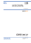
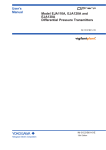
ST3000 Smart Multivariable Flow transmitter is
a differential pressure transmitter for mass flow
measurement for gas. It measures process DP,
SP, and temperature simultaneously and outputs
analog 4 to 20mA signal proportional to the
mass flow (volume flow at the standard
condition).
FEATURES
• Three process variable measurements and a
mass flow calculation with one transmitter.
• High accuracy and high range ability
Past instrumentation
Calculator
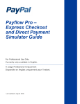
APPLICATIONS
Mass flow
(Compensated flow rate)
Measurement fluid
N2, O2, H2, Ar, Steam, Natural gas, Air, etc.
Applications
•
•
•
•
Gas
Differential pressure
transmitter
Pressure
transmitter
Temp.
sensor
Custody transfer of gas at chemical/steal market.
Flow control of fluid gas for an incinerator or a boiler.
Management of utility such as steam and air.
Flow rate measurement of H2 or other flamable gases at
hazardous area.
FUNCTIONAL SPECIFICATIONS
Instrumentation of model JTD720
Type of protection
JIS C 0920 watertight: NEMA 3 and 4X
JIS F 8001 class 2 watertight IEC IP67
JIS Flame-proof approval
Mass flow
(Compensated flow rate)
Exd IIB+H2 T4
Measuring span/Setting range/Working
pressure range
Gas
Model
JTD720A
See Table 1.
Temp.
sensor
Temperature input
RTD (Pt 100Ω or JPt 100Ω)
Output / Communication
Analog output (4 to 20 mA)
Digital output (DE protocol)
Specifications are subject to change without notice.
-1-
2nd Edition
No. SS2-DST100-0700
Azbil Corporation
PHYSICAL SPECIFICATIONS
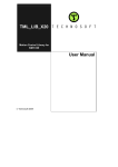
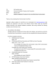
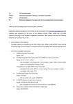
Power supply and load resistance
17 to 45V DC. A load resistance of 250Ω or more is
necessary between loops. (See Figure 2.)
Materials
Fill fluid
Ambient temperature
For general purpose (Silicone oil)
For oxygen service (Fluorine oil)
Normal operating range
-15 to 65°C (for general purpose models)
-10 to 65°C (for oxygen service models)
-15 to 65°C (digital indicator model)
Center body
SUS316
Operative limits
Transmitter case
-40 to 70°C (for general purpose models)
-40 to 70°C (for oxygen service models)
-30 to 70°C (digital indicator model)
For wetted parts
Aluminum alloy
Meter body cover
SCS14A (SUS316 equivalent)
JIS flame-proof model
-15 to 60°C (JIS flame-proof model)
Centerbody
SUS316 (Diaphragm SUS316L)
Temperature range of wetted parts
Vent plugs
SUS316
Normal operating range
-15 to 65°C (for general purpose models)
-10 to 65°C (for oxygen service models)
Gaskets
FEP
Operative limits
-40 to 70°C (for general purpose models)
-40 to 80°C (for oxygen service models)
-30 to 70°C (digital indicator model)
Bolts and nuts (for meterbody covers)
Carbon steel (SNB7), SUS304
Finish
JIS frame-proof model
-15 to 60°C (JIS flameproof model)
Housing
Light beige (Munsell 4Y7.2/1.3)
Ambient humidity
Cap
10 to 90% RH
Dark beige (Munsell 10YR4.7/0.5)
Stability against supply voltage change
Weight
±0.005% F.S./V
Approx. 4.4 kg
Lightning protection
Peak value of voltage: 100 kV
Peak value of current: 1000A
INSTALLATION
Dead time
Electrical connection
Approx. 0.4 sec.
G1/2 internal thread
Damping time
Grounding
Selectable from 0 to 32 sec. in ten stages
Resistance 100Ω max.
Output saturation point
Upper limit: 20.8 mA
lower limit: 3.8 mA
Mounting
Vibration characteristics
Process connection
Can be installed on a 2-inch horizontal or vertical pipe
(can be directly mounted on a process pipe).
Rc1/2, Rc1/4
Amplitude 1.5 mm / Frequency 0 to 9 Hz
Acceleration 5 m/S2 (0.5 G) / 9 to 60 Hz
-2-
Azbil Corporation
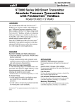
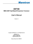
Differential
pressure
No. SS2-DST100-0700
DP
PP - PPELV.
PPREF
Static pressure PP
Temperature
PTREF
PT - PTELV.
DP - DPLRV.
DPSPAN
Output
PT
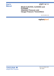
DP:
Differential pressure
DPLRV.: Value to output 0% (4 mA) of
differential pressure
DPSPAN: Span of differential pressure range
PP:
Static pressure (process pressure)
PPREF.: Designed process pressure
PPELV.: Elevation value of static pressure
PT:
PTREF.:
PTELV.:
Process temperature
Designed process temperature
Elevation value of temperature
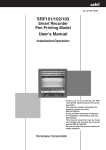
R = Supply voltage - 17.9
0.0218
Operative range
280
250
0
17
23.4 24
45
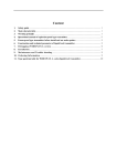
133.3
101.3
80
53
27
13
8.0
5.3
2.0
Unusable range
1.3
-40
Supply voltage E (V DC)
Normal operating
range
Operative limit
Load resistance R (Ω)
1243
Operative limit
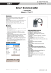
Working pressure P (kPa {mmHg} abs.)
Figure 1 Calculation equation
-18
40
50
60 65 70
80 85
Temperature of wetted parts ( C)
Figure 2 Supply voltage and load resistance
characteristics
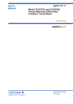
Figure 3 Working pressure and temperature of wetted parts
OPTIONAL SPECIFICATIONS
Material certificate
The material certificate shows the chemical composition,
heat-treatment conditions, and mechanical properties of
the materials used for the wetted parts.
Elbow
This is an adaptor for changing the electrical conduit
connection port from the horizontal to the vertical
direction, if required by wiring conditions in the field. One
or two elbows may be used as needed.
Strength calculation sheet
The strength calculation sheet indicates the strength of the
meter body cover, flanges, bolts and etc.
Water free treatment (including oil free
treatment)
Withstand pressure and air tight test (for
general purposes)
The transmitter is shipped with dry and oil-free wetted
parts.
The withstand pressure and air tight test result sheet shows
the results of a pressure resistance test (under water
pressure for 10 minutes) and a gas-tightness test (using N2
gas for 10 minutes) performed on the wetted parts.
Oil free treatment
The transmitter is shipped with oil-free wetted parts.
Test report
The test report indicates the results of appearance, I/O
characteristics, insulation resistance, and breakdown
voltage tests.
-3-
Azbil Corporation
No. SS2-DST100-0700
Transmitter handling notes
CAUTION
• After installing the transmitter, do not stand on it.
Using it as a foothold could cause it to collapse and
cause physical injury.
• Be careful not to hit the glass indicator with tools etc.
This could break the glass and cause injury.
• The transmitter is heavy. Wear safety shoes and take
care when installing it.
To make the most of the performance this transmitter can
offer, please use it properly noting the points mentioned
below. Before using it, please read the user’s manual.
Transmitter installation notes
WARNING
• When installing the transmitter, ensure that gaskets do
not protrude from connecting points into the process
(such as adapter flange connection points and
connecting pipes and flanges). Gasket protrusion may
result in leaks and output errors.
• Do not use the transmitter outside its defined pressure,
temperature, and connection specifications. A serious
accident may otherwise occur due to damage and leaks.
• When performing wiring work in explosion-proof
areas, follow the work method specified in the
explosion-proof guidelines. In addition, when the
wiring for an explosionproof product is a pull-in
pressure-resistant packing-cable, be sure to use a
pressure-resistant packing-cable adapter certified by
Yamatake Corporation.
• Be sure to use the cable which allowable temperature is
more than 65°C.
Wiring notes
WARNING
• To avoid shocks, do not perform electrical wiring work
with wet hands or with live wires.
CAUTION
• Do wiring work properly in conformance with the
specifications. Wiring mistakes may result in
malfunction or irreparable damage to the instrument.
• Use a power supply that conforms to the specifications.
Use of an improper power supply may result in
malfunction or irreparable damage to the instrument.
PERFORMANCE SPECIFICATIONS
Table 1 Performance specifications
DP Measuring span
DP setting range
0.75 to 100 kPa
-100 < URV < 100 kPa
-100 < LRV < 100 kPa
(*1)
(*2)
Note)*1: URV denotes the value for 100% (20 mA) output.
*2: LRV denotes the value for 0% (4 mA) output.
Design pressure setting range
Design temperature setting range
Calculation equation
Accuracy
(output after compensation)
0.17 to 3.5 MPa abs.
-100 to 650°C
See Figure 1.
Shown are the upper limit (URV) and lower limit (LRV) of the calibration range
or the percentage ratio of the maximum value of the span to χ (kPa.)
PPREF.: designed pressure
PPMAX.: max. pressure of process
Accuracy% = ± (0.025 + A + B + C + D + E) (* E: only when the temperature is input.)
PP REF⎞
- ≥ 12.5kPa
A: 0.075%................................................................... ⎛⎝ x × -----------PP MAX⎠
PP REF⎞
12.5 PP MAX- ≤ 12.5kPa
0.075% × ------------ × -----------% ................................... ⎛⎝ x × -----------PP REF
PP MAX⎠
x
PP MAX
PP MAX⎞
- %...................................................... ⎛ x × ------------ ≥ 25kPa
B: 0.1 × -----------⎝
3.5
PP REF⎠
PP MAX⎞
25 PP MAX- PP
MAX
- %.............................. ⎛ x × ------------ ≤ 25kPa
0.1 × ------ × -----------× -----------⎝
x PP REF 3.5
PP REF⎠
C: 0.075%................................................................... PP REF ≥ 0.35MPa abs.
0.35
0.075 × ------------- % ................................................... PP REF ≤ 0.35MPa abs.
PP REF
x
D: 0.15 × ------------------------------- %
PP REF × 1000
E: 0.1% (Only when the temperature is input.)
Square root output:
When output is 50 to 100%; same as that of linear output.
50
When output is 7.1 to 50%; value of linear output × ------------------- %
Output
(Not specified for dropout area)
When output is 7.1% or below;Not specified
-4-
No. SS2-DST100-0700
Azbil Corporation
Table 1 Performance specifications
Working pressure rating
Low flow cut-off
Working pressure range
Temperature effect
(after compensation)
3.5 MPa max. (For vacuum pressure, see Figure 3).
Value of cut-off: The output is changeable from 0 to 20%. – 100 ≤ URV ≤ 100 kPa
Drop-out type: Zero or linear output
3.5 MPa abs. max. (refer to Figure 3 for negative pressure.)
Shown are the upper limit (URV) and lower limit (LRV) of the setting range or the
percentage ratio of the maximum value of the span to χ (kPa.)
PPREF: designed pressure
PPMAX.: max. pressure of process
Zero shifts: ± 0.47% / 30°C change
(differential pressure 25 kPa, design pressure 0.5 MPa, process
pressure 0.6 MPa abs. max.)
Zero shift% / 30°C = ± (0.15 + A + B + D)
(* D: only when the temperature is input.)
12.5 PP MAXA: 0.16% × ------------ × -----------PP REF
x
25 PP MAX- PP
MAX
B: 0.1 × ------ × -----------× -----------3.5 PP REF
x
D: 0.2% (Only when the temperature is input.)
Total shifts: ±0.76% / 30°C change (included zero span shifts)
(differential pressure 25 kPa, design pressure 0.5 MPa, process
pressure 0.6 MPa abs. max.)
Zero shift% / 30°C change = ± (0.2 + A + B + D)
(* D: only when the temperature is input.)
Calibration accuracy
for differential pressure transmitter
PP REF⎞
- ≥ 12.5kPa
A: 0.24% .................................... ⎛⎝ x × -----------PP MAX⎠
PP REF⎞
12.5 PP MAX- ≤ 12.5kPa
%............ ⎛ x × -----------0.24 × ------------ × -----------⎝
PP REF
PP MAX⎠
x
PP MAX
PP REF⎞
- % ....................... ⎛ x × ------------ ≥ 25kPa
B: 0.1 × -----------⎝
3.5
PP MAX⎠
PP REF⎞
25 PP MAX- PP
MAX
- % . ⎛ x × ------------ ≤ 25kPa
0.1 × ------ × -----------× -----------⎝
PP MAX⎠
x PP REF 3.5
C: 0.1% .......................................... PP REF ≥ 0.35MPa abs.
0.35
0.1 × ------------- %.......................... PP REF ≤ 0.35MPa abs.
PP REF
D: 0.2% (Only when the temperature is input.)
Shown are the upper limit (URV) and lower limit (LRV) of the calibration range
or the percentage ratio of the maximum value of the span to χ (kPa.)
Linear output: ± 0.1% .......................................... χ ≥ 5kPa
5
± ⎛⎝ 0.025 + 0.075 × ---⎞⎠ %.................. χ ≤ 5kPa
χ
Calibration accuracy
for pressure transmitter
Shown are the upper limit (URV) and lower limit (LRV) of the calibration range
or the percentage ratio of the maximum value of the span to χ (kPa.)
Linear output: ± 0.1% .......................................... χ ≥ 0.35kPa abs.
0.35
± ⎛⎝ 0.025 + 0.075 × ------------⎞⎠ % ....... χ ≤ 0.35kPa abs.
χ
Calibration accuracy
for temperature transmitter
Temperature input type
– 100 ° C ≤ LRV , URV ≤ 650 ° C and span 50°C or more.
50 - + 0.05⎞ % F.S.
± ⎛⎝ 0.3 × -----------⎠
span
Resistance thermobulb Pt100Ω or JPt100Ω
-5-
Azbil Corporation
No. SS2-DST100-0700
MODEL SELECTIONS
JTD720A - I II III IV V - VI VII VIII IX X - Options
Measuring span
0.75 to 100 kPa
Basic model no. Selections
JTD720A -
Optional specifications Options
-
I Output /
4 to 20 mA
Communications
Digital output (DE protocol)
1
XX No options
3
A5 Long vent/drain plugs
II Material
Meterbody Vent / Wetted parts of
cover drain plugs center body
III Fill fluid
Regular type (Silicon oil)
1
For oxygen service (Fluorine oil) *1
2
IV Process
connection
Rc1/2, top connection
SCS14A
V Bolts / nuts
material
SUS316
SUS316
F1 Without temperature
compensation *2
G1 With one elbow
E
D1 Water free finish (with oil
free finish)
A
D2 Oil free finish
Rc1/2, bottom connection
B
T1 Test report
Rc1/2, front connection
D
T2 Material certificate (Mill
sheet)
Rc1/4, top connection
L
Rc1/4, top connection
L
Rc1/4, bottom connection
M
Rc1/4, front connection
P
T5 Strength calculation sheet
Carbon steel (SNB7)
1
SUS304
2
Option 1
VI Electrical
connection /
explosion-proof
T3 Document for high
pressure gas regulation
T6 Withstand pressure and air
tight test
-
G1/2, watertight
C7 Process connection; reverse
X
G1/2, JIS Flameproof with 1 pc. of cable gland attached 2
G1/2, JIS Flameproof with 2 pcs. of cable gland attached 3
VII Built-in
None
indicating smart
0 to 100% linear scales
meter
Engineering unit scales
X
1
2
VIII Finish
Standard
X
IX Fail safe
None
X
Upper limit of output at abnormal condition
U
Lower limit of output at abnormal condition
D
X Mounting bracket None
Note
X
Carbon steel
1
SUS304
2
For replacement
F
*1: Included oil-free finish.
*2: Code “F1” option must be selected when the temperature compensation is not needed.
-6-
Options
Selections
Azbil Corporation
No. SS2-DST100-0700
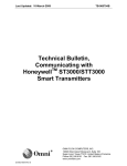
DIMENSIONS
Resistance
temperature
sensor
+
Receiver
- +
Power supply
24V DC
Process connection port
Process connection port
Terminal connection diagram
2-inch pipe
Digital meter
(optional)
Long vent
/drain plug
Terminal screw
for grounding
Electrical conduit
connection port
Electrical conduit connection port
Process connection port
(bottom parts)
Vertical installation
Digital meter
(optional)
M4 terminal screw
for grounding
Electrical conduit
connection point
Electrical conduit
connection point
Process connection
Process connection
Horizontal installation
-7-
2-inch pipe
1st Edition: Issued in July 2004
2nd Edition: Issued in Aug. 2012