1
Electrical network protection
Sepam
IEC 61850
communication
For Sepam series 20/40/80
User’s manual
10/2009
Safety instructions
Safety symbols and messages
Read these instructions carefully and look at the equipment to become familiar with
the device before trying to install, operate, service or maintain it. The following
special messages may appear throughout this bulletin or on the equipment to warn
of potential hazards or to call attention to information that clarifies or simplifies a
procedure.
Risk of electric shock
The addition of either symbol to a “Danger” or “Warning” safety label on a device
indicates that an electrical hazard exists, which will result in death or personal injury
if the instructions are not followed.
ANSI symbol.
IEC symbol.
Safety alert
This is the safety alert symbol. It is used to alert you to potential personal injury
hazards and prompt you to consult the manual. Obey all safety instructions that
follow this symbol in the manual to avoid possible injury or death.
Safety messages
DANGER
DANGER indicates an imminently hazardous situation which, if not avoided,
will result in death, serious injury or property damage.
WARNING
WARNING indicates a potentially hazardous situation which, if not avoided,
could result in death, serious injury or property damage.
CAUTION
CAUTION indicates a potentially hazardous situation which, if not avoided,
could result in minor or moderate injury or property damage.
CAUTION
CAUTION, used without the safety alerts symbol, indicates a potentially
hazardous situation which, if not avoided, could result in property damage.
Important notes
Restricted liability
Electrical equipment should be serviced and maintained only by qualified personnel.
No responsibility is assumed by Schneider Electric for any consequences arising out
of the use of this manual. This document is not intended as an instruction manual for
untrained persons.
Device operation
The user is responsible for checking that the rated characteristics of the device are
suitable for its application. The user is responsible for reading and following the
device’s operating and installation instructions before attempting to commission or
maintain it. Failure to follow these instructions can affect device operation and
constitute a hazard for people and property.
Protective grounding
The user is responsible for compliance with all the existing international and national
electrical codes concerning protective grounding of any device.
SEPED306024EN - 10/2009
IEC 61850
communication
SEPED306024EN - 10/2009
Contents
Presentation
2
Communication implementation steps
4
ECI850 Sepam server
Configuration
FTP server
Diagnostics pages
Commissioning and troubleshooting
5
5
13
14
18
ACE850 Communication interface
Configuration
FTP server
Web server
Commissioning and troubleshooting
20
20
24
25
31
Configuration of IEC 61850 protocol
Introduction
With SFT2841 setting and operating software
With SFT850 configuration software
34
34
36
43
Configuration of GOOSE communication
GOOSE configuration process
50
50
Conformance statements
ACSI conformance statement
MICS - Model implementation conformance statement
PICS - Protocol implementation conformance statement
PIXIT - Protocol implementation extra information for testing
TICS - Technical issues conformance statement
56
57
60
90
93
99
1
IEC 61850
communication
Presentation
General
IEC 61850 is a standard for communication networks and systems in substation.
Sepam units can be connected to an IEC 61850 station bus by one of the following
way:
b the ECI850 Sepam server, for Sepam series 20, Sepam series 40 and
Sepam series 80,
b the ACE850 communication interface, for Sepam series 40 and Sepam series 80
only.
Sepam units with ECI850 and ACE850 are compliant with:
b IEC 61850-6
b IEC 61850-7-1
b IEC 61850-7-2
b IEC 61850-7-3
b IEC 61850-7-4
b IEC 61850-8-1
Application and benefits
Based on the Ethernet protocol, the IEC 61850 communication standard ensures:
b high communication speeds and versatile communication architectures
b interoperability between manufacturers
With ECI850 Sepam server
The ECI850 Sepam server provides a high-performance, cost-effective, and versatile
solution for connecting Sepam units to an IEC 61850-compliant system.
This provides:
b compatibility with the whole Sepam range (series 20, 40 and 80) to fit your needs
perfectly,
b ability to upgrade existing Sepam units to ensure the durability of your assets,
b ability to connect up to 8 Sepam units to one ECI850, ensuring a cost-effective
solution,
b IEC 61850 logical nodes and configurable data sets to fit the needs of your Scada
system,
b high-performance because the ECI850 is not a generic gateway but a data server
dedicated to Sepam,
b up to 6 simultaneous IEC 61850 connections.
With ACE850 communication interface
The Sepam series 40 and Sepam series 80 fitted with the ACE850 communication
interface provide a built-in solution for demanding IEC 61850 applications:
b IEC 61850 logical nodes and configurable data sets to fit the needs of your Scada
system,
b Peer-to-peer communication capabilities on Sepam series 80 with GOOSE
messages to enhance your protection and control system without additional wiring,
b up to 6 simultaneous IEC 61850 connections.
Implementation
The Sepam IEC 61850 solution can be configured in two ways:
b The SFT2841 setting and operating software ensures straightforward configuration
and builds standard IEC 61850 configuration files.
b The SFT850 configuration tools adapt the communication profile of the devices to
the precise needs of the system.
The Sepam E-LAN runs in parallel with the IEC 61850 S-LAN, allowing Ethernet
connection of the SFT2841 setting and operating software to Sepam without any
extra cost.
The Sepam series 40 and Sepam series 80 fitted with the ACE850 communication
interface also support the Modbus TCP-IP communication protocol.
2
SEPED306024EN - 10/2009
Presentation
IEC 61850
communication
Typical architecture
b The ECI850 Sepam server can be connected to an Ethernet switch using
10/100BASE-T copper wire (radial connection).
b The Sepam series 40 and Sepam series 80 fitted with the ACE850 communication
interface can be connected to an Ethernet switch using:
v 10/100BASE-T copper wire (radial or ring connection)
v 100BASE-FX multi-mode fiber optic (radial or ring connection)
In order to optimize system performance, Schneider Electric recommends the
following:
b build a fault-tolerant backbone fiber-optic ring
b use IEC 61850 compatible managed switches
If Sepam units are connected in a ring configuration, the managed switches must be
compatible with RSTP 802.1d 2004 standard.
A global approach for building an Ethernet infrastructure can be found in the
"Transparent Factory Network Design and Cabling Guide" edited by Schneider
Electric.
DE80526
IEC 61850 architecture example
Control center
Maintenance
Local control
Fiber optic ring
RTU
E-LAN
S-LAN
Ethernet switch
P1/P2
ACE850
Sepam
series 80
P1/P2
ACE850
Sepam
series 40
P1/P2
P1/P2
ACE850
Sepam
series 80
ACE850
Sepam
series 40
Ethernet TCP/IP/IEC 61850
ECI850
ECI850
ECI850
RS 485/Modbus
Rc
ACE949-2
Sepam
series 80
Rc
Rc
ACE949-2
Rc
ACE949-2
Sepam
series 20
SEPED306024EN - 10/2009
Rc
ACE949-2
Sepam
series 20
Rc
ACE949-2
Sepam
series 20
Sepam
series 80
RS 485/Modbus
ACE949-2
Sepam
series 40
Sepam
series 40
ACE949-2
Rc
Rc
RS 485/Modbus
Rc
Sepam
series 40
ACE949-2
Sepam
series 20
ACE949-2
Rc
ACE949-2
Sepam
series 20
3
IEC 61850
communication
Communication implementation
steps
PE80319
IEC 61850 communication with the Sepam relays can be implemented using either
the ECI850 Sepam server, or the ACE850 communication interface (Sepam
series 40 or Sepam series 80 only).
Depending on the communication interface used, the following steps must be
performed.
ECI850 Sepam server configuration steps
ECI850: IEC 61850 Sepam server.
Configuration of Sepam Modbus interface
Communication between the ECI850 server and the Sepam is based on Modbus.
The first step deals with the configuration of the Sepam Modbus interface. It consists
of installing the Modbus interface in the equipment, wiring it to the RS 485 network
and configuring it, using the SFT2841 software.
Two kinds of communication interface can be used on Sepam:
b ACE949-2 for 2-wire RS 485 network
b ACE959 for 4-wire RS 485 network
Refer to the relevant Sepam user's and operation manual for details.
b Sepam series 20 user's manual, reference PCRED301005EN
b Sepam series 40 user's manual, reference PCRED301006EN
b Sepam series 80 operation manual, reference SEPED303003EN
b Sepam series 80 Modbus manual, reference SEPED303002EN
The physical layer parameters have to be configured, with the authorized values.
Remote control must be set in "direct" mode. With Sepam series 80, security features
must be disabled.
Parameters
Authorized values
Sepam address
1 to 247
Speed
19200 or 38400 bps
Parity
Even or odd
Configuration of the ECI850 server
The second step deals with the configuration of ECI850 Ethernet and Modbus layers.
See page 5.
ACE850 communication interface configuration steps
PB105301
ACE850 communication interface configuration involves configuring the ACE850
Ethernet layer. See page 20.
ECI850 Sepam server/ACE850 communication interface:
common configuration steps
These next 2 steps are common to both the ECI850 Sepam server and the ACE850
communication interface.
PB105300
ACE850TP communication interface.
Configuration of IEC 61850 protocol
The next step deals with the configuration of the IEC 61850 protocol. It generates a
CID file which contains the configuration of the communication data for all the Sepam
connected to an ECI850 Sepam server or an ACE850 communication interface.
b SFT2841software is used for standard configuration of IEC 61850 (see page 36).
All communication data is defined in standard ICD files that are gathered in a CID file
depending on the Sepam type.
b SFT850 software is used for advanced configuration of IEC 61850 (see page 43).
The configuration can be modified to optimize the exchange between devices:
v Suppress unused communication data
v Gather relevant communication data
v …
Transfer of the CID file to ECI850 or ACE850
The last step consists of loading the CID file, using the SFT2841 software, into either
the ECI850 Sepam server or the ACE850 communication interface.
The ECI850 and the ACE850 first perform a validation of the CID file before using it
for configuration. See page 49.
ACE850FO communication interface.
4
SEPED306024EN - 10/2009
ECI850 Sepam server
Configuration
IEC 61850
communication
Ethernet setup
Ethernet setup is required to enable access to the ECI850 over a network. If Ethernet
setup has already been done at installation time, proceed directly to the section:
Accessing the ECI850 over a network page 7.
Before configuring the ECI850, obtain a unique static IP address, subnet mask, and
default gateway address from the network administrator. Use a web browser or
Hyper Terminal to configure the ECI850 with the information obtained from the
network administrator, as described in the following sections.
Ethernet setup using Hyper Terminal
PE80058
1. Connect to ECI850 RS 232 port using the TCSEAK0100 Configuration kit or any
null modem cable.
2. Start Hyper Terminal (click Start > Run, then type hypertrm).
3. In the Name text box, type a name for the new connection (for example,
ECI config), then click OK.
4. In the Connect using drop-down list, select the computer COM port you will be
using, then click OK.
5. Set the COM properties as follows: Bits per second = 19200, Data bits = 8,
Parity = None, Stop bits = 1, and Flow control = None. Click OK.
6. Start the ECI850 Setup Utility:
b Cycle power or press the reset button on the ECI850 below the LED power status.
b While the green Power/Status LED blinks rapidly, press Enter on the computer
keyboard to access the setup utility.
Note: the Power/Status LED stops blinking after 5 seconds.
PE80619
7. The following screen should appear:
PE80059
Hyper Terminal: choose connection port.
Hyper Terminal: access ECI850 setup utility.
Hyper Terminal: configure serial port.
SEPED306024EN - 10/2009
5
IEC 61850
communication
ECI850 Sepam server
Configuration
ECI850 setup options
Option
1
2
3
4
5
6
Description
Setting
Used to select the language for the current
Hyper Terminal session.
Used to enter the static IP address of the
ECI850.
Used to enter the subnet mask of the network.
English, French, Spanish
Default: English
0.0.0.0 to 255.255.255.255
Default: 169.254.0.10
0.0.0.0 to 255.255.255.255
Default: 255.255.0.0
0.0.0.0 to 255.255.255.255
Default: 0.0.0.0
Used to enter the default gateway (router) IP
address used for wide area network (WAN)
communications.
Used to define the physical Ethernet
connection.
Saves the settings and exits the setup utility.
b 10T/100Tx Auto
b 10BaseT-HDo 10BaseT-FD
b 100BaseTx-HD
b 100BaseTx-FD
Default: 10T/100Tx Auto
-
Ethernet setup using a web browser
1. Disconnect your computer from your network.
Note: after disconnecting from your network, your computer should automatically use the default
IP address 169.254.###.### (### = 0 to 255) and the default subnet mask 255.255.0.0. If the IP
address is not automatically configured, contact your network administrator to set up a static IP
address.
2. Connect an Ethernet crossover cable (available in the kit TCSEAK0100) from the
ECI850 to the computer.
3. Start Internet Explorer (version 6.0 or higher).
4. In the Address text box, type 169.254.0.10, then press Enter. Type
Administrator for your Username, type ECI850 for your Password, then click
OK. Usernames and Passwords are case sensitive.
5. Set up parameters as described in the ”Ethernet and TCP/IP settings” section on
page 8.
6. Reconnect your computer to your network. If you assigned a static IP address to
your computer in step 1, you must restore your computer's original settings before
reconnecting to your network.
6
SEPED306024EN - 10/2009
IEC 61850
communication
ECI850 Sepam server
Configuration
Accessing the ECI850 over a network
After setting up the Ethernet parameters, the user can access the ECI850 over an
Ethernet LAN using Internet Explorer 6.0 or higher.
PE80627
Logging into the ECI850
Action
Result
1. Launch Internet Explorer 6.0 or higher.
2. In the Address text box, type the address of
your ECI850 (169.254.0.10 is the default), then
press Enter.
3. Type your Username (Administrator is the
default) and Password (ECI850 is the default) into
the text boxes, then click OK.
4. Click Setup to access the ECI850 setup page,
or click Diagnostics to access the ECI850
diagnostics page.
Opens Internet Explorer.
Opens the Login dialog box.
Enters the Username and Password, then
opens the ECI850 home page.
Opens the Setup or Diagnostics pages.
Logging Out
We recommend logging out whenever you do not need access to the ECI850. To log
out of the ECI850 configuration session, click Log Out to end your session.
ECI850 home page.
ECI850 user interface overview
The ECI850 ships with several pre-installed web pages used for ECI850 setup,
configuration and diagnostics. See Table below for a description of each web page.
Access to pages can be restricted (see Web Pages Access).
ECI850 Web Page Description
Setup
Ethernet & TCP/IP
Serial Port
IP Filtering
SNMP Parameters
SNTP Parameters
User Accounts (1)
Web Page Access (1)
Diagnostics
Communication
statistics
ECI850 Summary
Configure Ethernet and TCP/IP communication settings.
Set up or change serial communication parameters.
Set up which IP addresses can access the ECI850.
Enable and configure the Simple Network Management
Protocol (SNMP), which allows the ECI850 to identify itself to
network devices requesting SNMP data.
Enable and configure the Simple Network Time Protocol
(SNTP), which allows the ECI850 to be time synchronized.
Create and edit groups and users.
Select web page access rights for each user group.
See
page 8
page 9
page 10
page 11
page 12
page 9
page 10
Displays diagnostic data used to troubleshoot network
page 14
problems.
This page contains information about your specific ECI850, page 16
including the serial number, manufacturing date and Media
Access Control (MAC) address.
Read Device Registers Allows ECI850 administrators to read register data from a page 17
serial device connected to the ECI850.
(1) Accessible by administrators only.
SEPED306024EN - 10/2009
7
IEC 61850
communication
ECI850 Sepam server
Configuration
Communications setup
PE80612
Ethernet and TCP/IP settings
Procedure
Action
Result
1. From the Setup page, click Ethernet &
TCP/IP.
2. Select your media type. Contact your network
administrator if you do not know.
3. Enter your IP address, subnet mask, and
default gateway address assigned to your
ECI850 by your network administrator.
4. Click Apply.
Opens the Ethernet & TCP/IP page.
Selects the media type.
Enters the Ethernet parameters for the
ECI850.
Note: if you enter an IP address that is used by
another device, you will be prompted to select
a new IP address. See "Duplicate IP address
detection" below.
Updates the ECI850 Ethernet and TCP/IP
settings.
Note: after making changes to the Ethernet parameters and clicking Apply, the ECI850 will
reboot.
ECI850 Ethernet & TCP/IP page.
Description of Ethernet and TCP/IP settings
Option
Description
Media Type
IP Address
Used to define the physical Ethernet
connection or media type.
Used to enter the static IP address of
the ECI850.
Subnet Mask
Used to enter the Ethernet IP subnet
mask address of your network.
Default Gateway
Used to enter the gateway (router) IP
address used for wide area network
(WAN) communications.
Allow CID file to
Check this box if you want the IP
override IP parameters parameters contained in the CID file to
replace the above configuration.
Keepalive
Timeout value used to test for session
disconnection.
FTP session inactivity Timeout value used to force
timeout
disconnection of an inactive FTP
session
Setting
b 10T/100Tx Auto
b 10BaseT-HD
b 10BaseT-FD
b 100BaseTX-HD
b 100BaseTX-FD
Default: 10T/100Tx Auto
0.0.0.0 to 255.255.255.255
Default: 169.254.0.10
0.0.0.0 to 255.255.255.255
Default: 255.255.0.0
0.0.0.0 to 255.255.255.255
Default: 0.0.0.0
Default: not checked
1 to 60 seconds
Default: 30 seconds
30 to 900 seconds
Default: 30 seconds
Duplicate IP address detection
While connected to your network, the ECI850 publishes its IP address. The IP
address of the ECI850 must be unique on the network it is connected to. If it is not
unique the Power/Status LED repeats a four blink-pause pattern. Assign a new IP
address to the ECI850 or to the conflicting device.
8
SEPED306024EN - 10/2009
IEC 61850
communication
ECI850 Sepam server
Configuration
PE80611
Serial port configuration
Procedure
Action
Result
1. From the Setup page, click Serial Port.
Opens the Serial Port page.
2. Select your physical interface, baud rate,
Selects the serial port options.
parity, and response timeout (see Table below).
3. Click Apply.
Updates the ECI850 Serial Port settings.
ECI850 Serial Port page.
Description of serial port settings
Option
Description
Setting
Physical Interface
Used to select how the ECI850 serial RS 485 4-wire, RS 485 2-wire
port is physically wired.
Default: RS 485 2-wire
Baud Rate
Used to select the data transmission
19200, 38400
Default: 38400
speed over the serial connection.
Parity
Used to select which parity bit is used Even, Odd
for checking data.
Default: Even
Response Timeout
Used to select how long the ECI850
0.1 to 2 seconds
will wait to receive a response from a Default: 0.3 second
device. Default value should usually be
kept.
Note: the settings defined here must match the settings of the connected Sepam devices.
Access control configuration
PE80617
User accounts
ECI850 users are assigned Usernames and Passwords. Each user belongs to a
group, and each group has access rights to the ECI850 web pages assigned by the
ECI850 administrator.
Note: there are two default user accounts: Administrator (password is ECI850) and Guest
(password is Guest).
Procedure
Action
Result
1. From the Setup page, click User Accounts. Opens the User Accounts page.
ECI850 User Accounts page.
2. If you want to change a group name, type a Enters a new group name.
new name in one of the Group text boxes (the
Administrator group name cannot be changed).
3. In the Users section, enter a Name (1 to 24 Enters the name and password for a user.
characters) and Password (0 to 12 characters)
for a new user.
Note: Usernames and Passwords are casesensitive and can contain only alphanumeric
characters.
4. Select a group and the default language for Selects the group and language for a user.
the new user.
5. Repeat steps 3 and 4 for each additional user Continues adding users.
you want to add.
6. Click Apply.
Saves all of the user account settings.
ECI850 accounts and passwords description
Account
Default Password
SEPED306024EN - 10/2009
Administrator (default account)
ECI850
Guest (default account)
Guest
User-defined accounts (up to 11 accounts
possible)
No default — Password is user-defined
9
IEC 61850
communication
ECI850 Sepam server
Configuration
PE80618
Web page access
Procedure
Action
ECI850 Web Page Access page.
Result
1. From the Setup page, click Web Page
Access.
2. In the Communication statistics row, select
the access level (None, Read-only, or Full)
that each user group will have for the Ethernet
& TCP/IP web page.
3. To allow Guest access to the web page,
select Read-only under the Guest column. if
the Guest group is Read-only, other groups can
only be set to Read-only or Full.
4. Repeat steps 2 and 3 for the other rows.
Opens the Web Page Access page.
5. Click Apply.
Saves the page access settings.
Group access
Group
Access
Administrator
Guest
Three user-defined groups
See Table below for an explanation of access
levels for each group.
Allows the default Guest group to access the
web page.
Selects the access level for each web page.
Full access to all web pages.
We recommend that you change the default
administrator password for system security the
first time you log in.
Read-only access to selected web pages.
Choosing from the following options, the
administrator assigns web page access for
each group. Access levels are as follows:
b None: a group has no access to selected
web page
b Read-only: password grants a group readonly access to the selected web page
b Full: a group has the same access as the
Administrator group to the selected web page
PE80613
IP address filtering
This function allows the administrator to specify which IEC 61850 clients and
SFT2841 have access to the ECI850 services.
Note: if IP addresses filtering is enabled, access is forbidden to any device not in the filtered list.
Procedure
Action
Result
1. From the Setup page, click TCP/IP Filtering. Opens the TCP/IP Filtering page.
2. Check Enable Filtering.
Activates filtering.
3. In the IP address column, enter the TCP/IP
client address
Enters an IP address for a TCP/IP client that
will have access to the IEC 61850 server or to
the SFT2841 link or both.
4. In the IEC 61850 and SFT2841 link columns, Selects the access level for the corresponding
check what applies.
IP address. SFT2841 link, IEC 61850 or both.
ECI850 TCP/IP Filtering page.
5. Repeat steps 3 and 4 to add more IP
addresses.
6. Click Apply.
10
Continues adding IP addresses for filtering.
Saves the IP address filtering list.
SEPED306024EN - 10/2009
IEC 61850
communication
ECI850 Sepam server
Configuration
Configuring additional features
PE80616
SNMP parameters
The ECI850 supports SNMP, allowing a network administrator to remotely access it
with an SNMP manager and view the networking status and diagnostics in the MIB2
format.
Procedure
Action
Result
1. From the Setup page, click SNMP
Parameters.
Opens the SNMP Parameters page.
2. Check ENABLE SNMP to turn ON the simple Activates SNMP.
network management protocol.
ECI850 SNMP Parameters page.
Note: if you uncheck Enable SNMP and click
Apply, the ECI850 will reboot and SNMP
functionality will be turned OFF.
3. Enter the system contact, system name,
system location, read-only community
name, and the read-write community name.
4. Click Apply.
Settings description
Option
Description
Enable SNMP
System Contact
System Name
System Location
Read-only
Community Name
Read-write
Community Name
SEPED306024EN - 10/2009
Enters the SNMP system information and
community access names.
Saves the SNMP settings.
Setting
Checking the check box enables SNMP Default: not enabled
and MIB II support
Name of the administrative contact.
String (< 50 characters)
Default: empty string
Name given to the ECI850 and Sepam String (< 50 characters)
Default: empty string
subnet.
Location of the ECI850.
String (< 50 characters)
Default: empty string
SNMP community that has read-only
String (< 50 characters)
access to the MIB. Acts as a password. Default: "public"
SNMP community that has read-write
String (< 50 characters)
access to the MIB. Acts as a password. Default: "private"
11
IEC 61850
communication
ECI850 Sepam server
Configuration
PE80626
SNTP parameters
SNTP is the time synchronization method required by IEC 61850. It is used in mode
3-4 (unicast mode).
The ECI850 supports SNTP to enable synchronization between the ECI850 and
Sepam devices.
b If SNTP is not turned ON, time synchronization must be provided to the Sepam
devices by other means (ECI850 time is meaningless in that case).
b If SNTP is turned ON, time synchronization must be set up on Sepam, to the
communication channel linked to ECI850 (there are 2 communication channels on
Sepam series 80).
Procedure
Action
ECI850 SNTP Parameters page.
Result
1. From the Setup page, click SNTP
Parameters.
2. Check Enable SNTP to turn ON the simple
network time protocol.
Opens the SNTP Parameters page.
3. Enter the time offset from UTC of your
location.
4. Check Enable DST to turn ON the Daylight
Saving Time (summer Time) feature.
5. Enter the time offset for Daylight Saving Time
and the start and end time.
Enters the time zone.
Activates SNTP.
Activates Daylight Saving Time.
Enters DST time offset: start time and end
time.
6. Enter the IP address of the primary (or only) Enters the address of the SNTP server(s).
SNTP server. If available, enter the IP address
of a secondary server to be used if the primary
one is not responding.
7. Enter the poll interval between two requests Enters poll interval
to the server.
8. Click Apply.
Saves the SNTP settings.
Setting descriptions
Option
Enable SNTP
Time Zone Offset
Enable Daylight
Saving Time
DST offset
DST starts
DST ends
Primary Server IP
Address
Secondary Server IP
Address
Poll Interval
12
Description
Setting
Enables the time and date of the ECI850
to be set by the Simple Network Time
Protocol (SNTP) server.
Determines the difference between local
time and Coordinated Universal Time
UTC (same as GMT).
Enables the use of Daylight Saving Time
(Summer time).
Difference between standard time and
Daylight Saving Time.
If enabled, DST starts on the selected
date.
If enabled, DST ends on the selected
date.
The IP address of the SNTP server the
ECI850 contacts to get the time
message.
The IP address of another SNTP server
the ECI850 contacts in case the primary
server is down.
Controls how often the ECI850 contacts
the SNTP server for the correct time.
Default: not enabled
UTC-12 to UTC+14
Default: UTC
Default: not enabled
+ 30 or + 60 minutes
Default: + 60 minutes
Default: last sunday of March
Default: last sunday of
October
0.0.0.0 to 255.255.255.255
Default: 0.0.0.0
0.0.0.0 to 255.255.255.255
Default: 0.0.0.0
1 to 300 minutes
Default: 60 minutes
SEPED306024EN - 10/2009
IEC 61850
communication
ECI850 Sepam server
FTP server
PE80106
After you set up the Ethernet parameters, you can access the ECI850 FTP server,
using Internet Explorer or another FTP client. The following description is made using
Internet Explorer 6.
Note: this server features only a limited implementation of the FTP protocol and is therefore not
guaranteed to work with every client.
Logging into the FTP server
Action
Logging into the FTP server.
1. Launch Internet Explorer, type ftp:// and the IP
address of the ECI850 in the Address text box (for
example, ftp://10.10.10.10), then press Enter.
2. Type the Username and the Password in the text
boxes, then click Log On.
Result
Opens the Log On As dialog box.
Opens an FTP session with the ECI850
and displays the root directory of the
ECI850.
Note: access to the FTP server is restricted to accounts belonging to the Administrators group.
ECI850 directories
PE80625
Root directory
ECI850 directories view.
The root directory contains:
b the logical devices directory LD
It is structured as described by the IEC 61850 standard. There is one directory for
each Sepam Logical Device. In each of these, a COMTRADE directory contains the
disturbance files CFG and DAT These files can only be read. They can also be read
using IEC 61850 file transfer.
b the backup directory BAK
It contains the backup IEC 61850 file, if any. This file can only be read. This file is only
kept as an archive. It is not used by the ECI850.
b the ECI850 standard configuration file "ecicfg.txt". This file can be read or written.
It is checksum protected and must not be modified externally. When written to the
ECI850, it updates the device parameters except the Ethernet settings.
b the IEC 61850 configuration file CID (if loaded). This file can be read or written. Its
content is protected and can be modified only with the SFT2841 or SFT850 tools.
Transferring files from the ECI850 to the computer
Action
1. Right-click the file you want to download from the
ECI850, then click Copy.
2. Locate the folder you want to save the copied file,
right-click in the folder's window, then click Paste.
3. Repeat steps 1 and 2 if you want to copy other files
from the ECI850
4. Click the Close button on the Internet Explorer
window.
Result
Copies the selected file.
Pastes the file into the folder.
Continues to copy files from the ECI850.
Closes Internet Explorer and ends the
FTP connection to the ECI850.
Transferring files from the computer to the ECI850
Write-able files are transferred to the ECI850 as described above, inverting source
and destination folders.
IEC 61850 configuration files can also be transferred with the SFT2841 software (see
page 40).
SEPED306024EN - 10/2009
13
IEC 61850
communication
ECI850 Sepam server
Diagnostics pages
Introduction
Diagnostics pages provide useful information for network monitoring, tuning, and
troubleshooting.
There are 3 diagnostics pages:
b Communication statistics page to troubleshoot Ethernet TCP/IP communication
b ECI850 summary page to display information about the ECI850 Sepam server
b Read device registers page to troubleshoot Modbus communication
PE80614
Communication statistics
Procedure
Action
Result
1. From the Diagnostics page, click
Communication Statistics.
2. View the data
Opens the Communication Statistics page.
3. Click Reset.
Resets the ECI850 cumulative diagnostic data to 0.
See “Interpreting Statistics” below.
Interpreting statistics
Statistic
Description
Ethernet
Link Status
Frames Transmitted OK
Collisions
Excessive Collisions
Frames Received OK
CRC Errors
Alignment Errors
ECI850 Communication Statistics page.
Frames Too Long
Frames Too Short
A status string that represents the speed and duplex
setting being used to communicate with the linking
partner.
A counter that increments each time a frame is
successfully transmitted.
A counter that increments each time a frame is
retransmitted due to collision detection.
A counter that increments each time a frame is not able
to be sent due to reaching the maximum collision status
based on the Truncated Binary Exponential Backoff
algorithm.
A counter that increments each time a frame is
successfully received.
A counter that increments each time a frame is received
that has a checksum/CRC that does not match what is
calculated.
A counter that increments each time a frame is received
that has a checksum/CRC error and does not end on an
8-bit frame boundary.
A counter that increments each time a frame is received
that is larger than the allowed maximum size defined in
the standards (frames larger than 1518 bytes).
A counter that increments each time a frame is received
that is smaller than the allowed minimum size defined in
the standards (frames smaller than 64 bytes).
SFT2841 link
Frames Sent
A counter that increments each time a frame is sent.
Frames Received
A counter that increments each time a frame is received.
Protocol Errors
A counter that increments each time an ill-formed
message is received.
A status value that represents the number of
connections that are active at the moment the
diagnostics page is refreshed. A maximum of 4
connections are supported. Clicking Active Connections
opens a new window with a list of all of the active client
connections.
A counter that increments each time a connection is
made to the ECI850.
A status value that represents the maximum number of
connections that were active at any given moment.
A counter that increments each time a read request
message is received.
A counter that increments each time a write request
message is received.
A counter that increments each time a reply message is
sent.
Active Connections
Accumulative Connections
Maximum Connections
Inbound Read Messages
Inbound Write Messages
Outbound Reply Messages
14
SEPED306024EN - 10/2009
IEC 61850
communication
ECI850 Sepam server
Diagnostics pages
Interpreting statistics (cont.)
Statistic
Description
IEC 61850
Protocol Errors
Active Connections
Accumulative Connections
Server indications
Variable Reads
Variable Writes
Information reports
A counter that increments each time a received request is
incorrect or cannot be satisfied.
A status value that represents the number of connections
that are active at the moment the diagnostics page is
refreshed. A maximum of 6 connections are supported.
Clicking Active Connections opens a new window with a
list of all of the active client connections.
A counter that increments each time a connection is made
to the ECI850.
A counter that increments each time the server receives
a protocol indication.
A counter that increments each time the server receives
a read variable request.
A counter that increments each time the server receives
a write variable request.
A counter that increments each time the server sends an
information report message.
Serial port
Frames Sent
A counter that increments each time a frame is sent.
Frames Received
A counter that increments each time a frame is received.
CRC Errors
A counter that increments each time a message is
received that has a CRC that does not match what is
calculated. Typically the result of wiring issues.
A counter that increments each time an ill-formed
message is received.
A counter that increments each time a request message
is sent without receiving a corresponding response
message within the allowed time. Timeouts are typically
the result of configuration errors or a non-responsive
device.
A counter that increments each time a read request
message is sent.
A counter that increments each time a write request
message is sent.
Protocol Errors
Timeouts
Outbound Read Messages
Outbound Write Messages
SEPED306024EN - 10/2009
15
IEC 61850
communication
ECI850 Sepam server
Diagnostics pages
PE80620
ECI850 Summary
Procedure
Action
Result
1. From the Diagnostics page, click Opens the ECI850 Summary page.
ECI850 Summary.
2. View the data
See “Interpreting information” below.
Interpreting information
Information
Description
Device Information
ECI850 Summary page.
Firmware Version
The firmware version that is installed on the ECI850
System Idle Time
MAC Address
A percentage from 0% to 100% indicating the average
processor time that is not being used
The unique Ethernet hardware address of the ECI850
Serial Number
The serial number of the ECI850
Model Number
The ECI850 model number
Hardware Version
The ECI850 hardware version
Manufacture Date
The date the ECI850 was manufactured
IEC 61850 Device Name
The name given to the ECI850 device in the IEC 61850
configuration file
IEC 61850 Configuration files
File
Name
"Current" is the last loaded CID file
"Backup" is the archived CID file
Name of the file as defined at loading
Edit time
Time at which the configuration file has been created
Version
Version of the file as defined in the file header
Revision
Revision of the file as defined in the file header
Restore
This button overwrites the content of the current file with
the content of the backup file.
IEC 61850 Logical devices
Name
Name of the logical device built from the configuration file
Label
Label of the device (Sepam label or ECI850 system
name)
Type of the device as declared in the configuration file
Type
Address
Status
Modbus address of the device as declared in the
configuration file
b Offline: the declared device does not respond to
ECI850 requests
b Wrong type: the device at this address is not of the
expected type
b Init: the device database is being initialized
b Online: the device is operational
b Bad Conf.: there is an error in the configuration file, the
device is ignored
Date and time
16
Last Successful Time
Synchronization (UTC)
ECI850 Date and Time (UTC)
Displays the last time the ECI850 successfully contacted
the SNTP server (UTC time).
Current time and date of the ECI850 (UTC time).
ECI850 Date and Time (local)
Current time and date of the ECI850 (local time).
SEPED306024EN - 10/2009
IEC 61850
communication
ECI850 Sepam server
Diagnostics pages
PE80615
Read Device Registers
Read Device Registers page can be used to check Modbus communication
between the ECI850 and Sepam devices.
Procedure
Action
ECI850 Read Device Registers page.
Result
1. From the Diagnostics page, click Read Device
Registers.
2. Enter the Device ID, Starting Register number, and
the Number of Registers to read.
3. Click Read Holding Registers or Read Input
Registers.
4. To change how the data is displayed in the Value
column, select Decimal, Hexadecimal, Binary, or
ASCII.
Opens the Read Device Registers page.
Enters the values to begin reading
registers for the specified device.
Displays the values for the listed
registers.
Selects how the data values are
displayed.
ECI850 Read Device Register Settings
Option
Description
Default
1
Starting Register
The address of the device that registers are
read.
The first register to read.
Number of Registers
The number of registers to read (1 to 10).
10
Register column
Lists the register numbers.
-
Value column
Lists the data stored in a register.
-
Decimal, Hexadecimal,
Binary, or ASCII options
Select an option to specify how the Value
column data is displayed.
Decimal
Device ID
SEPED306024EN - 10/2009
1000
17
ECI850 Sepam server
Commissioning and troubleshooting
IEC 61850
communication
PE80319
Installation and operating instructions
The ECI850 Sepam server must be installed and connected in accordance with the
instructions in the following documents:
b ECI850 installation guide (delivered with each ECI850),
reference 63230-216-314,
b Sepam series 20 user’s manual, reference PCRED301005EN,
b Sepam series 40 user’s manual, reference PCRED301006EN,
b Sepam series 80 operation manual, reference SEPED303003EN.
To download these documents, follow the procedure below:
1. Go to www.schneider-electric.com.
2. Type Sepam in the Search field.
3. Click Sepam series xx.
4. Click Download.
5. Click Technical Publications.
6. Click the manual you want to download.
ECI850: IEC 61850 Sepam server.
Troubleshooting
Troubleshooting makes use of:
b ECI850 front panel LED indicators
b ECI850 web diagnostics pages
It should be done in the following order:
1. Check the ECI850 connection to Ethernet.
2. Check the Modbus subnetwork.
3. Check the IEC 61850 configuration.
Serial status LEDs (yellow):
5 RX LED flashing: receiving data
6 TX LED flashing: transmitting data
7 RS 485 link mode:
b On: RS 485 mode
b Off: RS 232 mode
DE80346
ECI850 front panel LED indicators
Ethernet status LEDs (green):
1 LK LED on: Ethernet link active
2 TX LED flashing: transmitting data
3 RX LED flashing: receiving data
4 100 LED
b On: 100 Mb link speed
b Off: 10 Mb link speed
1
2
3
4
RS485
TX
LK
TX
RX
100
RX
ECI850MG
5
6
7
8
9
8 Reset button
9 Power/status LED
18
SEPED306024EN - 10/2009
IEC 61850
communication
ECI850 Sepam server
Commissioning and troubleshooting
ECI850 and Ethernet troubleshooting
Symptoms
Power/Status LED off
Ethernet LK LED off
Power/Status LED repeats
a four blink-pause pattern.
Possible cause
Action/Remedy
Source power is not applied or is not stable.
LED is burned out.
Proper link is not established.
Apply power or check source.
Check to see if other LEDs operate properly.
1. Make sure the proper cable is used and connected.
2. Make sure the proper media type is selected in the ECI850.
3. Check the communications setup configuration.
The IP address that the ECI850 was assigned is being used by Assign a new IP address to the ECI850 or to the conflicting device.
another network device.
Note: when a duplicate IP address is detected, the ECI850 resets its
specified IP address to the default IP address. When the ECI850
detects the conflict no longer exists, it will use the specified IP
address.
1. Verify all IP parameters are correct.
2. Verify ECI850 receives requests:
ping ECI850 by:
b going to DOS prompt
b typing ping and the ECI850 IP address, e.g.:
ping 169.254.0.10.
3. Verify that all browser internet connections settings are correct.
Cannot browse the ECI850. Incorrect network configuration.
Modbus subnetwork troubleshooting
Symptoms
RS 485 LED off
Serial TX not flashing
Serial TX flashing
Serial RX not flashing
Possible cause
Action/Remedy
ECI850 has not started correctly.
The IEC 61850 server is not configured and there is no
SFT2841 remote connection active.
The IEC 61850 server is not configured and there a SFT2841
remote connection active.
The IEC 61850 server is configured and there is no SFT2841
remote connection active.
Setting of ECI850 serial port does not match setting of Sepam
devices.
Modbus addresses configured in the IEC 61850 file or in the
SFT2841 do no match Sepam addresses.
The RS 485 network is not wired properly.
Check to see if there is an Ethernet connection problem.
This is a normal situation.
The SFT connection can be active on another ECI850. Check IP
addresses.
Check the IEC 61850 configuration file.
Check and correct settings.
Check and correct addresses.
Check and correct wiring.
IEC 61850 configuration troubleshooting
Symptoms
Possible cause
Action/Remedy
IEC 61850 clients can not
connect to the ECI850
Ethernet setup is not correct.
See above.
The maximum number of active connections is reached.
Check the active clients.
IEC 61850 clients connect The IEC 61850 server is not configured or the configuration file Download a valid configuration file.
to the ECI850, but no data is is not valid.
available
The IEC 61850 server is
The actual Sepam type at a given address is not the type
Check device address, correct the configuration file or replace
expected in the configuration file.
device.
working, but some logical
devices do not report data. The device is not communicating.
Check device, check its communication parameters, check wiring.
SEPED306024EN - 10/2009
19
IEC 61850
communication
ACE850 Communication interface
Configuration
Access to configuration parameters
PE80394
Configuring an ACE850 involves:
b configuring the standard Ethernet parameters (mandatory)
b configuring one or more of the following sets of advanced optional parameters:
v SNMP: Ethernet network management
v SNTP: time synchronization
v IP filtering: access control
v RSTP: Ethernet ring management
v User accounts: access control.
SFT2841: Sepam series 80 configuration screen.
The configuration parameters can be accessed from the Communication
configuration window in the SFT2841 software.
To access this window:
b For Sepam series 80:
v open the Sepam configuration window in SFT2841
v select the Ethernet communication port
v click on the relevant button
: the Communication configuration window
appears
v select the type of interface used: ACE850TP or ACE850FO.
PE80469
b For Sepam series 40:
v open the Sepam hardware configuration window in SFT2841
v check the "ACExxx Communication interface" box
v click on the relevant button
: the Communication configuration window
appears
v select the type of interface used: ACE850TP or ACE850FO.
SFT2841: Sepam series 40 configuration screen.
Ethernet and TCP/IP configuration
PE80395
Before configuring the ACE850, obtain a unique static IP address, subnet mask, and
default gateway address from the network administrator. See page 23.
Parameters
Description
Authorized values
Frame format
Media type
IP address
Subnet mask
Default gateway
SFT2841: Ethernet configuration.
Allow CID file to
override IP
parameters
Keep alive
FTP session
inactivity timeout
Used to select the format for data sent over
an Ethernet connection.
Used to define the physical Ethernet
connection.
Ethernet II, 802.3, Auto
Default: Ethernet II
ACE850TP
b 10T/100Tx Auto
b 10BaseT-HD
b 10BaseT-FD
b 100BaseTX-HD
b 100BaseTX-FD
Default: 10T/100Tx Auto
ACE850FO
b 100BaseFX-HD
b 100BaseFX-FD
Default: 100BaseFX-FD
Used to enter the static IP address of the 0.0.0.0 to 255.255.255.255
Default: 169.254.0.10
ACE850.
Used to enter the subnet mask of your
0.0.0.0 to 255.255.255.255
Default: 255.255.0.0
network.
Used to enter the default gateway (router) 0.0.0.0 to 255.255.255.255
Default: 0.0.0.0
IP address used for wide area network
(WAN) communications.
This parameter is not used for Modbus
Default: not checked
only communication.
Timeout value used to test for session
disconnection.
Timeout value used to force disconnection
of an inactive FTP session
1 to 60 seconds
Default: 30 seconds
30 to 900 seconds
Default: 30 seconds
Duplicate IP address detection
The ACE850 IP address must be unique in the network. If it is not unique, the Status
LED repeats a four blink-pause pattern and a new IP address must be assigned to
the ACE850 or to the conflicting device.
20
SEPED306024EN - 10/2009
IEC 61850
communication
ACE850 Communication interface
Configuration
SNMP configuration
PE80396
The ACE850 supports SNMP V1, allowing a network administrator to remotely
access it with an SNMP manager and view the network status and diagnostics in
the MIB2 format (only a subset of MIB2 is implemented).
Additionally, the ACE850 may be configured to send SNMP traps in the following
cases:
b ACE850 start/restart
b Link up
b Link down
b Authentication failure.
Parameters
System Name
System Contact
SFT2841: SNMP configuration.
System Location
Read-only
Community Name
Read-write
Community Name
Enable traps
Traps
Community Name
Manager 1 IP
address
Manager 2 IP
address
Description
Authorized values
This parameter is the same as the Sepam Not modifiable from this
label.
screen.
Name of the administrative contact
String (< 16 characters)
Default: empty string
Location of the Sepam/ACE850
String (< 16 characters)
Default: empty string
SNMP community that has read-only
String (< 16 characters)
access to the MIB. Acts as a password
Default: "public"
SNMP community that has read-write
String (< 16 characters)
access to the MIB. Acts as a password
Default: "private"
Checking this check box enables SNMP to Default: "not checked"
send traps.
SNMP community that is used with traps String (< 16 characters)
Default: "public"
IP address of the SNMP manager to which 0.0.0.0 to 255.255.255.255
Default: 0.0.0.0
traps are sent
IP address of a second SNMP manager to 0.0.0.0 to 255.255.255.255
Default: 0.0.0.0
which traps are sent
SNTP configuration
PE80397
SNTP is a time synchronization protocol that can be used to synchronize the
Sepam. SNTP is used in mode 3-4 (unicast mode).
b If SNTP is used, the synchronization source for Sepam must be defined as
Ethernet.
b If SNTP is not used, the Sepam synchronization must be ensured by other
means (Modbus frames, synchronization tops).
Parameters
Enable SNTP
Time Zone Offset
Enable Daylight
Saving Time
SFT2841: SNTP configuration.
DST offset
DST starts
DST ends
Primary Server IP
Address
Secondary Server
IP Address
Poll Interval
SEPED306024EN - 10/2009
Description
Authorized values
Enables the time and date of the Sepam to
be set by the Simple Network Time
Protocol (SNTP) server.
Determines the difference between local
time and Coordinated Universal Time
(UTC) (same as GMT).
Enables the use of Daylight Saving Time
(Summer time).
Default: not enabled
Difference between standard time and
Daylight Saving Time.
If enabled, DST starts on the selected
date.
If enabled, DST ends on the selected date.
+ 30 or + 60 minutes
Default: + 60 minutes
Default: last Sunday of
March
Default: last Sunday of
October
0.0.0.0 to 255.255.255.255
Default: 0.0.0.0
The IP address of the SNTP server the
ACE850 contacts to get the time
message.
The IP address of another SNTP server
the ACE850 contacts in case the primary
server is down.
Controls how often the ACE850 contacts
the SNTP server for the correct time.
UTC-12 to UTC+14
Default: UTC
Default: not enabled
0.0.0.0 to 255.255.255.255
Default: 0.0.0.0
1 to 300 minutes
Default: 60 minutes
21
IEC 61850
communication
ACE850 Communication interface
Configuration
IP filtering configuration
PE80398
The IP filtering function allows the administrator to specify which Modbus/TCP
clients and which IEC 61850 clients have access to the ACE850 services.
Note: if IP filtering is enabled, access is forbidden to any client not in the filtered list.
Parameters
Enable filtering
IP address
IEC 61850
Modbus
Description
Authorized values
Check this box to activate filtering based
on IP addresses.
The IP address of a client for which
filtering options are defined.
Check this box to grant IEC 61850 access
to the given IP address.
Check this box to grant Modbus/TCP
access to the given IP address.
Default: not enabled
0.0.0.0 to 255.255.255.255
Default: 0.0.0.0
Default: not checked
Default: not checked
SFT2841: IP filtering configuration.
RSTP configuration
PE80399
The RSTP protocol enables the use of redundant Ethernet architectures such as
rings.
It must be enabled each time the ACE850 is included in a loop. It may be disabled
in other cases.
Changing the default settings is normally not required and should be performed with
extreme care as it could jeopardize the stability of the Ethernet network.
If in doubt, it is always possible to revert to the default values using the "default
settings" button.
Parameters
Enable RSTP
Bridge priority
Hello time
SFT2841: RSTP configuration.
22
Forward delay time
Description
Authorized values
Check this box to activate the use of the
RSTP protocol.
Priority of the bridge. The bridge with the
lowest priority becomes root.
Amount of time between the transmission
of configuration messages
Default: enabled
Time value to control how fast a port
changes its spanning state when moving
towards the forwarding state
Max age time
Valid duration of configuration message
once sent by the root bridge
Max transmit count
Maximum BPDUs that can be transmitted
by the Port Transmit state machine in any
Hello time. This value limits the maximum
transmission rate.
Cost style
RSTP (32 bits) or STP (16 bits) cost style
selection
Note: RSTP parameters must verify the following relationships:
b 2 x (Forward_delay_time - 1 second) u Max_age_time
b Max_age_time u 2 x (Hello_time + 1 second).
0 - 61440, by steps of 4096
Default: 61440
1 to 10 seconds
Default: 2 seconds
4 to 30 seconds
Default: 21 seconds
6 to 40 seconds
Default: 40 seconds
3 to 100
Default: 32
Default: RSTP
SEPED306024EN - 10/2009
IEC 61850
communication
ACE850 Communication interface
Configuration
User accounts configuration
PE80400
ACE850 users are assigned usernames and passwords used to gain access to the
FTP or web servers. Each user belongs to a group which determines the user’s
access rights:
b Administrator: read-write access to the FTP server, access to the web server
b Operator: read-only access to the FTP server, access to the web server
b Guest: no access to the FTP server, access to the web server
Up to 4 user accounts can be defined.
Parameters
Description
Authorized values
Default: enabled
Name
Check this box to enable the configuration
of users account. Currently, the ACE850
will not operate if this box is not checked.
Ensure that this box is always checked.
Check this box to create this user account.
Uncheck it to delete the account (only the
last account in the list can be deleted).
User name
Password
User password
String (4 to 8 characters)
Group
Group to which the user belongs
Administrator, Operator,
Guest
User control enable
User n
SFT2841: User accounts configuration.
Default: user 1 enabled
Users 2 to 4 disabled
String (1 to 8 characters)
The following account is always created by default as user 1:
b Name: Admin
b Password: ACE850
b Group: Administrator
IP address and parameter guidelines
IP addresses
Several configuration parameters are IP addresses. These addresses must follow
precise rules which are enforced by SFT2841 and ACE850. These rules are:
b Every IP address is made of 4 fields separated by dots: x . y . z . t
b Each field is a decimal value coded on 8 bits (range [0..255]).
b The first field (x) must be in the range [1..224] but must not be 127.
b Intermediate fields can cover the full range [0..255].
b The last field must not be 0 (range [1..255]).
IP subnet mask
The IP subnet mask is also made of 4 dot separated fields:
b The binary representation of the subnet mask is made of a set of 8 to 30
contiguous ones in the most significant part, followed by a set of contiguous zeroes
(255.0.0.0 to 255.255.255.252).
b For a class A IP address (x y 126), the number of ones in the subnet mask must
be at least 8 (255.y.z.t).
b For a class B IP address (128 y x y 191), the number of ones in the subnet mask
must be at least 16 (255.255.z.t).
b For a class C IP address (192 y x y 223), the number of ones in the subnet mask
must be at least 24 (255.255.255.t).
b The subnet part of the device IP address, obtained when applying the subnet
mask, must not be 0.
IP default gateway
b An IP address of 0.0.0.0 means no gateway.
b If a gateway is defined, it must belong to the same subnet as the device.
SEPED306024EN - 10/2009
23
IEC 61850
communication
ACE850 Communication interface
FTP server
After you set up the Ethernet parameters, you can access the ACE850 FTP server. It
features a limited implementation of the FTP protocol and is therefore compatible only
with command-line mode FTP clients. The following description is made using the
Windows client.
Note: Access to the FTP server is restricted to authorized user accounts.
Using the FTP server
Connecting to the FTP server
b
b
b
b
Start the command line interface (start menu, then execute "cmd")
If required, change to your working directory
Run ftp on the desired IP address
Give user name and password when prompted
FTP commands
The main FTP client commands that can be used are:
b cd: to change the current target directory
b put: to load a file into the ACE850
b get: to get a file from the ACE850
b dir: to list the files of the target directory
b bye: to disconnect from the ACE850
b help: to get help on using the ftp client
ACE850 file system structure
The ACE850 file system comprises two volumes named "flash0:" and "ram0:".
The ftp server always starts on the flash0 volume. To switch from one volume to the
other, use the following commands:
cd ram0:\
cd flash0:\
Flash0 volume content
This volume contains:
b the IEC 61850 configuration file "CID" (if loaded). This file can be read or written.
Its content is protected and can be modified only with the SFT2841 or SFT850 tools.
b the backup directory "bak". It contains the backup IEC 61850 file, if any. This file
can only be read. This file is only kept as an archive. It is not used by the ACE850.
b the system directories "fw" and "wwwroot". These directories contain firmware and
system files and they should never be modified unless instructed to do so.
Ram0 volume content
This volume contains:
b the logical devices directory LD
As described by the IEC 61850 standard, it contains a directory bearing the same
name as the Sepam Logical Device, in which a COMTRADE directory gathers the
disturbance files CFG and DAT. These files can only be read. They can also be read
using IEC 61850 file transfer.
b a system directory "fw" that should never be modified.
24
SEPED306024EN - 10/2009
IEC 61850
communication
ACE850 Communication interface
Web server
The ACE850 features an embedded web server that enables network and device
monitoring, tuning, and troubleshooting.
Accessing the ACE850 over the network
PE80630
After you have set up the Ethernet parameters, you can access the ACE850 over an
Ethernet LAN using a web browser (Internet explorer 6.0 or higher, Mozilla Firefox
…).
Accessing the ACE850 Web server
1. Start your web browser.
2. In the address text box, type the address of the ACE850 (169.254.0.10 is the
default), then press Enter.
3. Type your username and password in the login window (default is Admin,
ACE850).
4. Choose the language for the current session, using the Home menu (left side).
Logging Out
ACE850 home page.
We recommend logging out whenever you do not need access to the ACE850.
To log out of the ACE850 configuration session, click Log Out to end your session.
This feature is only available with Internet Explorer. With other web browsers, the
browser's window must be closed.
Home menu
PE80640
Click Home, to access the Home menu. With this menu, you can:
b Change the language for the current session
b Display the About page that provides information about Sepam and ACE850
ACE850 About page.
Diagnostics Web pages
Click Diagnostics to access the diagostics menu.
There are 2 general diagnostics pages dealing with Ethernet operation:
b Ethernet global statistics
b Ethernet port statistics
There is also a set of protocol dedicated diagnostics pages:
b Modbus statistics
b IEC 61850 statistics
b SNMP statistics
b SNTP statistics
b RSTP statistics
Diagnostics pages are automatically refreshed every 5 seconds (approximately).
SEPED306024EN - 10/2009
25
IEC 61850
communication
ACE850 Communication interface
Web server
Ethernet statistics
Ethernet and TCP/IP statistics
PE80631
Item
Unique Ethernet hardware address of the ACE850
Frame type
Value of the frame type configured with SFT2841
TCP/IP parameters
Parameter values configured with SFT2841
Frames received
Total number of received Ethernet frames, regardless of port or
protocol
Total number of transmitted Ethernet frames, regardless of port or
protocol
Frames transmitted
ACE850 Ethernet TCP/IP statistics.
Description
Mac address
Reset Counters button
Button to reset the Ethernet counters
Ethernet port statistics
PE80632
Item
Selection of the port of which statistics are displayed
Frames transmitted OK
A counter that increments each time a frame is successfully
transmitted.
A counter that increments each time a frame is retransmitted due to
collision detection.
Collisions
ACE850 Ethernet port statistics.
Excessive collisions
A counter that increments each time a frame cannot be sent
because it has reached the maximum collision status based on the
Truncated Binary Exponential Backoff algorithm.
Carrier sense errors
A counter that increments each time there is a collision because
carrier sense is disabled.
A counter that increments for every transmission error that is not
caused by late, excessive, or carrier sense collisions.
Actual link speed
Internal MAC Tx errors
Link speed
Frames received OK
Alignment errors
CRC errors
FCS errors
Late collisions
Reset counters button
26
Description
Port P1/P2 buttons
A counter that increments each time a frame is successfully
received.
A counter that increments each time a received frame has an FCS
error and does not end on an 8-bit frame boundary.
A counter that increments each time a received frame has a CRC
or an alignment error.
A counter that increments each time a received frame has a FCS or
an alignment error.
A counter that increments each time a collision occurs after the slot
time (512 bits starting at the preamble).
Button to reset the port counters
SEPED306024EN - 10/2009
IEC 61850
communication
ACE850 Communication interface
Web server
Modbus statistics
Modbus/TCP server statistics
Item
PE80633
Port status
Description
Modbus port status
Opened TCP connections Number of Modbus clients currently connected
Received messages
Total number of Modbus requests
Transmitted messages
Total number of Modbus responses
Reset counters button
Button to reset the Modbus counters
Note: the web interface uses one Modbus connection to operate.
ACE850 Modbus/TCP server statistics.
Modbus/TCP connections statistics
PE80634
Item
Description
Index
Connection number
Remote IP
IP address of the Modbus client
Remote port
TCP port number on the client side
Local port
TCP port number on the server side
Transmitted messages
Number of Modbus requests for this connection
Received messages
Number of Modbus normal responses for this connection
Sent errors
Number of Modbus exception responses for this connection
Reset counters button
Button to reset the Modbus counters
ACE850 Modbus/TCP connections statistics.
IEC 61850 statistics
IEC 61850 server statistics
PE80641
Item
Description
Called connections
Number of incoming connection requests
Called connections OK
Number of accepted incoming connection requests
Called connections failure Number of rejected incoming connection requests
Server conclude
Number of server initiated conclude operation
Local abort
Number of server initiated abort operation
Remote abort
Number of client initiated abort operation
Rejects sent
Number of reject frames sent
Rejects received
Number of reject frames received
Server indication
Number of incoming server requests
Server responses OK
Number of accepted incoming server requests
Variables Read OK
Number of accepted MMS read variable requests
Variables Read errors
Number of rejected MMS read variable requests
Variables Write OK
Number of accepted MMS write variable requests
Variables Write errors
Number of rejected MMS write variable requests
Information reports
Number of Information reports sent
Unsolicited status
Number of Unsolicited status messages sent
Reset counters button
Button to reset the IEC 61850 counters
ACE850 IEC 61850 server statistics.
SEPED306024EN - 10/2009
27
IEC 61850
communication
ACE850 Communication interface
Web server
IEC 61850 connection statistics
PE80642
Item
Description
Index
Number of the connection
Remote IP
IP address of the IEC 61850 client
Remote port
TCP port number on the client side
Local port
TCP port number on the server side
ACE850 IEC 61850 connections statistics.
IEC 61850 configuration status
Item
Description
PE80643
Device information
Device name
Name given to the device in the IEC 61850 configuration file
Device type
Type of the Sepam as declared in the configuration file
b Wrong type: the actual Sepam is not of the expected type
b Init: the device database is being initialized
b Online: the device is operational
b Bad Conf.: there is an error in the configuration file
IEC 61850 Configuration files
Device status
ACE850 IEC 61850 Configuration status.
File
Name
"Current" is the last loaded CID file
"Backup" is the archived CID file
Name of the file as defined at loading
Edit time
Time at which the configuration file has been created
Version
Version of the file as defined in the file header
Revision
Revision of the file as defined in the file header
Restore backup file button Overwrite the content of the current file with the content of the
backup file
GOOSE messaging statistics
Item
Description
PE80644
GOOSE produced (1)
ACE850 GOOSE messaging statistics.
Index
Number of the produced GOOSE message
GOOSE ID
Dataset
Destination @
V-Lan ID / Priority
Test checkbox
Value of the appID field in the GOOSE control block
Dataset used for this GOOSE message
Mac multicast address for this GOOSE message
V-Lan identifier and priority for this GOOSE message
Value of the GOOSE message test mode flag
Enabled
AppID
Min/Max
Enabled status of the GOOSE control block
Value of the AppID field in the GSE address block
Minimum and maximum retransmission time
Tx Msgs
Number of such GOOSE messages produced
Undo button
Cancel the changes made to the test checkboxes
Apply button
Apply the changes made to the test checkboxes
GOOSE subscribed (1)
Index
Number of the subscribed GOOSE message
GOOSE ID
Dataset
Source @
Destination @
Test
Value of the GoID field in the received GOOSE message
Dataset used for this GOOSE message
Mac address of the GOOSE message producer
Mac multicast address for this GOOSE message
Value of the test mode field of the received GOOSE message
Validity
AppID
Quality status: QD
Enabled state of the subscription
Value of the AppID field in the received GOOSE message
Value of the "quality of data" flag for that message
Quality status: QR
Value of the "quality of reception" flag for that message
Rx Msgs
Number of such GOOSE messages received
GOOSE frames counters (1)
Frames transmitted
Total number of GOOSE frames transmitted by the device
Frames received
Total number of received GOOSE frames whether they are
subscribed or not
(1) More information can be found on page 95.
28
SEPED306024EN - 10/2009
IEC 61850
communication
ACE850 Communication interface
Web server
SNMP statistics
PE80635
Item
Description
SNMP agent status
Status of the SNMP agent
Bad Community usages
Number of requests with invalid community
Received messages
Total number of SNMP requests
Transmitted messages
Total number of SNMP responses
Reset counters button
Button to reset the messages counters
ACE850 SNMP statistics.
SNTP statistics
PE80636
Item
Description
SNTP Client status
Value configured for the parameter in SFT2841
Active SNTP server IP
address
Poll interval
Address of the server currently answering SNTP requests (0.0.0.0
if no server answer)
Value configured for the parameter in SFT2841
Round trip delay
Total time for SNMP request and response messages
Local offset
Difference between SNTP time and ACE time
Daylight saving time
Value configured for the parameter in SFT2841
Last Successful Time
Synchronization (UTC)
Device Date and Time
(UTC)
Device Date and Time
(local)
Last time the ACE850 successfully contacted the SNTP server
(UTC time)
Current time and date of the ACE850 (UTC time)
Current time and date of the ACE850 (local time)
ACE850 SNTP statistics.
SEPED306024EN - 10/2009
29
IEC 61850
communication
ACE850 Communication interface
Web server
RSTP statistics
RSTP bridge statistics
PE80637
Item
Description
Bridge status
RSTP status of the bridge
Bridge ID
Bridge vector (Bridge priority/Bridge Mac address)
Designated Root ID
Bridge vector of the RSTP root bridge
Designated Root Port
Identifier of the root port (priority/number)
Rootpath cost
Path cost to the root
Total topology changes
Topology change counter (as defined by 802.1D-2004)
Configured hello time
Value of the configured hello time
Learned hello time
Operational value for hello time
Configured forward delay
Reminder of the configured forward delay
Learned forward delay
Operational value for forward delay
Configured max age
Value of the configured max age
Learned max age
Operational value for max age
ACE850 RSTP bridge statistics.
RSTP port statistics
PE80638
Item
Description
Port P1 / P2 buttons
Selection of the port of which statistics are displayed
Status
RSTP status for the selected port
Role
RSTP role for the selected port
Priority
Port priority
Port path cost
Port contribution to root path cost
Designated port ID
Identifier of the link partner port (priority/number)
Received RSTs
Number of RST BPDUs received (RSTP)
Transmitted RSTs
Number of RST BPDUs sent (RSTP)
Received configure
Number of Configuration BPDUs received (STP)
Transmitted configure
Number of Configuration BPDUs sent (STP)
Received TCNs
Number of Topology change BPDUs received (STP)
Transmitted TCNs
Number of Topology change BPDUs sent (STP)
ACE850 RSTP port statistics.
30
SEPED306024EN - 10/2009
ACE850 Communication interface
Commissioning and troubleshooting
IEC 61850
communication
PB105301
Installation instructions
The ACE850 communication interface must be installed and connected in
accordance with the instructions in the following documents:
b ACE850 installation guide (delivered with each ACE850), reference BBV35290,
b Sepam series 40 user’s manual, reference PCRED301006EN,
b Sepam series 80 operation manual, reference SEPED303003EN.
Preliminary checks
Perform the following actions:
b check the CCA614 cord connection between the ACE850 interface and the
Sepam base unit
b check the connection of the ACE850 to the Ethernet network
b check the auxiliary power supply connection
b check the complete configuration of the ACE850.
ACE850TP communication interface.
Checking the operation of the ACE interface
You can use the following to check that an ACE850 interface is operating correctly:
b the indicator LEDs on the front panel of the ACE850
b the information provided by the SFT2841 software connected to Sepam
b the web pages embedded inside the ACE850 (this advanced diagnostics feature
is only available when it is possible to establish an Ethernet connection with the
ACE850. If not, use the basic diagnostics to help solving the problems).
DE80432
Basic diagnostics
ACE850FO
Sepam
F C
S80 S40
P2
P1
100
100
BASE- FX BASE- FX
Tx Rx
ACE850 communication interface.
Tx Rx
1
2
3
4
5
6
Diagnosis using indicator LEDs on the ACE850
1 On/fault indicator. This indicator has the following states:
b Off: the module is not powered
b steady red: the ACE850 is initializing or is faulty
b blinking red: the ACE850 is unable to establish communication with the Sepam
base unit, or the ACE850 is not properly configured
b steady green: the ACE850 is operating correctly
b fast blinking green: indicates a transient state which occurs at startup when
IEC 61850 configuration file is analyzed
b steady green and blinking red: communication with the base unit has been lost.
This can indicate a normal situation due to a restart of the Sepam after parameters
have been downloaded. The ACE850 automatically resumes normal operation in a
few seconds.
This status can also indicate an error condition, in which case, ACE850 restarts
automatically within 15 seconds and try to re-establish connection.
2 Status indicator. This indicator has the following states:
b Off: the Ethernet communication is not started
b steady green: the Ethernet communication is correctly operating
b three blinks pattern: no logical Ethernet link
b four blinks pattern: duplicate IP address
b six blinks pattern: invalid IP configuration.
3 and 5 Speed indicators. These indicators have the following states:
b Off: the corresponding physical link is down or the port speed is 10Mbps
b On: the corresponding port operates at 100Mbps.
5 and 6 Link/Activity indicators. These indicators have the following states:
b Off: the corresponding physical link is not established
b On: the corresponding physical link is established
b blinking: the indicator blinks with the activity on the link.
SEPED306024EN - 10/2009
31
ACE850 Communication interface
Commissioning and troubleshooting
IEC 61850
communication
Diagnosis using SFT2841 software
PE80401
When connected to Sepam, the SFT2841 software informs the operator of the
general Sepam status and of the Sepam communication status in particular.
Sepam status information appears on the Sepam diagnosis screen on which buttons
can be used to obtain detailed status information on each communication channel.
The Sepam diagnosis screen can be used to check that the Sepam base unit and
the ACE850 interface are correctly connected:
PE80406
PE80405
Sepam series 80
Diagnosis screen detail:
ACE850 not or improperly connected.
Diagnosis screen detail:
ACE850 connected properly.
SFT2841: Sepam series 80 diagnosis screen.
PE80485
PE80482
PE80484
Sepam series 40
Diagnosis screen detail:
ACE850 not or improperly connected.
Diagnosis screen detail:
ACE850 connected properly.
SFT2841: Sepam series 40 diagnosis screen.
Detailed diagnosis
PE80645
PE80402
The Ethernet diagnosis screen allows to check:
b the ACE850 has accepted its configuration (status = OK)
b the communication ports status
b the IP address used by the ACE850.
If different from the one configured, it might mean that the configured address is not
valid, or that it is overridden by the CID file, if allowed.
SFT2841: Ethernet diagnosis screen.
32
SEPED306024EN - 10/2009
IEC 61850
communication
ACE850 Communication interface
Commissioning and troubleshooting
Troubleshooting
ACE850 and Ethernet troubleshooting
Symptoms
On/Fault LED is not lit.
Possible cause
Action/Remedy
Source power is not applied or is not stable.
LED is burned out.
On/Fault LED is steady red. The module is in a faulty condition.
On/Fault LED is blinking
The link with Sepam base unit is broken.
red.
P1/P2 link LED is not lit.
Proper link is not established.
Status LED repeats a four
blink-pause pattern.
Apply power or check source.
Check to see if other LEDs operate properly.
Try to power off and on again. If condition persists, replace the module.
1. Check that the ACE850 is declared in Sepam configuration.
2. Check the cabling between Sepam and ACE850.
1. Make sure the proper cable is used and connected.
2. Make sure the proper media type is selected in the ACE850
Communication setup configuration.
The IP address that the ACE850 was assigned is being used Assign a new IP address to the ACE850 or to the conflicting device.
by another networked device.
Note: When a duplicate IP address is detected, the ACE850 resets its
specified IP address to the default IP address. When the ACE850
detects the conflict no longer exists, it will use the specified IP address.
Check that at least one of the P1 or P2 link is established.
Status LED repeats a three No Ethernet connection can be established.
blink-pause pattern.
Note: if RSTP is enabled, this is a normal transient situation
for approximately 20/30 seconds after startup.
Cannot browse the
Incorrect network configuration.
1. Verify all IP parameters are correct.
ACE850.
2. Verify ACE850 receives request by pinging the ACE850:
b go to DOS prompt
b type ping and the ACE850 IP address,
e.g ping 169.254.0.10
3. Verify all the browser Internet option connection settings are correct.
IEC 61850 configuration troubleshooting
Symptoms
Possible cause
Action/Remedy
IEC 61850 clients can not
connect to the ECI850.
Ethernet setup is not correct.
See above.
The maximum number of active connections is reached.
Check the active clients.
IEC 61850 clients connect The IEC 61850 server is not configured or the CID configuration Download a valid configuration file.
to the ACE850, but no data file is not valid.
is available.
The ACE850 seems
The actual Sepam type is not the type expected in the
Check on the web server that the configured Sepam type matches
working, but does not report configuration file.
the actual Sepam type and update the configuration file as
data.
necessary.
SEPED306024EN - 10/2009
33
IEC 61850
communication
Configuration of IEC 61850
protocol
Introduction
Configuration files
The IEC 61850 configuration process uses and generates the following types of
Substation Configuration Language (SCL) files:
SCL file
Description
ICD
IED (Intelligent Electronic
Device) Capability
Description
An ICD file exists for each type of Sepam device.
It describes the functions and communication data available in a
Sepam.
ICD files are provided in a library with SFT2841 and SFT850
configuration tools, and are used as device models in the
configuration process.
IID
The IID file describes the project-specific configuration of a single IED
Instantiated IED
in a system.
It is used as an exchange file between the SFT850 configuration tool
Description
and other IEC 61850 system configuration tools to exchange the
configuration data for a single IED instantiated specifically for a
project.
CID
For every configured Sepam or ECI850 device there is a CID file
Configured IED
which describes the operating IEC 61850 configuration of the device.
A CID file is created when a device is configured with the
Description
configuration tools. The CID file is then loaded into the device to
configure it. In the case of an ECI850, the CID file contains
configuration information for all the Sepam devices to which it is
connected.
SCD
An IEC 61850 Substation Automation System has an SCD file.
Substation Configuration An SCD file contains configuration data for the IEC 61850 system and
Description
the communication configuration settings for all related IEC 61850
devices.
34
SEPED306024EN - 10/2009
Configuration of IEC 61850
protocol
Introduction
IEC 61850
communication
SFT2841 for standard IEC 61850
configuration
DE80436
The Sepam setting and operating software, SFT2841, is used to produce a standard
IEC 61850 configuration. The standard configuration enables the use of all the
communication data of a Sepam without modification, as described in the ICD files.
The SFT2841 is used to:
1 Get the information from Sepam and ECI850 connected to the IEC 61850
network. This can be done manually by keying the Sepam description (name,
type, address) or automatically by the SFT2841 polling the network to find
connected devices.
2 Extract ICD files from the library to build a configuration based on the Sepam
description.
3 Build a CID file as a result of the configuration for each Sepam or ECI850
connected to the IEC 61850 network. For an ECI850, it contains the configuration
of all the Sepam connected to the ECI850.
4 Generate an SCD file for use by other IEC 61850 configuration tools. It contains
the configuration of all Sepam and ECI850 connected to the IEC 61850 network.
Sepam series 20/40/80
6
1
.cid
5
template library
SFT2841
.scd
4
2
.icd
3
.cid
5 Import a CID file into SFT2841 to modify it: for example to add or remove a Sepam
in the IEC 61850 network topology.
SCL files with SFT2841.
6 Download a CID file into Sepam or ECI850 with SFT2841.
DE80437
SFT850 for advanced IEC 61850
configuration
IEC 61850 configuration software SFT850 is used to create, display, modify, or
optimize an IEC 61850 configuration.
.cid
.iid
.icd
The SFT850 can be used to:
1 Create an IEC 61850 configuration using an ICD, IID, or CID file as an input.
1
1
1
template library
5
1
SFT850
2
.icd
3
6
2
.icd
user
customized ICD
SCL files with SFT850.
2
4
.scd
2
.cid
.iid
2 Edit an existing CID, SCD, IID, or user-customized ICD file to modify its contents
by:
b adding or removing a Sepam
b displaying the configuration
b modifying communication parameter values
b optimizing configuration by creating or modifying Datasets and Report Control
Blocks
b configuring or optimizing the GOOSE communication by creating or modifying
the GOOSE messages production and subscription.
3 Generate a user-customized ICD file using a Sepam IED template from the
factory ICD library.
4 Generate a CID file for storing the configuration of one device which can then be
downloaded to the Sepam or ECI850 server using SFT2841 or by FTP with a
standard Internet browser software.
5 Generate an SCD file for storing the configuration of an IEC 61850 system which
can then be used by other IEC 61850 configuration tools.
6 Generate an IID file for storing the specific configuration of an instantiated IED
which can then be used by other IEC 61850 system configuration tools.
Note:
The CID or SCD file can come from the SFT2841. Sepam ICD Factory library templates can
not be modified.
SEPED306024EN - 10/2009
35
IEC 61850
communication
Configuration of IEC 61850
protocol
With SFT2841 setting and operating
software
Introduction
PE80066
The SFT2841 software provides a quick and easy way to generate all the standard
configuration files that describe the IEC 61850 access to Sepam devices according
to standard IEC 61850-6. These files are:
b The ECI850 CID file that describes the communication and data interface to all
Sepam attached to the server as Logical Devices.
b The CID file for the Sepam series 40 and Sepam series 80 fitted with the ACE850
communication interface.
b The SCD file that gives the complete description of the whole IEC 61850
communication system and that can be used as input to configure the SCADA
system.
The SFT850 configuration software provides all necessary functions for an advanced
IEC 61850 configuration. SFT2841 supports only a standard IEC 61850
configuration with predefined device capabilities (predefined Datasets and Report
Control Blocks).
To configure an IEC 61850 Sepam communication system using SFT2841, follow
these steps:
1. Create a Sepam communication network
2. Add the Sepam and ECI850 devices to the network
3. Generate the CID files, and optionally, the SCD file
4. Load the CID files into the devices
Sepam communication network
SFT2841 can be connected to Sepam either locally in point-to-point mode, or in
multipoint mode via a communication network called E-LAN (Engineering Local Area
Network).
SFT2841 welcome window.
First the definition of a Sepam communication network is described in a configuration
file (NET file) with SFT2841.
Then the Sepam devices can be addressed by SFT2841 via the E-LAN and
constitute a Sepam communication network.
In an IEC 61850 system based on Ethernet TCP/IP, the E-LAN uses the same
Ethernet TCP/IP communication network. Therefore, this network configuration
(defined in a NET file) can be successfully adapted to include the full description of
the IEC 61850 Sepam devices profiles, thus creating their CID files.
SFT2841 is able to load into the Sepam devices and ECI850 their CID file via the
Ethernet network.
PE80067
Creating a Sepam communication network
When creating a Sepam communication network (NET file) with SFT2841, 3 types of
communication link are possible:
b Serial
b Phone modem
b Ethernet
To create an IEC 61850 Sepam network do the following steps:
1. Select Ethernet because IEC 61850 is based on Ethernet TCP/IP protocol over
Ethernet network.
2. Select the option IEC 61850 configuration.
This option enables a set of functions that are used during the IEC 61850
configuration process.
Network configuration.
36
SEPED306024EN - 10/2009
Configuration of IEC 61850
protocol
With SFT2841 setting and operating
software
IEC 61850
communication
PE80070
DE80221
Adding devices
Device editing functions.
Device editing functions
To define the devices to be connected on the network, 4 options are available:
b Add an Ethernet TCP/IP device
b Add a device on an ECI850
b Modify a device
b Remove a device from the configuration
These actions are also available from a contextual menu.
Adding devices to the network.
Adding an Ethernet TCP/IP device
DE80219
To add an Ethernet TCP/IP device (ECI850 or Sepam series 40/80 and ACE850):
to display the following Device properties window.
PE80074
1. Click on the button
Ethernet switch
Sepam series 40/80
and ACE850
Sepam series 20/40/80
Adding an Ethernet TCP/IP device.
2. Set the fields of the Device properties window according to following description.
Communication settings
b Address
Assign an IP address to the device.
This address is used by SFT2841 to access the device for loading the CID file. This
address must match the IP address assigned locally to the device. It must be unique
on the Ethernet TCP/IP network.
b Timeout and Reiterations
These parameters are related to the communication between SFT2841 and the
device when SFT2841 is used in multi-point mode via the E-LAN. They have no
impact on the IEC 61850 configuration. Default values should be kept.
Device identification
b Device name
The device name is the name of the IED in the IEC 61850 system. It must be unique
in the IEC 61850 system.
b ICD file
v Device type
For a Sepam series 40 or Sepam series 80 device, set the type to Sepam. For an
ECI850, set the type to ECI/EGX.
v ICD file
Select the ICD file that provides the IEC 61850 description of the device.
SFT2841 software is delivered with a library of ICD files for all types of Sepam
devices and all Sepam applications. This library also includes the ICD file for the
ECI850.
SEPED306024EN - 10/2009
37
Configuration of IEC 61850
protocol
With SFT2841 setting and operating
software
IEC 61850
communication
PE80075
Selecting a device in the library
SFT2841 displays the list of IEC 61850 devices available in the library.
To browse inside the ICD library, use the 3 access keys: Family, Model and Version.
1. Select the Family you wish.
Then the Model defines a device within the Family.
For instance, the Family Sepam series 80 includes the following Models:
b Substation S80, S81, S82, S84
b Transformer T81, T82, T87
b Generator G82, G87, G88
b Motor M81, M87, M88
b Busbar B80, B83
b Capacitor C86
2. Select the Model you wish.
3. For a given Model, select the Version.
The correct ICD file associated with the device is automatically selected.
The new device is added to the devices table and all its main characteristics are
displayed.
PE80621
Browsing the library and device selection.
Ethernet TCP/IP devices added on the devices table.
The ECI850 is represented by the following icon:
A Sepam is represented by the icon:
.
.
Adding a Sepam on the ECI850
This option is enabled only if an existing ECI850 is selected in the devices table.
DE80222
Ethernet switch
To add a Sepam:
1. Click on the button
.
2. Set the fields of the device settings window according to following description.
Properties
b Address
Assigning a Modbus address to the device from 1 to 247.
This address is used by the ECI850 to access the device as a slave device via the
Modbus subnetwork. It must be unique on the Modbus subnetwork.
b Device name
Assigning a name to the device.
Each Sepam attached to the ECI850 will be considered as a Logical Device (LD)
according to the IEC 61850 standard. The name of the device will be the name of the
LD inside the ECI850. It must be unique inside the server.
b ICD file
Selecting the ICD file that provides the IEC 61850 description of the device.
ECI850
Sepam server
Sepam series 20/40/80
Adding an Ethernet TCP/IP device.
Selecting the device in the library
PE80080
To select the ICD file that provides the IEC 61850 description of the device, follow the
same process as described for an Ethernet TCP/IP device, browsing inside the ICD
library with the 3 access keys: Family, Model and Version.
The Family depends on the device type so select the Model, then select the Version.
PE80622
When the action is complete, the new Sepam is added to the devices table and all
its main characteristics are displayed.
Sepam device settings window.
Sepam devices added on the devices table.
The ECI850 is represented by the following icon:
.
A slave Sepam connected to an ECI850 is represented by the icon
and a link to
the ECI850 icon.
38
SEPED306024EN - 10/2009
IEC 61850
communication
Configuration of IEC 61850
protocol
With SFT2841 setting and operating
software
Generating the CID files and the SCD file
DE80223
After the devices have been added to the IEC 61850 communication network,
SFT2841 can generate the CID file of a specific device or all the CID files for all
IEC 61850 devices defined on the network. SFT2841 can also generate the SCD file
that describes the Sepam communication network as an IEC 61850 communication
system.
3 functions are available to generate the CID files and the SCD files.
To activate these functions, use the following 3 buttons in the toolbar:
Generating a specific CID file
To generate the CID file of a specific device, select the device in the devices table
and click on the button
.
Note: this button is enabled only when an Ethernet TCP/IP device is selected (ECI850,
Sepam series 40 or Sepam series 80 directly connected to the Ethernet TCP/IP network).
Generating CID and SCD files.
A dialog box requests the location and name of the CID file. By default, the name of
the CID file is built from the IED name: <IED-name>.cid.
Generating all CID files
To generate all of the CID files for all IEC 61850 devices defined on the network,
click on the button
.
A dialog box requests you to provide the location of the CID files. The name of each
CID file is built from the IED name: <IED-name>.cid.
Generating the SCD file
To generate the SCD files for all IEC 61850 devices defined on the network,
click on the button
.
A dialog box requests the location and name of the SCD file. By default, the name of
the SCD file is built from the name of the Sepam NET file: <NET file name>.scd.
SEPED306024EN - 10/2009
39
IEC 61850
communication
Configuration of IEC 61850
protocol
With SFT2841 setting and operating
software
Loading a CID file into a device
DE80224
To load a CID file into a device, select the device from the devices table
and click on the button
.
Note: this button is enabled only when an Ethernet TCP/IP device is selected (ECI850,
Sepam series 40 or Sepam series 80 directly connected to the Ethernet TCP/IP network).
1. A dialog box requests to select the CID file to load.
2. The file transfer from SFT2841 to the device is based on FTP protocol. A dialog
box requests your Username and Password in order to establish the FTP connection
with the device.
The Username and Password should match those defined in the FTP server
embedded in the remote device. Ask your IEC 61850 network administrator for the
FTP Username and Password.
3. When the load of the CID file is complete, the connection with the remote device
is automatically closed and the following result message "CID file downloaded
successfully" is displayed.
Loading a CID file into a device.
Special transfer error cases
The transfer of the CID file is aborted by the device in the following cases:
b The content of the CID file is corrupted
To guarantee the integrity of the CID files, SFT2841 and Schneider Electric devices
use a check key. If a CID file is modified using an XML editor or any other editor, the
CID file will be considered as corrupted and refused by the device.
b Memory overflow
The device refuses the CID file if there is not enough memory to store it on the
device.
40
SEPED306024EN - 10/2009
Configuration of IEC 61850
protocol
With SFT2841 setting and operating
software
IEC 61850
communication
Importing a device configuration from an
existing CID file
DE80226
This function enables the creation of a Sepam communication network by importing
CID files. In this case, descriptions of devices are provided by CID files, instead of
ICD files.
If the CID file represents an ECI850 Sepam server, all associated Sepam devices will
be automatically added to the Sepam communication network.
To import a device from a CID file, proceeds as follow:
1. Add an Ethernet TCP/IP device by clicking the button
.
2. Enter the IP address. The other parameters are not needed, as they will be taken
automatically from the CID file.
Note: to import a CID file from a remote device, the address must be the IP address of this
device.
3. When the device is created and appears in the devices table, select it.
4. Then, associate an existing CID file to the selected device. 2 cases are possible:
b The CID file is on the PC.
b The CID file is on the remote device.
Importing a device configuration.
Importing a CID file from the PC
If the CID file is on the PC, click on the button
DE80227
Note: this button is enabled only when an Ethernet TCP/IP device is selected in the devices
table.
PE80623
1. A dialog box asks you to select a CID file on the disk.
2. After the CID file has been selected, the description of the device in the devices
table is automatically updated with the data taken from the CID file (device type,
Family, application, IED name, …).
If the CID file represents an ECI850 Sepam server, all associated Sepam devices will
be automatically added to the devices table with their own characteristics (device
type, Family, application, IED name, …).
Importing a CID file from the PC.
Devices table.
Importing a CID file from a remote device
If the CID file is on the remote device, click on the button
DE80228
Note: this button is enabled only when an Ethernet TCP/IP device is selected in the devices
table.
This will initialize a file transfer from the device to SFT2841. This transfer is based on
FTP protocol. A dialog box requests your Username and Password.
The Username and the Password should match those defined in the FTP server
embedded in the remote device.
When the FTP connection with the device is established, and if a CID file is found on
the device, select in which folder the CID file is to be stored.
Importing a CID file from a device.
SEPED306024EN - 10/2009
41
IEC 61850
communication
Configuration of IEC 61850
protocol
With SFT2841 setting and operating
software
Creating an IEC 61850 standard configuration by automatic
search and identification of Sepam devices
PE80624
SFT2841 is able to display all information about a Sepam series 40,
a Sepam series 80 or an ECI850 connected to the Ethernet TCP/IP network.
SFT2841 is also able to display information about all Sepam connected to an
ECI850. Using the parameters returned by each device, SFT2841 automatically
retrieves its ICD files from the ICD library. The devices table is then updated and the
entire Sepam network configuration is ready to build the CID files.
To activate this function click on the following button:
Note: this button is enabled only when an Ethernet TCP/IP device is selected in the devices
table.
When the function is activated, SFT2841 asks the selected Ethernet TCP/IP device
to provide its identification.
When SFT2841 receives the response, it automatically updates the devices table
with the data returned by the device (device type, Family, application …). Then, using
the version of the Sepam firmware, SFT2841 automatically selects the associated
ICD file in the ICD library.
In the devices table, the device identified by SFT2841 is displayed with the following
different icons depending on the device type:
b
for a Sepam series 40 or a Sepam series 80
b
for an ECI850 Sepam server
b
for an unknown device
If SFT2841 identifies an ECI850, the function continues and SFT2841 launches the
polling of all Sepam devices connected to the server as slave devices. Modbus
addresses 1 to 247 are polled. SFT2841 asks each slave device to provide its
identification. When SFT2841 receives a response, it automatically updates the
devices table with the data returned by the slave device (device type, Family,
application …). Then using the version of the Sepam firmware, SFT2841
automatically selects the associated ICD file in the ICD library.
In the devices table, a slave device identified by SFT2841 is displayed with different
icons depending on its type:
42
b
for a Sepam device
b
for an unknown device
SEPED306024EN - 10/2009
IEC 61850
communication
Configuration of IEC 61850
protocol
With SFT850 configuration software
Introduction
SFT850 software provides a way to create, edit, and display IEC 61850 configuration
files which use the Substation Configuration Language (SCL).
In particular, it is used for creating or editing the following files:
b ICD (IED Capability Description)
b IID (Instantiated IED Description)
b CID (Configured IED Description)
b SCD (Substation Configuration Description)
SFT850 enables editing of the CID and SCD files generated by SFT2841 so that the
Sepam IEC 61850 configuration can be customized to the needs of the system with
more options than SFT2841 provides.
This section presents the main characteristics of the SFT850 software. For more
information, refer to the SFT850 User’s manual.
Graphical SCL Editor
SFT850 is a graphical tool that enables to browse an SCL file using a tree view that
displays the content of the file in a hierarchical format.
Tree view
PE80100
The following main sections are displayed in the tree view:
b Header and History
b Substation (optional)
b Communication
b List of IEDs
b Data Type templates
Expand each section to obtain more details.
Property view
When an item is selected in the tree view, the property view displays details of the
selected item. You can activate editing operations from the toolbar and contextual
menu. There are also specific dialog interfaces to help guide you.
General content of an SCL file
Header and History
This section contains the history of the file. SFT850 provides a specific function that
allows you to add an entry whenever there is a need to track the modifications made
to the file.
Substation
This section describes the functional structure of the electrical substation, identifies
the primary devices and their electrical connections and defines the system
functionality by attaching Logical Nodes to primary equipment. This section deals
with the system configuration only; it is optional in an SCD file and not relevant to a
CID file.
When present, the section is displayed by SFT850 but is not editable. It can be
hidden using a specific option in the SFT850 User Preferences.
Communication
This section contains the definition of all sub-networks defined in the IEC 61850
system, with the list of the connected IEDs. Both Client/Server and Peer-to-Peer
communication access points are displayed.
SFT850 provides specific functions to add, delete a subnetwork, add, remove an IED
on a subnetwork, and to set, modify the communication addresses.
List of IEDs
This section contains the definition of all IEDs defined in the IEC 61850 system. Each
IED is displayed with all its contents:
b Logical Devices (LD)
b Logical Nodes (LN)
b Datasets (DS)
b Report Control Blocks (RCB)
b GOOSE Control Blocks (GoCB)
b GOOSE Receive
Data Type templates
This section provides the description in detail of all types of data used by the IEDs
defined in the configuration: Logical Node Types, Data Object types, Data Attribute
types, Enumeration Types.
This section is intended for IEC 61850 experts and is hidden by default, using a
specific option in the SFT850 User Preferences.
SEPED306024EN - 10/2009
43
IEC 61850
communication
Configuration of IEC 61850
protocol
With SFT850 configuration software
Adding and removing a device in an
IEC 61850 system
Adding and removing a device in an IEC 61850 system consists of making the
change in the associated SCD file.
SFT850 manages 2 types of devices:
b IEC 61850 IEDs: ECI850 Sepam server, Sepam series 40 or Sepam series 80.
b Sepam devices as slave devices associated to an ECI850 Sepam server. Such
devices are seen as Logical Devices inside the ECI850.
PE80101
Adding an IED
SFT850 enables the addition of an IED to an IEC 61850 system using its ICD
description file, or the addition of a device already defined by a CID file.
A specific dialog interface requests a name for the IED and then its description. The
description is provided from an ICD file, or from a CID file.
Adding an IED.
As with SFT2841, SFT850 software is delivered with a library of ICD files for all types
of Sepam devices and all Sepam applications. This library also includes the ICD file
for the ECI850.
You can add a Schneider Electric device identified in this library (as with SFT2841,
browsing the ICD library is done using 3 characteristics of the device: Family, Model
and Version), or add a third party device using an external ICD file.
When the IED is fully identified, the tree view is updated and the new IED appears in
the list of IEDs. The content of the current SCD file is updated with all the description
data concerning this device.
PE80102
Removing an IED
An IED can be removed from an SCD file. This function is available when an IED is
selected in the tree view. After you have confirmed that the IED is to be deleted, the
tree view and the content of the SCD file are updated.
Adding a Logical Device (LD)
When an ECI850 Sepam server is selected in the tree view, SFT850 allows the
addition of Sepam devices as Logical Devices.
A specific dialog interface requests a name for the LD and then its description. The
description is provided from an ICD file of the ICD library. The ICD file is selected
depending on the Family, Model and Version of the Sepam to be added.
Removing an IED.
After the Sepam device is fully identified, the tree view is automatically updated and
the new Sepam appears inside the ECI850 as a new Logical Device.
The content of the current SCD file is updated with all the description data concerning
this Sepam.
Removing a Logical Device
A Logical Device can be removed from an SCD file. This function is available when
a LD is selected in the tree view. After you have confirmed the LD is to be deleted,
the tree view and the content of the SCD file are updated.
PE80103
Connecting a device in an IEC 61850 system
An IEC 61850 IED uses an Access Point (AP) to communicate. This AP should be
connected to a subnetwork.
SFT850 provides the following set of functions to manage the communication
architecture of an IEC 61850 System:
b Adding or removing a Subnet to the system
b Adding or removing an Access Point on a Subnet
Adding an Access Point.
44
SEPED306024EN - 10/2009
IEC 61850
communication
Configuration of IEC 61850
protocol
With SFT850 configuration software
Editing an IED
The configuration of an IED described in an ICD, CID or SCD file can be modified so
that its communication profile and behavior are adjusted to the needs of the system.
Using the SFT850, the user can:
b Create, modify or delete a Dataset
b Create, modify or delete a Report Control Block
b Adjust a dead band
b Create, modify or delete a GOOSE Control Block
b Subscribe to GOOSE messages and assign Sepam GOOSE Inputs
PE80104
Create, modify or delete a Dataset
Adding a Dataset.
A Dataset is a collection of Data Attributes (DAs) grouped together to increase
communication efficiency. In particular, Datasets are used for reports and GOOSE
messages.
Any LN instance can contain one or more Datasets depending on the capabilities of
the IED.
By default, each Sepam provides 3 Datasets predefined in the ICD file in LLN0:
b StDs: this Dataset includes all status indications provided by all the Protection (or
related to protection) Logical Nodes present in Sepam, the Switchgear LN, the
Sensor and Monitoring LN, and the Physical Device itself.
b MxDs: this Dataset includes all measurement values provided by all the
Measurement Logical Nodes (MMXU) present in Sepam.
b BasicGseDs: this Dataset includes the main indications used for basic GOOSE
exchange.
These default Datasets can be modified by the user and new Datasets can be added,
depending on the capabilities of the IED.
SFT850 provides an easy way to create or edit a Dataset inside a Logical Node.
When creating a Dataset, SFT850 prompts you for its name and description. A
specific dialog interface allows you to select which data is to be added to, or removed
from the Dataset. The available data that can be selected is displayed in a
hierarchical tree with collapse and expand facilities, from their host Logical Node up
to their final attributes. Individual and multiple selections are possible.
After completing the definition of the Dataset in the dialog interface, the changes to
the Dataset are reflected in the current SCL file and the SFT850 display is updated:
a newly created Dataset is displayed in the tree view and a deleted Dataset is
removed from the tree view. The content of the Dataset is updated in the property
view.
SEPED306024EN - 10/2009
45
IEC 61850
communication
Configuration of IEC 61850
protocol
With SFT850 configuration software
PE80105
Create, modify or delete a Report Control Block (RCB)
Adding a Control Block.
A Report Control Block (RCB) defines the way a Dataset is transmitted to a client.
An RCB can be created inside any Logical Node.
Sepam provides both buffered and unbuffered RCBs.
A buffered RCB (BRCB) is dedicated to only one client at a time. If the same report
is to be used by more than one client, several reports of this type have to be
instantiated in the IED. The instances of a BRCB are identified using a numerical
index and are called commonly indexed BRCB.
An unbuffered RCB (URCB) may be used by several clients.
By default, each Sepam provides 2 pre-defined buffered RCBs in the LLN0, each
RCB defined with 2 instances.
These 2 RCBs, defined in each Sepam ICD file, are:
b brcbST01 and brcbST02 are the 2 indexed BRCB associated with the StDs
Dataset for reporting status indications.
b brcbMX01 and brcbMX02 are the 2 indexed BRCB associated with the MxDs
Dataset for reporting measurements.
These default RCBs can be modified by the user and new RCBs can be added,
depending on the capabilities of the IED.
SFT850 provides a specific dialog interface for creating or modifying a Report Control
Block. When creating an RCB, SFT850 prompts you for the name and description of
the RCB. A specific dialog interface allows you to select the Dataset to be associated
with the RCB and to define all settings concerning the way the report is generated.
The most common trigger options to define an RCB are:
b Data Change: the Report is triggered by changes to the data
b Quality Change: the Report is triggered by quality changes
b Periodic: the Report is triggered periodically, according to an Integrity period you
specify.
After completing the definition of the RCB in the dialog interface, the changes to the
RCB are reflected in the current SCL file and the SFT850 display is updated: a newly
created RCB is displayed in the tree view and a deleted RCB is removed from the
tree view. The settings of the RCB are updated in the property view.
Adjusting the dead band of measurements
Sepam produces a lot of measurements that are accessible via the IEC 61850
communication interface as Measured Values (MV) and Complex Measured Values
(CMV).
To optimize the network bandwidth, it is possible to create a Dataset of
measurements and to send it on data changes only, rather than periodically.
Sepam and SFT850 use the dead band parameter (db) defined by the IEC 61850
standard for the MV and CMV to control the conditions for generating reports.
SFT850 allows you to set the dead band of each value for MV and CMV data
produced by Sepam. If the data is associated with a Dataset and an RCB with the
Data change trigger option, a report will be generated only when the value of the data
exceeds the dead band. If the data change is less than the dead band, no report will
be generated.
46
SEPED306024EN - 10/2009
IEC 61850
communication
Configuration of IEC 61850
protocol
With SFT850 configuration software
Create, modify or delete a GOOSE Control Block (GoCB)
The GOOSE message service is an efficient real-time communication service for
peer-to-peer exchanges between IEDs.
A GOOSE Control Block (GoCB) defines the way a Dataset is transmitted in a
GOOSE message. A GoCB can only be created inside the Logical Node 0 (LLN0).
The capabilities of an IED regarding the configuration of GoCBs are defined in its ICD
file. For Sepam devices, only Sepam series 80 IEDs implement the GOOSE
communication service.
By default, each Sepam series 80 IED provides 1 GoCB defined in the LLN0. This
GoCB is pre-defined in each Sepam series 80 ICD file. It is named gcbBasicGse and
is associated with the BasicGseDs Dataset.
This default GoCB can be modified by the user and new GoCBs can be added,
depending on the capabilities of the IED.
SFT850 provides a specific dialog interface to create or modify a GOOSE Control
Block. When creating a GoCB, SFT850 prompts the user for a name and description.
A specific dialog interface allows the user to select the Dataset to be transmitted as
a GOOSE message. Then, the user needs to enter the settings for publishing the
GOOSE message. This includes:
b multicast address the GOOSE message must be transmitted to
b time for the first reiteration of the GOOSE message
b maximum period of production (heartbeat cycle time)
After completing the definition of the GoCB in the dialog interface, the changes to the
GoCB are reflected in the current SCL file and the SFT850 display is updated: a
newly created GoCB is displayed in the tree view and a deleted GoCB is removed
from the tree view. The GoCB settings are displayed in the property view.
Subscribe to GOOSE messages and assign Sepam GOOSE
Inputs
PE80628
The capability of a Sepam IED to receive GOOSE messages is defined in its ICD file.
In this case, a GOOSE Receive element is defined at the beginning of the IED
section, in the tree view displayed by SFT850. For Sepam devices, only Sepam
series 80 IEDs implement the GOOSE communication service.
Editing the GOOSE Receive element allows the user to:
b select the GOOSE messages and the data to which the IED must subscribe
b assign the subscribed data to Sepam GOOSE inputs.
SFT850 provides a specific dialog interface to edit the GOOSE Receive element of
a Sepam series 80. The dialog is organized in 2 parts:
b GOOSE message and data subscription
b Sepam GOOSE Inputs assignment
GOOSE Receive element.
GOOSE message and data subscription
This dialog interface displays the list of all GOOSE messages produced on the
network and allows you to select the ones the IED must receive. Each GOOSE
message can be expanded to see its content: the Dataset conveyed by the GOOSE
message is displayed up to the final Data Attributes (DA). The dialog interface allows
you to select which DA you want to subscribed to.
PE80385
Sepam GOOSE Inputs assignment
This dialog interface allows you to assign the subscribed DAs to the Sepam GOOSE
Inputs.
Sepam provides 32 GOOSE inputs that can be used as binary inputs by Sepam
control logic functions:
b 31 GOOSE Inputs, named G401 to G416 and G501 to G515, are free for
assignment;
b GOOSE Input G516 is reserved for the ACE850 module presence detection.
An assignment table gives in rows the list of all the subscribed DAs and in column
the list of the Sepam GOOSE inputs to which the DAs can be assigned/de-assigned.
Assignment/de-assignment is done by selecting the appropriate cells in the table.
Several DAs can be assigned to the same Sepam GOOSE input. In this case, Sepam
applies a wired-OR logic operation to these DAs.
Sepam GOOSE Inputs assignment.
SEPED306024EN - 10/2009
47
communication
Configuration of IEC 61850
protocol
With SFT850 configuration software
Generating CID files
When an SCD file is open, SFT850 generates of the CID file of a specific IED or all
the CID files for all IEDs defined in the SCD file.
Generating a CID file
This function is available when an IED is selected from the tree view and when this
IED is connected to a subnet. A specific dialog interface box asks you to enter the
location and the name of the output CID file. By default, the name of the CID file is
based on the name of the IED.
Generating all CID files
This function is available when the SCD file includes at least one IED that is
connected to a subnet. A specific dialog interface box asks you to enter the location
of the output CID files.
The name of each CID file is based on the name of the IED.
Editing a CID file
Editing a GOOSE Control Block or the Dataset
associated to a GoCB may lead to incoherence with the
definition of the GOOSE message expected by the
consumer IEDs. Therefore it is recommended to deal
with GOOSE configuration when editing an SCD file,
and not a CID file.
Modifying the GOOSE subscription requires to have
the description of the IEDs that publish GOOSE
messages. Therefore when editing a CID file, SFT850
does not allow modifying the GOOSE Receive element
of the IED.
SFT850 allows the editing of an existing CID file.
This CID file is an advanced configuration file generated during a previous use of
SFT850, or a standard configuration file generated by SFT2841.
When editing the CID file of an ECI850, you can use all of the advanced editing
functions described below:
b Add, remove a Logical Device inside the ECI850
b Create, modify or delete a Dataset
b Create, modify or delete a Report Control Block
b Adjust the dead band of the measurements
When editing the CID file of a Sepam series 40 or a Sepam series 80, you can use
all of the advanced editing functions described below:
b Create, modify or delete a Dataset
b Create, modify or delete a Report Control Block
b Adjust the dead band of the measurements
b Create, modify or delete a GOOSE Control Block (for Sepam series 80)
Validating an SCL file
The Validate function includes 2 kinds of verification:
b Verification of the structure and content of the SCL file
The Substation Configuration Language is based on XML. The structure and content
of an SCL files is fully specified by the IEC 61850 standard using an XML Schema
(XSD files).
SFT850 is delivered with the set of XSD files defined by the IEC 61850 standard.
Using the Xerces parser, SFT850 checks the validity of SCL files against the
IEC 61850 XML Schema.
b Verification of the consistency of the GOOSE communication
The Dataset sent via GOOSE messages must meet a specific size constraint.
The data sent by a producer IED must be consistent with the data expected and
subscribed by the consumer IED.
SFT850 checks the size and the consistency of the data exchanged via GOOSE
messages.
SFT850 provides 3 ways to validate an SCL file:
b Automatic validation at file opening
b Automatic validation at file saving
b Explicit validation triggered by the user at any time when editing the file
Automatic validation is enabled or disabled using a specific option in the SFT850
User Preferences.
48
SEPED306024EN - 10/2009
IEC 61850
communication
Configuration of IEC 61850
protocol
With SFT850 configuration software
Export to SFT2841
SFT2841 is the setting tool for Sepam devices. It gives access to Sepam devices via
Ethernet TCP/IP and may be used to identify the Sepam devices connected to the
network and to load the associated CID files.
For that purpose, SFT2841 uses a configuration file named "NET file" which
contains:
b the IP address of each Sepam,
b the reference to its CID file,
b the identification of the originating ICD file from the Sepam ICD library.
When an SCD file is open, the Export to SFT2841 function allows you to generate
the NET file and the CID files for all the connected IEDs defined in the SCD file. This
function is available when the SCD file contains at least one connected IED.
A specific dialog interface prompts you to enter the location of the NET file. The name
of the NET file is the same as the name of the SCD file, with the .scd extension
changed to .net. The NET file is created in the specified output directory.
A CID sub-directory which contains all the CID files for the IED declared in the NET
file is created.
The Export to SFT2841 provides a ready-to-use NET file for SFT2841 that allows
addressing Sepam easily for CID transfer (see below).
Transferring a CID file
A CID file contains all the IEC 61850 configuration information needed for a Sepam
or an ECI850. The transfer of a CID file is performed on Ethernet TCP/IP and based
on FTP protocol. There are 2 ways to transfer a CID file to Sepam or ECI850:
b Transfer with SFT2841: the transfer is done using the function "Load CID file to
device".
b Simple copy with a standard Internet browser connected to the IP address of the
Sepam or ECI850 Sepam server.
In both cases the user has to log onto the device with an authorized username and
password.
The use of the Export to SFT2841 function provided by SFT850 makes the transfer
process by SFT2841 easier for a complete IEC 61850 installation described by an
SCD file and when several CID files are to be loaded in several Sepam devices (see
above).
The Export to SFT2841 provides a ready-to-use NET file for SFT2841 that allows
addressing Sepam easily for CID transfer. Once the Export to SFT2841 is completed,
you can open the NET file using SFT2841. All connected Sepam devices defined in
the originating SCD file are displayed in a table along with their IP address and the
reference to their CID file. To load a CID file into a device, select the device from the
devices table and follow the instructions given on page 40.
The CID file is copied at the root of the file system within the device: ftp://<ip
address>/.
A back-up copy of the previous CID file is automatically created in the directory
ftp://<ip address>/bak. You can revert to the previous configuration by
copying the back-up file to its previous location.
After the CID file has been correctly transferred, it is automatically taken into account
and used by the Sepam or ECI850.
SEPED306024EN - 10/2009
49
IEC 61850
communication
Configuration of GOOSE
communication
GOOSE configuration process
PE80629
GOOSE communication is implemented by Sepam series 80 fitted with ACE850
communication interface.
To configure the GOOSE communication, the following software are used:
b SFT850 software to configure GOOSE communication in the IEC 61850 system
b SFT2841 software to assign GOOSE Inputs to Sepam control and monitoring
functions
b As an option, SFT2885 software (Logipam) to design fully customized and
extended control logic functions.
Configuration using SFT850 software
Adding a GOOSE Control Block.
Configuring GOOSE communication involves first configuring the publisher that
sends the messages and then the subscriber that receives the messages.
The GOOSE communication configuration is saved in an SCD file.
Configuration at Sepam GOOSE publisher side
Procedure
1. Create a Dataset. You can use the predefined BasicGseDs Dataset from the
Sepam ICD file, adapt it to meet your application needs or create a new one.
2. Create a GOOSE Control Block to define the publishing of the Dataset as a
GOOSE message on the communication network.
There are no specific output variables for GOOSE communication and any data
produced by Sepam may be put into a Dataset to be sent via a GOOSE message.
Nevertheless, only data from the following types are relevant for GOOSE
communication between Sepam devices: Single Point Status (SPS), Double Point
Status (DPS) and Quality.
Any Dataset may be attached to a GOOSE Control Block provided its size is
compatible with the size of an Ethernet frame. When creating a Dataset, SFT850
calculates the size of the Dataset and informs you if it is GOOSE compatible or not.
When creating a GOOSE Control Block, SFT850 allows the selection of GOOSE
compatible Datasets only.
Configuration at Sepam subscriber side
Procedure
1. Select from the published GOOSE messages which Data Attributes (DAs) the
device shall subscribe to.
2. Assign subscribed DAs to Sepam GOOSE Inputs.
Sepam provides 32 GOOSE inputs that can be used as binary inputs by Sepam
control logic functions:
b 31 GOOSE Inputs, named G401 to G416 and G501 to G515, are free for
assignment;
b GOOSE Input G516 is reserved for the ACE850 module presence detection.
GOOSE subscription.
Assignment table
The subscribed DAs are asssigned to Sepam GOOSE inputs in an assignment table.
The assignment table gives in rows the list of all the subscribed DAs and in column
the list of the Sepam GOOSE inputs to which the DAs can be assigned/de-assigned.
Assignment/de-assignment is done by selecting the appropriate cells in the table.
Several DAs can be assigned to the same Sepam GOOSE input. In this case, Sepam
applies a wired-OR logic operation to these DAs.
Quality attributes
2 specific attributes, QR and QD, are available for each GOOSE message. They can
be assigned to a GOOSE Input to provide information about the timing and
consistency of the message received:
b QR: Quality Reception
If at run time the QR attribute is set to 1, this means that the GOOSE message was
not received in the expected time.
b QD: Dataset consistency
If at run time the QD attribute is set to 1, this means that the structure of the GOOSE
message is not as expected at subscription time.
Assigning GOOSE Inputs.
Export to SFT2841
When the GOOSE configuration is completed both at publisher and subscriber side,
run the Export to SFT2841 function in order to generate from the SCD file, the CID
files and the appropriate NET configuration file to be used with SFT2841 (see
page 49).
50
SEPED306024EN - 10/2009
Configuration of GOOSE
communication
GOOSE configuration process
IEC 61850
communication
Configuration using SFT2841 software
PE80394
SFT2841 software is used to configure the ACE850 communication interface and to
assign the Sepam GOOSE inputs to control and monitoring functions.
Follow the steps described below:
Configuring the ACE850 communication interface
1. Open the Sepam configuration window in SFT2841,
2. Select the Ethernet communication port
3. Configure the ACE850 communication interface (see page 20).
SFT2841: Sepam series 80 hardware configuration.
Assigning the Sepam GOOSE inputs to control and monitoring
functions
PE80499
Once the ACE850 communication interface is configured, the GOOSE tab in the
Sepam configuration window becomes available.
Select the GOOSE tab to display the GOOSE inputs assignment window.
For each GOOSE input G401 to G416 and G501 to G515, select in the list box a
control and monitoring function which the GOOSE input shall be assigned to. The
control and monitoring functions available depend on the Sepam application type
and are listed in the table below.
A GOOSE input can also be assigned to customized control and monitoring functions
designed with SFT2885 software (used to create Logipam programs). In this case,
select the Other use option in the assignment list box.
GOOSE input G516 is always assigned to the ACE850 presence detection. This
assignment cannot be changed.
The control logic of each GOOSE input can be inverted by clicking the associated
Neg cell (Negative).
SFT2841: Sepam series 80 GOOSE Inputs assignment.
Available functions for GOOSE Inputs assignment
Functions
Blocking reception 1
Blocking reception 2
External trip 2
Inhibit closing
Load shedding request
GOOSE reception fault
GOOSE reception indicator
Other use
ACE850 presence
SEPED306024EN - 10/2009
The following table lists for each Sepam series 80 application, the pre-defined control
and monitoring functions that can be assigned to GOOSE inputs.
S84 T81 T82 M87 M81 G87 G82 B80 B83 C86 Assignment
T87
M88
G88
S80
S81
S82
b
b
b
b
b
b
b
b
b
b
b
b
b
b
b
b
b
b
b
b
b
b
b
b
b
b
b
b
b
b
b
b
b
b
b
b
b
b
b
b
b
b
b
b
b
b
b
b
b
b
b
b
b
b
b
b
b
b
b
b
b
b
b
b
b
b
b
b
b
b
b
b
b
b
b
b
b
b
b
b
b
b
b
b
b
b
b
b
b
b
b
b
b
b
b
b
Free
Free
Free
Free
Free
Free
Free
Free
G516
51
IEC 61850
communication
Configuration of GOOSE
communication
GOOSE configuration process
Standard GOOSE inputs assignment
PE80500
The following table describes the standard GOOSE inputs assignment obtained with
SFT2841 when clicking the Standard assignments button.
Functions
Standard assignment
Application
Blocking reception 1
G401
Blocking reception 2
G402
External trip 2
Inhibit closing
G403
G404
All except
M87, M81, M88,
C86
S82, S84, T82, T87,
G87, G82, G83
All
All
All other GOOSE inputs are automatically marked "Not used".
SFT2841: "Standard assignments" and "Assign to other use"
buttons.
GOOSE inputs assignment to Logipam control and monitoring
functions
PE80501
To assign a GOOSE input to a customized control and monitoring function (Logipam
program), select the Other use option in the assignment list box of the GOOSE input.
All GOOSE inputs that are not yet assigned to any function (marked "Not used") can
be assigned to a Logipam program by clicking the Assign to other use button.
Using GOOSE in the control matrix
All Sepam GOOSE inputs, whether assigned to predefined functions or customized
Logipam programs, can be used in the control matrix. The Sepam GOOSE inputs, in
the same way as wired logic inputs, can be connected to wired logic outputs or a LED
on the front of the Sepam or a message on the local Sepam display.
Note: Sepam GOOSE inputs cannot be used in logical equations.
SFT2841: Using GOOSE Inputs in the control matrix.
52
SEPED306024EN - 10/2009
IEC 61850
communication
Configuration of GOOSE
communication
GOOSE configuration process
Using SFT2885
Logipam Inputs
SFT2885: GOOSE Inputs in Logipam program.
All Sepam GOOSE inputs can be used with SFT2885 software as binary input
variables for the Logipam program in ladder language.
Sepam GOOSE inputs G401 to G416 and G501 to G515 are handled in the same
way as wired logic inputs I1xx, I2xx and I3xx from the 3 Sepam MES120 modules:
b They are divided between 2 binary input virtual modules: G4xx and G5xx
b They can be used only in the program contact zone.
b They are updated at the start of each program execution cycle.
b They can be given a name and a comment.
For more details about SFT2885, refer to Logipam User's Manual
(SEPED303004EN).
The logic inputs used only in Logipam should be assigned as Other use in
SFT2841. A GOOSE input that is declared unused in SFT2841 is always set to 0.
If a name has been allocated to the GOOSE input in Logipam, this name appears in
the input assignment table in SFT2841 instead of Other use.
Logipam Outputs
The Logipam program can set 5 types of output variables:
b Binary outputs to MES physical I/O modules)
b Remote indications (status)
b Outputs to control matrix
b Predefined outputs
b Protection inputs
SFT2885: Variables window (Remote indication tab).
Only remote indications can be put in a dataset to be sent via a GOOSE message.
Most Sepam indications are pre-assigned to protection, control and metering
functions. They are available from the Logical Node that implements the functions.
For example, the trip indication of the first instance of the time over-current protection
comes from A51_PTOC1 Logical Node and is named A51_PTOC1.Op.general.
Some Sepam indications are totally free and can be used without restriction by
Logipam program. They are specifically named Logipam indications and are defined
in the LGP_GGIO1 Logical Node.
8 Logipam indications are available, named LGP_GGIO1.Ind1 to LGP_GGIO1.Ind8.
Pre-assigned Sepam indications can be re-assigned by the Logipam program if
necessary to answer the needs of your installation. When an indication is used by a
Logipam program, it is no longer assigned to a predefined function and its meaning
is determined by the Logipam program.
64 Sepam indications are specifically defined for that purpose. They are available
from a generic Logical Node named S80RI_GGIO1. These indications are named
S80RI_GGIO1.TS1 to S80RI_GGIO1.TS64.
The IEC 61850 name of Sepam indications in SFT2885 software can be obtained in
the Variables window (Remote indications tab)
When editing a program in the Diagram window, the IEC 61850 name of Sepam
variable is also given:
b by a tool tip displayed when you point to the variable with the mouse;
b by a specific dialog box that opens when you double-click on the variable
SFT2885: IEC 61850 name of a variable in tool tip and
parameter setting dialog box.
SEPED306024EN - 10/2009
53
IEC 61850
communication
Configuration of GOOSE
communication
Testing GOOSE communication
When using GOOSE communication between devices, it is important to verify that all
collaborating devices have a consistent IEC 61850 configuration which ensures that
each producer device sends the correct GOOSE message as expected by the
receiver devices.
Sepam and SFT2841 software provide an easy way to check the GOOSE
communication at installation time and at run time. The GOOSE Test function is
available when SFT2841 is connected to Sepam. This function is used to:
b Display the current state of Sepam GOOSE inputs at Sepam subscriber side
b Force the emission of GOOSE messages at Sepam producer side
PE80505
Displaying the current state of the Sepam
GOOSE inputs
Open the Sepam diagnosis window and select the Input, Output and LED status
tab. The window displays the current state (0 or 1) of the 32 Sepam GOOSE Inputs:
each GOOSE Input is displayed by a coloured cell with its name G401 to G416 and
G501 to G516. State 0 is displayed by a grey colour cell while state 1 is displayed by
a yellow colour cell.
Forcing GOOSE message emission
Forcing GOOSE message emission can be done by:
b Forcing specific GOOSE Test Data Objects
b Forcing Sepam status
PE80506
SFT2841: Sepam diagnosis Input, Output and LED status.
SFT2841: Forcing GOOSE Test Data Objects.
Forcing specific GOOSE Test Data Objects
Sepam provides 4 specific Single Point Status Data Objects for testing GOOSE
communication. These DOs are defined in GSE_GGIO1 Logical Node and are
named GSE_GGIO1.Test1 to GSE_GGIO1.Test4.
Each Test DO can be added to a GOOSE Dataset and then used to trigger the
emission of the GOOSE message. To check that the GOOSE message is received
by the expected Sepam, the GOOSE Test DO can be attached at the Sepam
subscriber side to a GOOSE input to switch-on a LED or generate a message on the
Sepam front display. The GOOSE input state can be also obtained using another PC
running SFT2841 software and displaying the Input, Output and LED status
window as described above.
By default, each GOOSE Test DO is set to 0. To set manually each Test DO to 1 using
SFT2841, follow the procedure below:
1. In the Input, Output and LED status window, click the Testing GOOSE … button.
The GOOSE Test window opens.
2. Select the Test DOs to be forced by checking the corresponding check-boxes
located at the top of the window.
3. Select the forcing duration from 50 ms to 999 s in the Test duration list box.
4. Click the Test button to force the selected Test DOs for the specified forcing
duration.
PE80507
Forcing Sepam status
SFT2841: Forcing Sepam status.
54
The GOOSE Test window includes a grid that displays the current state of 240 Single
Point Status (SPS) generated by Sepam. The current state of the status is given by
the cell color:
b grey means state 0
b yellow means state 1
Each cell contains the internal identifier of the Sepam SPS (from 1 to 240).
If the Sepam status corresponds to an IEC 61850 Data Object, a tool tip displays the
IEC 61850 name when the mouse pointer is placed over the cell.
When some SPS are defined as member of a Dataset for GOOSE communication,
you can trigger the emission of the GOOSE message by changing the state of the
status.
To force the Sepam status, follow the procedure below:
1. Select the state of all the desired SPS in the grid:
b To select state 1, click the corresponding cell once : the cell blinks orange.
b To select state 0, click the corresponding cell twice: the cell blinks white.
b To deselect the cell and keep the current state unchanged, click 3 times : the cell
stops blinking and is colored according to the current state of the SPS.
2. Select the forcing duration from 50 ms to 999 s in the Test duration list box.
3. Click the Test button to force the selected SPS for the specified forcing duration.
SEPED306024EN - 10/2009
IEC 61850
communication
Configuration of GOOSE
communication
Testing GOOSE communication
Monitoring GOOSE communication at
Sepam subscriber side
PE80508
Several indications are specifically available to check that GOOSE communication is
fully operational at run time. All these indications can be used in any monitoring
function to generate alarms or to switch-on a LED on Sepam front panel.
Check of ACE850 module presence
This indication is available as GOOSE input G516. It is set to 0 if ACE850 module is
off-line or not installed, or not correctly defined in the Sepam series 80 hardware
configuration.
SFT2841: ACE850 presence assigned to G516.
Check of GOOSE message reception
PE80509
For each expected GOOSE message, 2 specific attributes QR and QD are available
allowing the receiver Sepam to check that the timing and the consistency of the
received GOOSE message are correct.
QR and QD attributes can be assigned to any Sepam GOOSE inputs G401-G416
and G501-516.
b QR: Quality Reception
At run time, the QR attribute is set to 1 to inform that the GOOSE message was not
received in the expected time.
b QD: Dataset consistency
At run time, the QD attribute is set to 1 to inform that the structure of the received
GOOSE message is not as expected at subscription time.
SFT850: assigning QR and QD attributes.
SEPED306024EN - 10/2009
55
IEC 61850
communication
Conformance statements
General
This chapter describes conformity with IEC 61850. It does not describes the standard
itself, but only the choices that have been made in the Sepam implementation of the
standard, in terms of services, modeling, exceptions, extensions and adaptations.
The conformance statement is made up of the following documents:
b ACSI conformance statement: this document describes the abstract
communication services interface (which services are implemented). These services
are mapped to specific communication services (SCSM) described in the PICS.
b MICS (Model Implementation Conformance Statement): describes how the
information model is implemented.
b PICS (Protocol Implementation Conformance Statement): describes choices
made in protocol implementation. Many of these choices are implied by the ACSI
conformance statement.
b PIXIT (Protocol Implementation eXtra Information for Testing): gives any additional
implementation specific information not found in the previous standardized
documents. Despite the name, these informations are useful for operation of the
devices.
b TICS (Technical Issues Conformance Statement): describes how the device
behaves regarding identified technical issues.
56
SEPED306024EN - 10/2009
IEC 61850
communication
Conformance statements
ACSI conformance statement
ACSI basic conformance statement
Client /
subscriber
Server /
publisher
Value /
comments
Client-server roles
B11
ACSI
The Abstract Communication Services Interface is
defined by part 7-2 of IEC 61850.
It provides:
b the specification of a basic information model,
b the specification of information exchange service
models.
These conformance statement tables are as defined by
Annex A of IEC 61850-7-2.
B12
b
Server side (of TWO-PARTY
APPLICATIONASSOCIATION)
Client side of (TWO-PARTY
APPLICATIONASSOCIATION)
SCSMs supported
B21
SCSM: IEC 61850-8-1 used
B22
SCSM: IEC 61850-9-1 used
B23
SCSM: IEC 61850-9-2 used
B24
SCSM: other
b
Generic substation event model (GSE)
B31
Publisher side
B32
Subscriber side
b
ACE850 only
b
ACE850 only
Transmission of sampled value model (SVC)
B41
Publisher side
B42
Subscriber side
ACSI service conformance statement
Services
AA:
TP/MC
Client /
Server /
Value /
subscriber publisher comments
Server (Clause 6)
S1
ServerDirectory
TP
b
Application association (Clause 7)
S2
S3
S4
b
b
b
Associate
Abort
Release
Logical device (Clause 8)
S5
LogicalDeviceDirectory
TP
b
TP
TP
b
b
TP
TP
TP
TP
b
TP
TP
TP
TP
TP
b
Logical node (Clause 9)
S6
S7
LogicalNodeDirectory
GetAllDataValues
Data (Clause 10)
S8
S9
S10
S11
GetDataValues
SetDataValues
GetDataDirectory
GetDataDefinition
b
b
Data set (Clause 11)
S12
S13
S14
S15
S16
GetDataSetValues
SetDataSetValues
CreateDataSet
DeleteDataSet
GetDataSetDirectory
b
Substitution (Clause 12)
S17
SetDataValues
TP
Setting group control (Clause 13)
S18
S19
S20
S21
S22
S23
SelectActiveSG
SelectEditSG
SetSGValues
ConfirmEditSGValues
GetSGValues
GetSGCBValues
TP
TP
TP
TP
TP
TP
b
b
Note:
AA: Application Association
TP: Two Party
MC: Multi Cast
b: supported
SEPED306024EN - 10/2009
57
IEC 61850
communication
Conformance statements
ACSI conformance statement
ACSI service conformance statement (cont.)
Services
AA:
TP/MC
Client /
Server / Value /
subscriber publisher comments
Reporting (Clause 14)
Buffered Report Control Block (BRCB)
S24
Report
TP
S24-1
data-change (dchg)
S24-2
quality-change (dchg)
S24-3
data-update (dupd)
S25
GetBRCBValues
TP
S26
SetBRCBValues
TP
Unbuffered Report Control Block (URCB)
S27
Report
TP
S27-1
data-change (dchg)
S27-2
quality-change (qchg)
S27-3
data-update (dupd)
S28
GetURCBValues
TP
S29
SetURCBValues
TP
b
b
b
b
b
b
b
b
b
b
b
b
ACE850 only
ACE850 only
ACE850 only
ACE850 only
ACE850 only
ACE850 only
MC
b
ACE850 only
TP
TP
TP
TP
b
b
ACE850 only
ACE850 only
Logging (Clause 14)
Log Control Block
S30
GetLCBValues
S31
SetLCBValues
Log
S32
QueryLogByTime
S33
QueryLogAfter
S34
GetLogStatusValues
TP
TP
TP
TP
TP
Generic substation event model (GSE) (Clause 15)
GOOSE Control Block
S35
SendGOOSEMessage
S36
GetReference
S37
GetGOOSEElementNumber
S38
GetGoCBValues
S39
SetGoCBValues
GSSE Control Block
S40
SendGSSEMessage
S41
GetReference
S42
GetGSSEElementNumber
S43
GetGsCBValues
S44
SetGsCBValues
MC
TP
TP
TP
TP
Transmission of sampled values model (SVC) (Clause 16)
Multicast SVC
S45
SendMSVMessage
S46
GetMSVCBValues
S47
SetMSVCBValues
Unicast SVC
S48
SendUSVMessage
S49
GetUSVCBValues
S50
SetUSVCBValues
MC
TP
TP
TP
TP
TP
Control (Clause 17)
S51
S52
S53
S54
S55
Select
SelectWithValue
Cancel
Operate
CommandTermination
TP
TP
TP
TP
TP
S56
TimeActivatedOperate
TP
b
b
b
b
without
parameters
File transfer (Clause 20)
S57
S58
S59
GetFile
SetFile
DeleteFile
TP
TP
TP
b
S60
GetFileAttributeValues
TP
b
Time (Clause 18)
Note:
AA: Application Association
TP: Two Party
MC: Multi Cast
b: supported
58
T1
T2
T3
clock resolution of internal clock
(nearest value of 2-n in seconds)
Time accuracy of internal clock
Supported TimeStamp
resolution
(nearest value of 2-n in seconds)
class T1
class T1
SEPED306024EN - 10/2009
IEC 61850
communication
Conformance statements
ACSI conformance statement
ACSI model conformance statement
Client /
subscriber
Server /
publisher
Value /
comments
If server side (B11) supported
M1
Logical device
b
M2
Logical node
b
M3
Data
b
M4
Data set
b
M5
Substitution
M6
Setting group control
b
M7
Buffered report control
b
M7-1
sequence-number
b
M7-2
report- time-stamp
b
M7-3
reason-for-inclusion
b
M7-4
data-set-name
b
M7-5
data-reference
b
M7-6
buffer-overflow
b
M7-7
EntryId
b
M7-8
BufTm
b
M7-9
IntgPd
b
M7-10
GI
b
M7-11
Conf revision
b
Active SG only
Unbuffered report control
b
ACE850 only
M8-1
sequence-number
b
ACE850 only
M8-2
report- time-stamp
b
ACE850 only
b
b
b
b
b
b
b
ACE850 only
ACE850 only
ACE850 only
ACE850 only
ACE850 only
ACE850 only
ACE850 only
M8
M8-3
reason-for-inclusion
M8-4
data-set-name
M8-5
data-reference
M8-6
BufTm
M8-7
IntgPd
M8-8
GI
M8-9
Conf revision
M9
Log Control
M9-1
IntgPd
M10
Log
M11
Control
If GSE (B31/B32) supported
M12
GOOSE
M13
GSSE
If SVC (B41/B42) supported
M14
Multicast SVC
M15
Unicast SVC
Other
M16
Time
M17
File Transfer
b
b
b
ACE850 only
b
b
Note:
b: supported
SEPED306024EN - 10/2009
59
IEC 61850
communication
Conformance statements
MICS - Model implementation
conformance statement
Model conformance
The Model conformance of each particular Sepam device is described by its ICD file.
The following descriptions are general descriptions that apply to all Sepam devices.
The information model is defined by parts 7-3 and 7-4
of IEC 61850.
It provides:
b the specification of the Logical Nodes used to model
substation devices and functions,
b the specification of Common Data Classes and
Common Data Attribute Classes used in the Logical
Nodes.
Common data attributes classes
The following tables list which fields is found in each Common Data Attribute Class
(CDAC). Fields not found in these tables are optional (O) or conditional (C) fields not
supported by Sepam devices. Mandatory fields (M) are always present.
Quality
Attribute name Attribute type
validity
CODED ENUM
detailQual
PACKED LIST
Value/Value range
M/O/C
Comments
good | invalid | questionable M
Supported
M
Supported
overflow
BOOLEAN
DEFAULT : FALSE
M
Defaulted
outOfRange
BOOLEAN
TRUE | FALSE
M
Supported
badReference
BOOLEAN
TRUE | FALSE
M
Supported
oscillatory
BOOLEAN
DEFAULT : FALSE
M
Defaulted
failure
BOOLEAN
TRUE | FALSE
M
Supported
oldData
BOOLEAN
DEFAULT : FALSE
M
Defaulted
inconsistent
BOOLEAN
TRUE | FALSE
M
Supported
inaccurate
BOOLEAN
TRUE | FALSE
M
Supported
source
CODED ENUM
M
Defaulted
test
BOOLEAN
process | substituted
DEFAULT : process
DEFAULT : FALSE
M
Defaulted
operatorBlocked
BOOLEAN
DEFAULT : FALSE
M
Defaulted
Analogue value
Attribute name Attribute type
f
FLOAT32
Value/Value range
M/O/C
floating point value
C
Configuration of analogue value
Common data attribute class not supported.
Range configuration
Common data attribute class not supported.
Step position with transient indication
Common data attribute class not supported.
Pulse configuration
Common data attribute class not supported.
Originator
Attribute name Attribute type
orCat
ENUMERATED
orIdent
OCTET STRING64
Value/Value range
M/O/C
See IEC 61850-7-3
M
M
Unit definition
Common data attribute class not supported.
CtxInt
Context specific integer. The type depends on the data object.
For Mod, Beh, Health, PhyHealth, EEHealth and AutoRecSt data objects, the type is
ENUMERATED, otherwise, the type is INT32.
Note:
M: mandatory field
O: optional field
C: conditional field
60
SEPED306024EN - 10/2009
IEC 61850
communication
Conformance statements
MICS - Model implementation
conformance statement
Vector definition
Attribute name Attribute type
Value/Value range
M/O/C
mag
AnalogueValue
M
ang
AnalogueValue
O
Point definition
Common data attribute class not supported.
CtlModels definition
Attribute value
Comment
status-only
not controllable SPC, DPC and INC
direct-with-normal-security
controllable SPC and INC
direct-with-enhanced-security
not supported
sbo-with-normal-security
not supported
sbo-with-enhanced-security
controllable DPC
SboClasses definition
Attribute value
Comment
operate-once
operate-many
not supported
Common data classes
The following tables list which attributes is found in each Common Data Class
(CDC). Attributes not found in these tables are optional (O) or conditional (C)
attributes not supported by Sepam devices. Mandatory attributes (M) are always
present.
Single point status (SPS)
FC
M/O/C
stVal
Attribute name Attribute type
BOOLEAN
ST
M
Comments
q
Quality
ST
M
t
TimeStamp
ST
M
dataNs
VISIBLE STRING255
EX
C
for non standard data
objects
Comments
Double point status (DPS)
Common data class not supported.
Integer status (INS)
FC
M/O/C
stVal
Attribute name Attribute type
CtxInt
ST
M
q
Quality
ST
M
t
TimeStamp
ST
M
dataNs
VISIBLE STRING255
EX
C
for non standard data
objects
Protection activation information (ACT)
FC
M/O/C
general
Attribute name Attribute type
BOOLEAN
ST
M
q
Quality
ST
M
t
TimeStamp
ST
M
Comments
Note:
M: mandatory field
O: optional field
C: conditional field
SEPED306024EN - 10/2009
61
IEC 61850
communication
Conformance statements
MICS - Model implementation
conformance statement
Directional protection activation information (ACD)
FC
M/O/C Comments
general
Attribute name Attribute type
BOOLEAN
ST
M
dirGeneral
ENUMERATED
ST
M
q
Quality
ST
M
t
TimeStamp
ST
M
Security violation counting (SEC)
Common data class not supported.
Binary counter reading (BCR)
FC
M/O/C Comments
actVal
Attribute name Attribute type
INT128
ST
M
q
Quality
ST
M
t
TimeStamp
ST
M
units
Unit
CF
O
read-only
pulsQty
FLOAT32
CF
M
read-only
The range of such variables
never exceeds 32 bits. They are
therefore transmitted as INT32
values (as allowed by ASN.1
rules).
Measured value (MV)
FC
M/O/C Comments
mag
Attribute name Attribute type
AnalogueValue
MX
M
q
Quality
MX
M
t
TimeStamp
MX
M
db
INT32U
CF
O
read-only
dataNs
VISIBLE STRING255
EX
C
for non standard data objects
Complex measured value (CMV)
FC
M/O/C Comments
cVal
Attribute name Attribute type
Vector
MX
M
q
Quality
MX
M
t
TimeStamp
MX
M
db
INT32U
CF
O
FC
M/O/C Comments
read-only
Sampled value (SMV)
Common data class not supported.
WYE
Data name
Data class
phsA
CMV
C
phsB
CMV
C
phsC
CMV
C
neut
CMV
C
res
CMV
dataNs
VISIBLE STRING255
EX
C
Data class
FC
M/O/C Comments
C
for non standard data objects
Delta (DEL)
Data name
phsAB
CMV
C
phsBC
CMV
C
phsCA
CMV
C
Note:
M: mandatory field
O: optional field
C: conditional field
62
SEPED306024EN - 10/2009
IEC 61850
communication
Conformance statements
MICS - Model implementation
conformance statement
Sequence (SEQ)
Data name
Data class
FC
M/O/C Comments
c1
CMV
M
c2
CMV
M
c2
CMV
M
Harmonic value (HMV)
Common data class not supported.
Harmonic value for WYE (HWYE)
Common data class not supported.
Harmonic value for DEL (HDEL)
Common data class not supported.
Controllable single point (SPC)
FC
M/O/C Comments
ctlVal
Attribute name Attribute type
BOOLEAN
CO
C
stVal
BOOLEAN
ST
C
q
Quality
ST
C
t
TimeStamp
ST
C
ctlModel
CtlModels
CF
C
read-only
dataNs
VISIBLE STRING255
EX
C
for non standard data objects
Controllable double point (DPC)
FC
M/O/C Comments
ctlVal
Attribute name Attribute type
BOOLEAN
CO
C
stVal
CODED ENUM
ST
M
q
Quality
ST
M
t
TimeStamp
ST
M
ctlModel
CtlModels
CF
C
read-only
Controllable integer status (INC)
FC
M/O/C Comments
ctlVal
Attribute name Attribute type
CtxInt
CO
C
stVal
CtxInt
ST
M
q
Quality
ST
M
t
TimeStamp
ST
M
ctlModel
CtlModels
CF
C
read-only
Binary controlled step position information (BSC)
Common data class not supported.
Integer controlled step position information (ISC)
Common data class not supported.
Controllable analog set point information (APC)
Common data class not supported.
Single point setting (SPG)
Common data class not supported.
Note:
M: mandatory field
O: optional field
C: conditional field
SEPED306024EN - 10/2009
63
IEC 61850
communication
Conformance statements
MICS - Model implementation
conformance statement
Integer status setting (ING)
Common data class not supported.
Analogue setting (ASG)
Common data class not supported.
Setting curve (CURVE)
Common data class not supported.
Device name plate (DPL)
FC
M/O/C Comments
vendor
Attribute name Attribute type
VISIBLE STRING255
DC
M
model
VISIBLE STRING255
DC
O
location
VISIBLE STRING255
DC
O
Logical node name plate (LPL)
FC
M/O/C Comments
vendor
Attribute name Attribute type
VISIBLE STRING255
DC
M
swRev
VISIBLE STRING255
DC
M
d
VISIBLE STRING255
DC
M
configRev
VISIBLE STRING255
DC
C
LLN0 only
ldNs
VISIBLE STRING255
EX
C
LLN0 only
Curve shape description (CSD)
Common data class not supported.
Note:
M: mandatory field
O: optional field
C: conditional field
64
SEPED306024EN - 10/2009
Conformance statements
MICS - Model implementation
conformance statement
IEC 61850
communication
Logical device
DE80348
ECI850
ECI850
IEC 61850 server
LD1
ECI
LD2
Proxy = 0 Proxy = 1 Proxy = 1
LDn
Proxy = 1
The IEC 61850 server inside the ECI850 contains the following logical devices:
b A logical device dedicated to the ECI850 unit itself. This logical device contains
only LLN0 and LPHD logical nodes.
b A logical device for each Sepam unit connected to the ECI850.The content of this
logical device is defined by the Sepam type, as described by its ICD file.
The PROXY attribute of the LPHD logical node is set to TRUE for Sepam logical
devices.
ECI850 logical devices
The name of the logical devices is freely assigned at configuration time, using
SFT2841 or SFT850 tools, except for the ECI850 logical device which has a fixed
name of "ECI".
ECI850 logical devices.
DE80500
ACE850 logical device
ACE850 is a communication accessory. It is not modelled in the IEC 61850 Sepam
server. A single logical device is used for each Sepam (fixed name LD0).
The content of this logical device is defined by the Sepam type, as described by its
ICD file.
ACE850
IEC 61850 server
LD0
Logical nodes
Proxy = 0
The following tables list possible attributes in Logical Node (LN).
Attributes not found in these tables are optional (O) or conditional (C) attributes not
supported by Sepam devices. Mandatory attributes (M) are always present. Sepam
devices also use extension attributes (E) for some LNs.
Logical nodes not found in this description are not supported.
Sepam
series 40/80
ACE850 logical device.
System logical nodes: L group
Physical device information (LPHD class)
Attribute name
LNName
PhyName
PhyHealth
Proxy
PwrSupAlm
Attribute type
Explanation/Value
T
Object Name
DPL
INS
SPS
SPS
LPHD1
Physical device name plate
Physical device health
Indicates if this LN is a proxy
Power supply alarm
Attribute type
Explanation/Value
M/O/C/E ECI850
M
M
M
M
O
b
b
b
b
Sepam
series 20
Sepam
series 40
Sepam
series 80
b
b
b
b
b
b
b
b
b
b
b
b
b
Sepam
series 20
Sepam
series 40
Sepam
series 80
Logical node zero (LLN0 class)
Attribute name
LNName
Object Name
Common logical node information
Mod
INC
Beh
INS
Health
INS
NamPlt
LPL
Loc
SPS
Controls
LEDRs
SPC
ComWac
SPC
Status information
CTFlt
SPS
VTFlt
SPS
ComFlt
SPS
T
M/O/C/E ECI850
LLN0
M
b
b
b
b
Mode
Behaviour
Health
Name plate
Local operation
M
M
M
M
O
b
b
b
b
b
b
b
b
b
b
b
b
b
b
b
b
b
b
b
b
b (u V09xx)
b
b (u V7.0)
b
b
b
b
b
b (u V6.0)
LED reset (reset Sepam)
Communication monitoring
CTs fault
VTs fault
Communication fault (TS240)
b
O
E
E
E
E
Note:
M: mandatory data
O: optional data
C: conditional data
E: extension data
T: transient data (applies only to BOOLEAN attributes with FC=ST).
No event is generated for reporting when changing from TRUE to FALSE.
The transient attribute will be deprecated in edition 2 of the IEC 61850 standard (to be released soon).
Starting with version V1.4, the Sepam ICD files library is provided with this attribute always set to FALSE.
SEPED306024EN - 10/2009
65
Conformance statements
MICS - Model implementation
conformance statement
IEC 61850
communication
Logical nodes for protection functions:
P group
Differential protections (PDIF class)
87T - Transformer differential
Attribute name
Attribute type
LNName
Object Name
Common logical node information
Mod
INC
Beh
INS
Health
INS
NamPlt
LPL
Status information
Op
ACT
Measured values
DifAClc
WYE
RstA
WYE
Explanation/Value
T
M/O/C/E
Sepam
series 20
Sepam
series 40
Sepam
series 80
A87T_PDIF1
M
b
Mode
Behaviour
Health
Name plate
M
M
M
M
b
b
b
b
M
b
O
O
b
b
Operate
b
Differential Current
Restraint Current
87M - Machine differential
Attribute name
Attribute type
LNName
Object Name
Common logical node information
Mod
INC
Beh
INS
Health
INS
NamPlt
LPL
Status information
Op
ACT
Measured values
DifAClc
WYE
RstA
WYE
Explanation/Value
T
M/O/C/E
Sepam
series 20
Sepam
series 40
Sepam
series 80
A87M_PDIF1
M
b
Mode
Behaviour
Health
Name plate
M
M
M
M
b
b
b
b
M
b
O
O
b
b
Operate
b
Differential Current
Restraint Current
64REF - Restricted earth fault differential
Attribute name
Attribute type
LNName
Object Name
Common logical node information
Mod
INC
Beh
INS
Health
INS
NamPlt
LPL
Status information
Op
ACT
Explanation/Value
T
M/O/C/E
Sepam
series 20
Sepam
series 40
Sepam
series 80
A64RF_PDIF1, A64RF_PDIF2
M
b
Mode
Behaviour
Health
Name plate
M
M
M
M
b
b
b
b
M
b
Operate
b
Note:
M: mandatory data
O: optional data
C: conditional data
E: extension data
T: transient data (applies only to BOOLEAN attributes with FC=ST).
No event is generated for reporting when changing from TRUE to FALSE.
The transient attribute will be deprecated in edition 2 of the IEC 61850 standard (to be released soon).
Starting with version V1.4, the Sepam ICD files library is provided with this attribute always set to FALSE.
66
SEPED306024EN - 10/2009
Conformance statements
MICS - Model implementation
conformance statement
IEC 61850
communication
Logical nodes for protection functions:
P group (cont.)
Distance protections (PDIS class)
21B - Underimpedance
Attribute name
Attribute type
LNName
Object Name
Common logical node information
Mod
INC
Beh
INS
Health
INS
NamPlt
LPL
Status information
Str
ACD
Op
ACT
Explanation/Value
T
M/O/C/E
Sepam
series 20
Sepam
series 40
Sepam
series 80
A21B_PDIS1
M
b
Mode
Behaviour
Health
Name plate
M
M
M
M
b
b
b
b
M
M
b
b
Start
Operate
b
Directional overpower (PDOP class)
32P - Directional active overpower
Attribute name
LNName
Attribute type
Explanation/Value
Object Name
A32P_PDOP1
A32P_PDOP1, A32P_PDOP2
M
M
b
Mode
Behaviour
Health
Name plate
M
M
M
M
b
b
b
b
b
b
b
b
b
M
M
b
b
b
b
T
M/O/C/E
Sepam
series 40
Sepam
series 80
Common logical node information
Mod
INC
Beh
INS
Health
INS
NamPlt
LPL
Status information
Str
ACD
Op
ACT
Start
Operate
T
M/O/C/E
Sepam
series 20
Sepam
series 40
Sepam
series 80
b
32Q - Directional reactive overpower
Attribute name
Attribute type
LNName
Object Name
Common logical node information
Mod
INC
Beh
INS
Health
INS
NamPlt
LPL
Status information
Str
ACD
Op
ACT
Explanation/Value
Sepam
series 20
A32Q_PDOP1
M
b
b
Mode
Behaviour
Health
Name plate
M
M
M
M
b
b
b
b
b
b
b
b
M
M
b
b
b
b
Start
Operate
b
Note:
M: mandatory data
O: optional data
C: conditional data
E: extension data
T: transient data (applies only to BOOLEAN attributes with FC=ST).
No event is generated for reporting when changing from TRUE to FALSE.
The transient attribute will be deprecated in edition 2 of the IEC 61850 standard (to be released soon).
Starting with version V1.4, the Sepam ICD files library is provided with this attribute always set to FALSE.
SEPED306024EN - 10/2009
67
Conformance statements
MICS - Model implementation
conformance statement
IEC 61850
communication
Logical nodes for protection functions:
P group (cont.)
Directional underpower (PDUP class)
37P - Directional active underpower
Attribute name
Attribute type
LNName
Object Name
Common logical node information
Mod
INC
Beh
INS
Health
INS
NamPlt
LPL
Status information
Str
ACD
Op
ACT
Explanation/Value
T
M/O/C/E
Sepam
series 20
Sepam
series 40
Sepam
series 80
A37P_PDUP1, A37P_PDUP2
M
b
Mode
Behaviour
Health
Name plate
M
M
M
M
b
b
b
b
b
b
Start
Operate
b
M
M
Explanation/Value
T
M/O/C/E
40 - Field loss
Attribute name
Attribute type
LNName
Object Name
Common logical node information
Mod
INC
Beh
INS
Health
INS
NamPlt
LPL
Status information
Str
ACD
Op
ACT
Sepam
series 20
Sepam
series 40
Sepam
series 80
A40_PDUP1
M
b
Mode
Behaviour
Health
Name plate
M
M
M
M
b
b
b
b
M
M
b
b
Start
Operate
b
Rate of change of frequency (PFRC class)
81R - Rate of change of frequency
Attribute name
LNName
Attribute type
Explanation/Value
Object Name
Common logical node information
Mod
INC
Beh
INS
Health
INS
NamPlt
LPL
Status information
Str
ACD
Op
ACT
T
M/O/C/E
Sepam
series 20
A81R_PFRC1
A81R_PFRC1, A81R_PFRC2
M
M
b
Mode
Behaviour
Health
Name plate
M
M
M
M
b
b
b
b
b
b
b
b
M
M
b
b
b
b
Start
Operate
b
Sepam
series 40
Sepam
series 80
b
Ground detector (PHIZ class)
27TN/64G2 - Third harmonic undervoltage
Attribute name
Attribute type
LNName
Object Name
Common logical node information
Mod
INC
Beh
INS
Health
INS
NamPlt
LPL
Status information
Str
ACD
Op
ACT
Explanation/Value
T
M/O/C/E
Sepam
series 20
Sepam
series 40
Sepam
series 80
A64G2_PHIZ1, A64G2_PHIZ2
M
b
Mode
Behaviour
Health
Name plate
M
M
M
M
b
b
b
b
M
M
b
b
Start
Operate
b
Note:
M: mandatory data
O: optional data
C: conditional data
E: extension data
T: transient data (applies only to BOOLEAN attributes with FC=ST).
No event is generated for reporting when changing from TRUE to FALSE.
The transient attribute will be deprecated in edition 2 of the IEC 61850 standard (to be released soon).
Starting with version V1.4, the Sepam ICD files library is provided with this attribute always set to FALSE.
68
SEPED306024EN - 10/2009
Conformance statements
MICS - Model implementation
conformance statement
IEC 61850
communication
Logical nodes for protection functions:
P group (cont.)
Instantaneous overcurrent (PIOC class)
50/27 - Inadvertent energizing
Attribute name
Attribute type
LNName
Object Name
Common logical node information
Mod
INC
Beh
INS
Health
INS
NamPlt
LPL
Status information
Op
ACT
Explanation/Value
T
M/O/C/E
Sepam
series 20
Sepam
series 40
Sepam
series 80
A5027_PIOC1
M
b
Mode
Behaviour
Health
Name plate
M
M
M
M
b
b
b
b
b
b
b
Operate
M
Motor restart inhibition (PMRI class)
66 - Starts per hour
Attribute name
Attribute type
LNName
Object Name
Common logical node information
Mod
INC
Beh
INS
Health
INS
NamPlt
LPL
Status information
StrInh
SPS
StrInhTmm
INS
NumStr
INS
Explanation/Value
T
M/O/C/E
Sepam
series 20
Sepam
series 40
Sepam
series 80
A66_PMRI1
M
b
b
b
Mode
Behaviour
Health
Name plate
M
M
M
M
b
b
b
b
b
b
b
b
b
b
b
b
Restart inhibited
Restart inhibition time
Number of starts before inhibition
O
O
E
b
b
b
b
b
b
b
b
b
Motor starting time supervision (PMSS class)
48/51LR - Excessive starting time, locked rotor
Attribute name
Attribute type
LNName
Object Name
Common logical node information
Mod
INC
Beh
INS
Health
INS
NamPlt
LPL
Measured Values
StrAmp
MV
Status information
Op
ACT
StrTmms
INS
Explanation/Value
M/O/C/E
Sepam
series 20
Sepam
series 40
Sepam
series 80
A51LR_PMSS1
M
b
b
b
Mode
Behaviour
Health
Name plate
M
M
M
M
b
b
b
b
b
b
b
b
b
b
b
b
Starting current
E
b
b
b
O
E
b
b
b
b
b
b
Sepam
series 40
Sepam
series 80
Operate
Starting time
T
b
Phase angle measuring (PPAM class)
78PS - Pole slip
Attribute name
Attribute type
Explanation/Value
T
M/O/C/E
LNName
Object Name
A78PS_PPAM1
M
Common logical node information
Mod
INC
Mode
M
Beh
INS
Behaviour
M
Health
INS
Health
M
NamPlt
LPL
Name plate
M
Status information
Str
ACD
Start
M
Op
ACT
Operate
b
M
Note:
M: mandatory data
O: optional data
C: conditional data
E: extension data
T: transient data (applies only to BOOLEAN attributes with FC=ST).
No event is generated for reporting when changing from TRUE to FALSE.
The transient attribute will be deprecated in edition 2 of the IEC 61850 standard (to be released soon).
Starting with version V1.4, the Sepam ICD files library is provided with this attribute always set to FALSE.
SEPED306024EN - 10/2009
Sepam
series 20
b
b
b
b
b
b
b
69
Conformance statements
MICS - Model implementation
conformance statement
IEC 61850
communication
Logical nodes for protection functions:
P group (cont.)
Protection trip conditioning (PTRC class)
Attribute name
Attribute type
LNName
Object Name
Common logical node information
Mod
INC
Beh
INS
Health
INS
NamPlt
LPL
Status information
Tr
ACT
ExTr1
SPS
ExTr2
SPS
ExTr3
SPS
BlkInd1
SPS
BlkInd2
SPS
Explanation/Value
T
M/O/C/E
Sepam
series 20
Sepam
series 40
Sepam
series 80
PTRC1
M
b
b
b
Mode
Behaviour
Health
Name plate
M
M
M
M
b
b
b
b
b
b
b
b
b
b
b
b
Trip
External Trip 1
External Trip 2
External Trip 3
Block indication 1 sent (Logic discrimination)
Block indication 2 sent (Logic discrimination)
C
E
E
E
E
E
b
b
b
b
b
b
b
b
b
b
b
b
b
Sepam
series 80
b
Time overcurrent (PTOC class)
50/51 - Phase overcurrent
Attribute name
LNName
Attribute type
Explanation/Value
Object Name
Common logical node information
Mod
INC
Beh
INS
Health
INS
NamPlt
LPL
Status information
Str
ACD
Op
ACT
M/O/C/E
Sepam
series 20
Sepam
series 40
A51_PTOC1 to A51_PTOC4
A51_PTOC1 to A51_PTOC8
M
M
b
b
Mode
Behaviour
Health
Name plate
M
M
M
M
b
b
b
b
b
b
b
b
b
b
b
b
b
M
M
b
b
b
b
b
b
T
M/O/C/E
Sepam
series 20
Sepam
series 40
Sepam
series 80
b
Start
Operate
T
b
50N/51N, 50G/51G - Earth fault
Attribute name
LNName
Attribute type
Explanation/Value
Object Name
A51N_PTOC1 to A51N_PTOC4
A51N_PTOC1 to A51N_PTOC8
M
M
b
Mode
Behaviour
Health
Name plate
M
M
M
M
b
b
b
b
b
b
b
b
b
b
b
b
M
M
b
b
b
b
b
b
Common logical node information
Mod
INC
Beh
INS
Health
INS
NamPlt
LPL
Status information
Str
ACD
Op
ACT
Start
Operate
b
b
Note:
M: mandatory data
O: optional data
C: conditional data
E: extension data
T: transient data (applies only to BOOLEAN attributes with FC=ST).
No event is generated for reporting when changing from TRUE to FALSE.
The transient attribute will be deprecated in edition 2 of the IEC 61850 standard (to be released soon).
Starting with version V1.4, the Sepam ICD files library is provided with this attribute always set to FALSE.
70
SEPED306024EN - 10/2009
Conformance statements
MICS - Model implementation
conformance statement
IEC 61850
communication
Logical nodes for protection functions:
P group (cont.)
Time overcurrent (PTOC class) (cont.)
46 - Negative sequence/unbalance
Attribute name
LNName
Attribute type
Explanation/Value
Object Name
Common logical node information
Mod
INC
Beh
INS
Health
INS
NamPlt
LPL
Status information
Str
ACD
Op
ACT
T
M/O/C/E
Sepam
series 20
Sepam
series 40
Sepam
series 80
A46_PTOC1
A46_PTOC1, A46_PTOC2
M
M
b
b
Mode
Behaviour
Health
Name plate
M
M
M
M
b
b
b
b
b
b
b
b
b
b
b
b
b
Start
Operate
b
M
M
b
b
b
b
b
b
Explanation/Value
T
M/O/C/E
Sepam
series 20
Sepam
series 40
Sepam
series 80
46BC - Broken conductor
Attribute name
Attribute type
LNName
Object Name
Common logical node information
Mod
INC
Beh
INS
Health
INS
NamPlt
LPL
Status information
Str
ACD
Op
ACT
Measured values
MaxImbNgA
MV
46BC_PTOC1
M
b
Mode
Behaviour
Health
Name plate
M
M
M
M
b
b
b
b
M
M
b
b
E
b
Start
Operate
b
Maximum value of negative sequence/positive
sequence current ratio
51C - Capacitor bank unbalance
Attribute name
Attribute type
LNName
Object Name
Common logical node information
Mod
INC
Beh
INS
Health
INS
NamPlt
LPL
Status information
Str
ACD
Op
ACT
Explanation/Value
T
M/O/C/E
Sepam
series 20
Sepam
series 40
Sepam
series 80
A51C_PTOC1 to A51C_PTOC8
M
b
Mode
Behaviour
Health
Name plate
M
M
M
M
b
b
b
b
b
M
M
b
b
T
M/O/C/E
Start
Operate
67 - Directional phase overcurrent
Attribute name
Attribute type
LNName
Object Name
Common logical node information
Mod
INC
Beh
INS
Health
INS
NamPlt
LPL
Status information
Str
ACD
Op
ACT
Explanation/Value
Sepam
series 20
Sepam
series 40
Sepam
series 80
A67_PTOC1, A67_PTOC2
M
b
b
Mode
Behaviour
Health
Name plate
M
M
M
M
b
b
b
b
b
b
b
b
M
M
b
b
b
b
Start
Operate
b
Note:
M: mandatory data
O: optional data
C: conditional data
E: extension data
T: transient data (applies only to BOOLEAN attributes with FC=ST).
No event is generated for reporting when changing from TRUE to FALSE.
The transient attribute will be deprecated in edition 2 of the IEC 61850 standard (to be released soon).
Starting with version V1.4, the Sepam ICD files library is provided with this attribute always set to FALSE.
SEPED306024EN - 10/2009
71
Conformance statements
MICS - Model implementation
conformance statement
IEC 61850
communication
Logical nodes for protection functions:
P group (cont.)
Time overcurrent (PTOC class) (cont.)
67N/67NC - Directional earth fault
Attribute name
Attribute type
LNName
Object Name
Common logical node information
Mod
INC
Beh
INS
Health
INS
NamPlt
LPL
Status information
Str
ACD
Op
ACT
Explanation/Value
T
M/O/C/E
Sepam
series 20
Sepam
series 40
Sepam
series 80
A67N_PTOC1, A67N_PTOC2
M
b
b
Mode
Behaviour
Health
Name plate
M
M
M
M
b
b
b
b
b
b
b
b
M
M
b
b
b
b
Sepam
series 40
Sepam
series 80
b
b
Start
Operate
b
Overfrequency (PTOF class)
81H - Overfrequency
Attribute name
LNName
Attribute type
Explanation/Value
Object Name
Common logical node information
Mod
INC
Beh
INS
Health
INS
NamPlt
LPL
Status information
Str
ACD
Op
ACT
T
M/O/C/E
Sepam
series 20
A81H_PTOF1
A81H_PTOF1, A81H_PTOF2
M
M
b
Mode
Behaviour
Health
Name plate
M
M
M
M
b
b
b
b
b
b
b
b
b
b
b
b
M
M
b
b
b
b
b
b
M/O/C/E
Sepam
series 20
Sepam
series 40
Sepam
series 80
b
Start
Operate
b
Overvoltage (PTOV class)
59 - Overvoltage (L-L or L-N)
Attribute name
LNName
Attribute type
Explanation/Value
Object Name
A59_PTOV1, A59_PTOV2
A59_PTOV1 to A59_PTOV4
M
M
b
Mode
Behaviour
Health
Name plate
M
M
M
M
b
b
b
b
b
b
b
b
b
b
b
b
b
M
M
b
b
b
b
b
b
T
M/O/C/E
Sepam
series 20
Sepam
series 40
Sepam
series 80
A59N_PTOV1, A59N_PTOV2
M
b
b
b
Mode
Behaviour
Health
Name plate
M
M
M
M
b
b
b
b
b
b
b
b
b
b
b
b
M
M
b
b
b
b
b
b
Common logical node information
Mod
INC
Beh
INS
Health
INS
NamPlt
LPL
Status information
Str
ACD
Op
ACT
Start
Operate
T
b
59N - Neutral voltage displacement
Attribute name
Attribute type
LNName
Object Name
Common logical node information
Mod
INC
Beh
INS
Health
INS
NamPlt
LPL
Status information
Str
ACD
Op
ACT
Explanation/Value
Start
Operate
b
Note:
M: mandatory data
O: optional data
C: conditional data
E: extension data
T: transient data (applies only to BOOLEAN attributes with FC=ST).
No event is generated for reporting when changing from TRUE to FALSE.
The transient attribute will be deprecated in edition 2 of the IEC 61850 standard (to be released soon).
Starting with version V1.4, the Sepam ICD files library is provided with this attribute always set to FALSE.
72
SEPED306024EN - 10/2009
Conformance statements
MICS - Model implementation
conformance statement
IEC 61850
communication
Logical nodes for protection functions:
P group (cont.)
Overvoltage (PTOV class) (cont.)
47 - Negative sequence overvoltage
Attribute name
LNName
Attribute type
Explanation/Value
Object Name
A47_PTOV1
A47_PTOV1, A47_PTOV2
M
M
b
Mode
Behaviour
Health
Name plate
M
M
M
M
b
b
b
b
b
b
b
b
M
M
b
b
b
b
Common logical node information
Mod
INC
Beh
INS
Health
INS
NamPlt
LPL
Status information
Str
ACD
Op
ACT
T
Start
Operate
b
M/O/C/E
Sepam
series 20
Sepam
series 40
Sepam
series 80
b
Thermal overload (PTTR class)
49RMS - Thermal overload
Attribute name
Attribute type
LNName
Object Name
Common logical node information
Mod
INC
Beh
INS
Health
INS
NamPlt
LPL
Loc
SPS
Measured Values
ThmRte
MV
Controls
InhThmPro
SPC
Status information
Op
ACT
AlmThm
ACT
TmResTr
INS
WaitTm
INS
Explanation/Value
M/O/C/E
Sepam
series 20
Sepam
series 40
Sepam
series 80
A49_PTTR1
M
b
b
b
Mode
Behaviour
Health
Name plate
Local operation
M
M
M
M
O
b
b
b
b
b
b
b
b
b
b
b
b
b
b
b
Thermal capacity used
E
b
b
b
Inhibit thermal protection
E
b
b
b
b
M
O
E
E
b
b
b
b
b
b
b
b
b
b
b
b
T
M/O/C/E
Sepam
series 20
Sepam
series 40
Sepam
series 80
b
b
Operate
Thermal alarm
Operating time before tripping
Waiting time after tripping
T
38/49T - Temperature monitoring
Attribute name
LNName
Attribute type
Explanation/Value
Object Name
A49T_PTTR1 to A49TPTTR8
A49T_PTTR1 to A49TPTTR16
M
M
b
Mode
Behaviour
Health
Name plate
M
M
M
M
b
b
b
b
b
b
b
b
b
b
b
b
Temperature for thermal load
O
b
b
b
b
b
b
b
b
b
b
b
b
Common logical node information
Mod
INC
Beh
INS
Health
INS
NamPlt
LPL
Measured Values
Tmp
MV
Status information
Op
ACT
AlmThm
ACT
Operate
Thermal alarm
b
M
O
Note:
M: mandatory data
O: optional data
C: conditional data
E: extension data
T: transient data (applies only to BOOLEAN attributes with FC=ST).
No event is generated for reporting when changing from TRUE to FALSE.
The transient attribute will be deprecated in edition 2 of the IEC 61850 standard (to be released soon).
Starting with version V1.4, the Sepam ICD files library is provided with this attribute always set to FALSE.
SEPED306024EN - 10/2009
73
Conformance statements
MICS - Model implementation
conformance statement
IEC 61850
communication
Logical nodes for protection functions:
P group (cont.)
Undercurrent (PTUC class)
37 - Phase undercurrent
Attribute name
Attribute type
LNName
Object Name
Common logical node information
Mod
INC
Beh
INS
Health
INS
NamPlt
LPL
Loc
SPS
Controls
ProRs
SPC
Status information
Str
ACD
Op
ACT
Explanation/Value
T
M/O/C/E
Sepam
series 20
Sepam
series 40
Sepam
series 80
A37_PTUC1
M
b
b
b
Mode
Behaviour
Health
Name plate
Local operation
M
M
M
M
O
b
b
b
b
b
b
b
b
b
b
b
b
b
b
Protection reset
E
b
b
b
b
b
b
b
b
M/O/C/E
Sepam
series 20
Sepam
series 40
Sepam
series 80
b
b
Start
Operate
b
M
M
Underfrequency (PTUF class)
81L - Underfrequency
Attribute name
LNName
Attribute type
Explanation/Value
Object Name
A81L_PTUF1, A81L_PTUF2
A81L_PTUF1 to A81L_PTUF4
M
M
b
Mode
Behaviour
Health
Name plate
M
M
M
M
b
b
b
b
b
b
b
b
b
b
b
b
M
M
b
b
b
b
b
b
Common logical node information
Mod
INC
Beh
INS
Health
INS
NamPlt
LPL
Status information
Str
ACD
Op
ACT
Start
Operate
T
b
Note:
M: mandatory data
O: optional data
C: conditional data
E: extension data
T: transient data (applies only to BOOLEAN attributes with FC=ST).
No event is generated for reporting when changing from TRUE to FALSE.
The transient attribute will be deprecated in edition 2 of the IEC 61850 standard (to be released soon).
Starting with version V1.4, the Sepam ICD files library is provided with this attribute always set to FALSE.
74
SEPED306024EN - 10/2009
Conformance statements
MICS - Model implementation
conformance statement
IEC 61850
communication
Logical nodes for protection functions:
P group (cont.)
Undervoltage (PTUV class)
27- Undervoltage (L-L or L-N)
Attribute name
LNName
Attribute type
Explanation/Value
Object Name
Common logical node information
Mod
INC
Beh
INS
Health
INS
NamPlt
LPL
Status information
Str
ACD
Op
ACT
M/O/C/E
Sepam
series 20
Sepam
series 40
A27_PTUV1, A27_PTUV2
A27_PTUV1 to A27_PTUV4
M
M
b
b
Mode
Behaviour
Health
Name plate
M
M
M
M
b
b
b
b
b
b
b
b
b
b
b
b
b
M
M
b
b
b
b
b
b
T
M/O/C/E
Sepam
series 20
Sepam
series 40
Sepam
series 80
A27D_PTUV1, A27D_PTUV2
M
b
b
b
Mode
Behaviour
Health
Name plate
M
M
M
M
b
b
b
b
b
b
b
b
b
b
b
b
b
M
b
b
b
b
b
b
T
M/O/C/E
Sepam
series 20
Sepam
series 40
Sepam
series 80
b
Start
Operate
T
Sepam
series 80
b
27D - Positive sequence undervoltage
Attribute name
Attribute type
LNName
Object Name
Common logical node information
Mod
INC
Beh
INS
Health
INS
NamPlt
LPL
Status information
Str
ACD
Op
ACT
Explanation/Value
Start
Operate
27R - Remanent undervoltage
Attribute name
LNName
Attribute type
Explanation/Value
Object Name
A27R_PTUV1
A27R_PTUV1, A27R_PTUV2
M
M
b
Mode
Behaviour
Health
Name plate
M
M
M
M
b
b
b
b
b
b
b
b
b
b
b
b
b
M
M
b
b
b
b
b
b
T
M/O/C/E
Sepam
series 20
Sepam
series 40
Sepam
series 80
A27S_PTUV1
M
b
Mode
Behaviour
Health
Name plate
M
M
M
M
b
b
b
b
M
M
M
M
b
b
b
b
Common logical node information
Mod
INC
Beh
INS
Health
INS
NamPlt
LPL
Status information
Str
ACD
Op
ACT
Start
Operate
b
27S - Phase to neutral undervoltage
Attribute name
Attribute type
LNName
Object Name
Common logical node information
Mod
INC
Beh
INS
Health
INS
NamPlt
LPL
Status information
Str
ACD
Op1
ACT
Op2
ACT
Op3
ACT
Explanation/Value
Start
Operate on phase A
Operate on phase B
Operate on phase C
b
b
b
Note:
M: mandatory data
O: optional data
C: conditional data
E: extension data
T: transient data (applies only to BOOLEAN attributes with FC=ST).
No event is generated for reporting when changing from TRUE to FALSE.
The transient attribute will be deprecated in edition 2 of the IEC 61850 standard (to be released soon).
Starting with version V1.4, the Sepam ICD files library is provided with this attribute always set to FALSE.
SEPED306024EN - 10/2009
75
Conformance statements
MICS - Model implementation
conformance statement
IEC 61850
communication
Logical nodes for protection functions:
P group (cont.)
Voltage controlled time overcurrent (PVOC class)
50V/51V - Voltage restrained overcurrent
Attribute name
LNName
Attribute type
Explanation/Value
Object Name
A51V_PVOC1
A51V_PVOC1, A51V_PVOC2
M
M
b
Mode
Behaviour
Health
Name plate
M
M
M
M
b
b
b
b
b
b
b
b
M
M
b
b
b
b
Sepam
series 40
Sepam
series 80
Common logical node information
Mod
INC
Beh
INS
Health
INS
NamPlt
LPL
Status information
Str
ACD
Op
ACT
T
Start
Operate
b
M/O/C/E
Sepam
series 20
Sepam
series 40
Sepam
series 80
b
Volts per Hertz (PVPH class)
24 - Overfluxing
Attribute name
Attribute type
LNName
Object Name
Common logical node information
Mod
INC
Beh
INS
Health
INS
NamPlt
LPL
Status information
Str
ACD
Op
ACT
Explanation/Value
T
M/O/C/E
Sepam
series 20
A24_PVPH1, A24_PVPH2
M
b
Mode
Behaviour
Health
Name plate
M
M
M
M
b
b
b
b
M
b
b
Start
Operate
b
Note:
M: mandatory data
O: optional data
C: conditional data
E: extension data
T: transient data (applies only to BOOLEAN attributes with FC=ST).
No event is generated for reporting when changing from TRUE to FALSE.
The transient attribute will be deprecated in edition 2 of the IEC 61850 standard (to be released soon).
Starting with version V1.4, the Sepam ICD files library is provided with this attribute always set to FALSE.
76
SEPED306024EN - 10/2009
Conformance statements
MICS - Model implementation
conformance statement
IEC 61850
communication
Logical nodes for protection functions:
P group (cont.)
Zero speed or underspeed (PZSU class)
14 - Underspeed
Attribute name
Attribute type
LNName
Object Name
Common logical node information
Mod
INC
Beh
INS
Health
INS
NamPlt
LPL
Measured values
RotSpd
MV
Status information
Str
ACD
Op
ACT
Explanation/Value
T
M/O/C/E
Sepam
series 20
Sepam
series 40
Sepam
series 80
A14_PZSU1, A14_PZSU2
M
b
Mode
Behaviour
Health
Name plate
M
M
M
M
b
b
b
b
Rotation speed
E
b
b
b
Start
Operate
b
M
M
Explanation/Value
T
M/O/C/E
12 - Overspeed
Attribute name
Attribute type
LNName
Object Name
Common logical node information
Mod
INC
Beh
INS
Health
INS
NamPlt
LPL
Measured values
RotSpd
MV
Status information
Str
ACD
Op
ACT
Sepam
series 20
Sepam
series 40
Sepam
series 80
A12_PZSU1, A12_PZSU2
M
b
Mode
Behaviour
Health
Name plate
M
M
M
M
b
b
b
b
Rotation speed
E
b
M
M
b
b
Start
Operate
b
Note:
M: mandatory data
O: optional data
C: conditional data
E: extension data
T: transient data (applies only to BOOLEAN attributes with FC=ST).
No event is generated for reporting when changing from TRUE to FALSE.
The transient attribute will be deprecated in edition 2 of the IEC 61850 standard (to be released soon).
Starting with version V1.4, the Sepam ICD files library is provided with this attribute always set to FALSE.
SEPED306024EN - 10/2009
77
Conformance statements
MICS - Model implementation
conformance statement
IEC 61850
communication
Logical nodes for protection related
functions: R group
Breaker failure (RBRF class)
Attribute name
Attribute type
LNName
Object Name
Common logical node information
Mod
INC
Beh
INS
Health
INS
NamPlt
LPL
Status information
OpEx
ACT
Explanation/Value
T
M/O/C/E
Sepam
series 20
Sepam
series 40
Sepam
series 80
RBRF1
M
b
b
b
Mode
Behaviour
Health
Name plate
M
M
M
M
b
b
b
b
b
b
b
b
b
b
b
b
C
b
b
b
b
Breaker failure trip
Disturbance recorder function (RDRE class)
Attribute name
Attribute type
LNName
Object Name
Common logical node information
Mod
INC
Beh
INS
Health
INS
NamPlt
LPL
Loc
SPS
Controls
RcdTrg
SPC
RcdInh
SPC
Status information
RcdMade
SPS
FltNum
INS
Explanation/Value
T
M/O/C/E
Sepam
series 20
Sepam
series 40
Sepam
series 80
RDRE1
M
b
b
b
Mode
Behaviour
Health
Name plate
Local operation
M
M
M
M
O
b
b
b
b
b
b
b
b
b
b
b
b
b
b
b
Trig recorder
Inhibit recorder
O
E
b
b
b
b
b
b
Recording made
Fault number (not supported, always 0)
M
M
b
b
b
b
b
b
Sepam
series 20
Sepam
series 40
Sepam
series 80
Fault locator (RFLO class)
Attribute name
Attribute type
LNName
Object Name
Common logical node information
Mod
INC
Beh
INS
Health
INS
NamPlt
LPL
Measured values
FltZ
CMV
FltDiskm
MV
FltPh
INS
Explanation/Value
T
M/O/C/E
RFLO1
M
b
Mode
Behaviour
Health
Name plate
M
M
M
M
b
b
b
b
Fault impedance
Fault distance
Fault phase(s)
bit 0 = 1: phase A faulty
bit 1 = 1: phase B faulty
bit 2 = 1: phase C faulty
M
M
E
b
b
b
Note:
M: mandatory data
O: optional data
C: conditional data
E: extension data
T: transient data (applies only to BOOLEAN attributes with FC=ST).
No event is generated for reporting when changing from TRUE to FALSE.
The transient attribute will be deprecated in edition 2 of the IEC 61850 standard (to be released soon).
Starting with version V1.4, the Sepam ICD files library is provided with this attribute always set to FALSE.
78
SEPED306024EN - 10/2009
Conformance statements
MICS - Model implementation
conformance statement
IEC 61850
communication
Logical nodes for protection related
functions: R group (cont.)
Autoreclosing (RREC class)
Attribute name
Attribute type
LNName
Object Name
Common logical node information
Mod
INC
Beh
INS
Health
INS
NamPlt
LPL
Loc
SPS
Controls
BlkRec
SPC
Status information
Op
ACT
AutoRecSt
INS
Explanation/Value
T
M/O/C/E
Sepam
series 20
Sepam
series 40
Sepam
series 80
RREC1
M
b
b
b
Mode
Behaviour
Health
Name plate
Local operation
M
M
M
M
O
Block reclosing
O
b
b
b
b
b
b
b
b
b
b
b
b
b
b
b
b
b
b
b
b
b
M
M
b
b
b
b
b
b
b
Operate
Autoreclosing status
Synchronism-check or synchronizing (RSYN class)
Attribute name
Attribute type
LNName
Object Name
Common logical node information
Mod
INC
Beh
INS
Health
INS
NamPlt
LPL
Loc
SPS
Measured values
DifVClc
MV
DifHzClc
MV
DifAngClc
MV
Controls
InhSynChk
SPC
Status information
Rel
SPS
VInd
SPS
AngInd
SPS
HzInd
SPS
SynPrg
SPS
SynStop
SPS
SynFlt
SPS
Syn
SPS
Explanation/Value
T
M/O/C/E
Sepam
series 20
Sepam
series 40
Sepam
series 80
RSYN1
M
b
Mode
Behaviour
Health
Name plate
Local operation
M
M
M
M
O
b
b
b
b
b
Calculated difference in Voltage
Calculated difference in Frequency
Calculated difference of Phase Angle
O
O
O
b
b
b
Inhibit synchronism-check
E
b
Release
Voltage difference indicator
Angle difference indicator
Frequency difference indicator
Synchronizing in progress
Synchronizing stop
Synchronizing failure
Synchronizing successful
M
O
O
O
O
E
E
E
b
b
b
b
b
b
b
b
b
b
b
Logical nodes for control: C group
Switch controller (CSWI class)
Attribute name
Attribute type
LNName
Object Name
Common logical node information
Mod
INC
Beh
INS
Health
INS
NamPlt
LPL
Loc
SPS
Controls
Pos
DPC
Explanation/Value
T
M/O/C/E
Sepam
series 20
Sepam
series 40
Sepam
series 80
CSWI1
M
b
b
b
Mode
Behaviour
Health
Name plate
Local operation
M
M
M
M
O
b
b
b
b
b
b
b
b
b
b
b
b
b
b
b
Switch, general
M
b
b
b
Note:
M: mandatory data
O: optional data
C: conditional data
E: extension data
T: transient data (applies only to BOOLEAN attributes with FC=ST).
No event is generated for reporting when changing from TRUE to FALSE.
The transient attribute will be deprecated in edition 2 of the IEC 61850 standard (to be released soon).
Starting with version V1.4, the Sepam ICD files library is provided with this attribute always set to FALSE.
SEPED306024EN - 10/2009
79
Conformance statements
MICS - Model implementation
conformance statement
IEC 61850
communication
Logical nodes for generic reference: G group
Generic automatic process control (GAPC class)
Load shedding
Attribute name
Attribute type
LNName
Object Name
Common logical node information
Mod
INC
Beh
INS
Health
INS
NamPlt
LPL
Status information
Str
ACD
Op
ACT
MotStrRe
SPS
Explanation/Value
T
M/O/C/E
Sepam
series 20
Sepam
series 40
Sepam
series 80
LS_GAPC1
M
b
Mode
Behaviour
Health
Name plate
M
M
M
M
b
b
b
b
b
b
b
b
Start
Operate
Motor restart
b
M
M
E
Generic process I/O (GGIO class)
MES114 Digital Inputs
Attribute name
Attribute type
LNName
Object Name
Common logical node information
Mod
INC
Beh
INS
Health
INS
NamPlt
LPL
Status information
Ind11 to Ind14
SPS
Ind21 to Ind26
SPS
Explanation/Value
T
M/O/C/E
Sepam
series 20
Sepam
series 40
M114_GGIO1
M
b
b
Mode
Behaviour
Health
Name plate
M
M
M
M
b
b
b
b
b
b
b
b
Digital Input I11 to I14
Digital Input I21 to I26
O
O
b
b
b
b
M/O/C/E
Sepam
series 20
Sepam
series 40
Sepam
series 80
MES120 Digital Inputs
Attribute name
Attribute type
LNName
Object Name
Common logical node information
Mod
INC
Beh
INS
Health
INS
NamPlt
LPL
Status information
Ind1 to Ind14
SPS
Explanation/Value
T
Sepam
series 80
M120_GGIOn (n = 1 to 3)
M
b
Mode
Behaviour
Health
Name plate
M
M
M
M
b
b
b
b
Digital Input In01 to In14 (n = 1 to 3)
O
b
Logic equations
Attribute name
Attribute type
LNName
Object Name
Common logical node information
Mod
INC
Beh
INS
Health
INS
NamPlt
LPL
Status information
Ind1 to Ind8
SPS
Ind101 to Ind108
SPS
Explanation/Value
T
M/O/C/E
Sepam
series 20
Sepam
series 40
Sepam
series 80
EQU_GGIO1
M
b
b
Mode
Behaviour
Health
Name plate
M
M
M
M
b
b
b
b
b
b
b
b
V1 to V8
V_MIMIC_IN_1 to V_MIMIC_IN_8
O
O
b
b
b
Note:
M: mandatory data
O: optional data
C: conditional data
E: extension data
T: transient data (applies only to BOOLEAN attributes with FC=ST).
No event is generated for reporting when changing from TRUE to FALSE.
The transient attribute will be deprecated in edition 2 of the IEC 61850 standard (to be released soon).
Starting with version V1.4, the Sepam ICD files library is provided with this attribute always set to FALSE.
80
SEPED306024EN - 10/2009
Conformance statements
MICS - Model implementation
conformance statement
IEC 61850
communication
Logical nodes for generic reference: G group
(cont.)
Generic process I/O (GGIO class) (cont.)
Logipam
Attribute name
Attribute type Explanation/Value
LNName
Object Name
Common logical node information
Mod
INC
Beh
INS
Health
INS
NamPlt
LPL
Loc
SPS
Controls
SPCSO1 to SPCSO8 SPC
DPCSO1
DPC
DPCSO2
DPC
Status information
Ind1 to Ind8
SPS
IntIn1 to IntIn8
INS
T
M/O/C/E
Sepam
series 20
Sepam
series 40
Sepam
series 80
LGP_GGIO1
M
b
Mode
Behaviour
Health
Name plate
Local operation
M
M
M
M
O
b
b
b
b
b
Logipam TC49 to TC56
Logipam TC57/58 and TS41/42
Logipam TC59/60 and TS43/44
O
O
O
b
b
b
Logipam TS33 to TS40
Logipam counter C1 to C8
O
O
b
b
GOOSE monitoring
Attribute name
Attribute type Explanation/Value
LNName
Object Name
Common logical node information
Mod
INC
Beh
INS
Health
INS
NamPlt
LPL
Status information
G401 to G416
SPS
G501 to G515
SPS
Test1 to Test4
SPS
T
M/O/C/E
Sepam
series 20
Sepam
series 40
Sepam
series 80
GSE_GGIO1
M
b
Mode
Behaviour
Health
Name plate
M
M
M
M
b
b
b
b
Value of Sepam virtual inputs G401 to G416
Value of Sepam virtual inputs G501 to G515
Value of GOOSE test data Test1 to Test4
E
E
E
b
b
b
Sepam series 80 customized applications/remote indications
Attribute name
Attribute type Explanation/Value
LNName
Object Name
Common logical node information
Mod
INC
Beh
INS
Health
INS
NamPlt
LPL
Status information
TS1 to TS64
SPS
T
M/O/C/E
Sepam
series 20
Sepam
series 40
Sepam
series 80
S80RI_GGIO1
M
b
Mode
Behaviour
Health
Name plate
M
M
M
M
b
b
b
b
Sepam remote indication TS1 to TS64
E
b
Sepam series 80 customized applications/Logipam counters
Attribute name
Attribute type Explanation/Value
LNName
Object Name
Common logical node information
Mod
INC
Beh
INS
Health
INS
NamPlt
LPL
Status information
C1 to C24
SPS
T
M/O/C/E
Sepam
series 20
Sepam
series 40
Sepam
series 80
S80CT_GGIO1
M
b
Mode
Behaviour
Health
Name plate
M
M
M
M
b
b
b
b
Logipam counters C1 to C24
E
b
Note:
M: mandatory data
O: optional data
C: conditional data
E: extension data
T: transient data (applies only to BOOLEAN attributes with FC=ST).
No event is generated for reporting when changing from TRUE to FALSE.
The transient attribute will be deprecated in edition 2 of the IEC 61850 standard (to be released soon).
Starting with version V1.4, the Sepam ICD files library is provided with this attribute always set to FALSE.
SEPED306024EN - 10/2009
81
Conformance statements
MICS - Model implementation
conformance statement
IEC 61850
communication
Logical nodes for generic reference: G group
(cont.)
Generic process I/O (GGIO class) (cont.)
Sepam series 80 customized applications/remote controls (first group)
Attribute name
Attribute type Explanation/Value
LNName
Object Name
Common logical node information
Mod
INC
Beh
INS
Health
INS
NamPlt
LPL
Loc
SPS
Controls
TC1 to TC32
SPC
T
M/O/C/E
Sepam
series 20
Sepam
series 40
Sepam
series 80
S80RC_GGIO1
M
b
Mode
Behaviour
Health
Name plate
Local operation
M
M
M
M
O
b
b
b
b
b
Remote controls TC1 to TC32
E
b
Sepam series 80 customized applications/remote controls (second group)
Attribute name
Attribute type Explanation/Value
LNName
Object Name
Common logical node information
Mod
INC
Beh
INS
Health
INS
NamPlt
LPL
Loc
SPS
Controls
TC33 to TC64
SPC
T
M/O/C/E
Sepam
series 20
Sepam
series 40
Sepam
series 80
S80RC_GGIO2
M
b
Mode
Behaviour
Health
Name plate
Local operation
M
M
M
M
O
b
b
b
b
b
Remote controls TC33 to TC64
E
b
Note:
M: mandatory data
O: optional data
C: conditional data
E: extension data
T: transient data (applies only to BOOLEAN attributes with FC=ST).
No event is generated for reporting when changing from TRUE to FALSE.
The transient attribute will be deprecated in edition 2 of the IEC 61850 standard (to be released soon).
Starting with version V1.4, the Sepam ICD files library is provided with this attribute always set to FALSE.
82
SEPED306024EN - 10/2009
Conformance statements
MICS - Model implementation
conformance statement
IEC 61850
communication
Logical nodes for metering and
measurement: M group
Non phase related harmonics (MHAN class)
Attribute name
Attribute type
LNName
Object Name
Common logical node information
Mod
INC
Beh
INS
Health
INS
NamPlt
LPL
Measured values
Hz
MV
ThdAmp
MV
ThdVol
MV
Explanation/Value
T
M/O/C/E
Sepam
series 20
Sepam
series 40
Sepam
series 80
MHAN1
M
b
Mode
Behaviour
Health
Name plate
M
M
M
M
b
b
b
b
Basic frequency
Current total harmonic distortion
Voltage total harmonic distortion
C
O
O
b
b
b
Metering (MMTR class)
Attribute name
LNName
Attribute type
Explanation/Value
Object Name
MMTR1 (Internal energy counters)
MMTR2 (External energy counters)
Common logical node information
Mod
INC
Beh
INS
Health
INS
NamPlt
LPL
Measured values
SupWh
BCR
SupVArh
BCR
DmdWh
BCR
DmdVArh
BCR
T
M/O/C/E
Sepam
series 20
Sepam
series 40
Sepam
series 80
M
M
b
b
b
b
Mode
Behaviour
Health
Name plate
M
M
M
M
b
b
b
b
b
b
b
b
Real energy supply
Reactive energy supply
Real energy demand
Reactive energy demand
O
O
O
O
b
b
b
b
b
b
b
b
Note:
M: mandatory data
O: optional data
C: conditional data
E: extension data
T: transient data (applies only to BOOLEAN attributes with FC=ST).
No event is generated for reporting when changing from TRUE to FALSE.
The transient attribute will be deprecated in edition 2 of the IEC 61850 standard (to be released soon).
Starting with version V1.4, the Sepam ICD files library is provided with this attribute always set to FALSE.
SEPED306024EN - 10/2009
83
Conformance statements
MICS - Model implementation
conformance statement
IEC 61850
communication
Logical nodes for metering and
measurement: M group (cont.)
Measurement (MMXU class)
Main channels measurements (for Sepam series 40 and Sepam series 80)
Attribute name Attribute type Explanation/Value
T
LNName
Object Name
Common logical node information
Mod
INC
Beh
INS
Health
INS
NamPlt
LPL
Measured values
TotW
MV
TotVAr
MV
TotVA
MV
TotPF
MV
Hz
MV
PPV
DEL
PhV
WYE
A
WYE
W
WYE
VAr
WYE
VA
WYE
M/O/C/E
Sepam
series 20
Sepam
series 80
MMXU1
M
b
b
Mode
Behaviour
Health
Name plate
M
M
M
M
b
b
b
b
b
b
b
b
Total active power
Total reactive power
Total apparent power
Average power factor
Frequency
Phase to phase voltages
Phase to ground voltages
Phase currents
Phase active power
Phase reactive power
Phase apparent power
O
O
O
O
O
O
O
O
O
O
O
b
b
b
b
b
b
b
b
b
b
b
b
b
b
b
b
b
b
b
Sepam
series 40
Sepam
series 80
Current channels measurements for Sepam series 20 and Sepam series 80 (additional channels)
Attribute name Attribute type Explanation/Value
T
M/O/C/E Sepam
series 20
LNName
Object Name
Common logical node information
Mod
INC
Beh
INS
Health
INS
NamPlt
LPL
Measured values
A
WYE
Sepam
series 40
MMXU2
M
b
b
Mode
Behaviour
Health
Name plate
M
M
M
M
b
b
b
b
b
b
b
b
Phase currents
O
b
b
Voltage channels measurements for Sepam series 20 (B2x applications) and Sepam series 80 (additional channels)
Attribute name Attribute type Explanation/Value
T
M/O/C/E Sepam
Sepam
series 20
series 40
LNName
Object Name
Common logical node information
Mod
INC
Beh
INS
Health
INS
NamPlt
LPL
Measured values
Hz
MV
PPV
DEL
PhV
WYE
Sepam
series 80
MMXU3
M
b
b
Mode
Behaviour
Health
Name plate
M
M
M
M
b
b
b
b
b
b
b
b
Frequency
Phase to phase voltages
Phase to ground voltages
O
O
O
b
b
b
b
b
b
Note:
M: mandatory data
O: optional data
C: conditional data
E: extension data
T: transient data (applies only to BOOLEAN attributes with FC=ST).
No event is generated for reporting when changing from TRUE to FALSE.
The transient attribute will be deprecated in edition 2 of the IEC 61850 standard (to be released soon).
Starting with version V1.4, the Sepam ICD files library is provided with this attribute always set to FALSE.
84
SEPED306024EN - 10/2009
Conformance statements
MICS - Model implementation
conformance statement
IEC 61850
communication
Logical nodes for metering and
measurement: M group (cont.)
Sequence and imbalance (MSQI class)
Main channels measurements
Attribute name Attribute type
Explanation/Value
T
LNName
Object Name
MSQI1
Common logical node information
Mod
INC
Mode
Beh
INS
Behaviour
Health
INS
Health
NamPlt
LPL
Name plate
Measured values
SeqV
SEQ
Positive, negative and zero sequence voltage
(1) negative sequence voltage not available on Sepam series 20
Additional voltage channels measurements
Attribute name Attribute type Explanation/Value
LNName
Object Name
Common logical node information
Mod
INC
Beh
INS
Health
INS
NamPlt
LPL
Measured values
SeqV
SEQ
T
M/O/C/E
Sepam
series 20
Sepam
series 40
Sepam
series 80
M
b
b
b
M
M
M
M
b
b
b
b
b
b
b
b
b
b
b
b
C
b (1)
b
b
M/O/C/E
Sepam
series 20
Sepam
series 40
Sepam
series 80
MSQI2
M
b
Mode
Behaviour
Health
Name plate
M
M
M
M
b
b
b
b
Positive, negative and zero sequence voltage
C
b
Metering statistics (MSTA class)
Attribute name
Attribute type
LNName
Object Name
Common logical node information
Mod
INC
Beh
INS
Health
INS
NamPlt
LPL
Loc
SPS
Metered values
Max W
MV
MaxVAr
MV
AvAmps1
MV
AvAmps2
MV
AvAmps3
MV
MaxAmps1
MV
MaxAmps2
MV
MaxAmps3
MV
TrAmp1
MV
TrAmp2
MV
TrAmp3
MV
TrAmp4
MV
Controls
RsMaxA
SPC
RsMaxPwr
SPC
RsMax
SPC
Explanation/Value
T
M/O/C/E
Sepam
series 20
Sepam
series 40
Sepam
series 80
MSTA1
M
b
b
b
Mode
Behaviour
Health
Name plate
Local operation
M
M
M
M
O
b
b
b
b
b
b
b
b
b
b
b
b
b
b
b
Maximum real power
Maximum reactive power
Average current phase A
Average current phase B
Average current phase C
Maximum current phase A
Maximum current phase B
Maximum current phase C
Last trip current phase A
Last trip current phase B
Last trip current phase C
Last trip current neutral
O
O
O
O
O
O
O
O
E
E
E
E
b
b
b
b
b
b
b
b
b
b
b
b
b
b
b
b
b
b
b
b
b
b
b
b
b
b
b
b
b
b
b
b
b
b
Reset peak demand current
Reset peak demand power
Reset peak demand values
E
E
E
b
b
b
b
Note:
M: mandatory data
O: optional data
C: conditional data
E: extension data
T: transient data (applies only to BOOLEAN attributes with FC=ST).
No event is generated for reporting when changing from TRUE to FALSE.
The transient attribute will be deprecated in edition 2 of the IEC 61850 standard (to be released soon).
Starting with version V1.4, the Sepam ICD files library is provided with this attribute always set to FALSE.
SEPED306024EN - 10/2009
85
Conformance statements
MICS - Model implementation
conformance statement
IEC 61850
communication
Logical nodes for sensors and monitoring:
S group
Insulation medium supervision (liquid) (SIML class)
Attribute name
Attribute type
LNName
Object Name
Common logical node information
Mod
INC
Beh
INS
Health
INS
NamPlt
LPL
Status information
InsAlm
SPS
GasInsTr
SPS
PresAlm
SPS
PresTr
SPS
TmpAlm
SPS
TmpTr
SPS
ThmAlm
SPS
ThmTr
SPS
Explanation/Value
T
M/O/C/E
Sepam
series 20
Sepam
series 40
Sepam
series 80
SIML1
M
b
b
Mode
Behaviour
Health
Name plate
M
M
M
M
b
b
b
b
b
b
b
b
Insulation liquid critical (=Buchholz alarm)
Buchholz trip
Pressure alarm
Pressure trip
Thermostat alarm
Thermostat trip
Thermistor alarm
Thermistor trip
M
O
O
O
O
E
E
E
b
b
b
b
b
b
b
b
b
b
b
b
b
b
b
b
Note:
M: mandatory data
O: optional data
C: conditional data
E: extension data
T: transient data (applies only to BOOLEAN attributes with FC=ST).
No event is generated for reporting when changing from TRUE to FALSE.
The transient attribute will be deprecated in edition 2 of the IEC 61850 standard (to be released soon).
Starting with version V1.4, the Sepam ICD files library is provided with this attribute always set to FALSE.
86
SEPED306024EN - 10/2009
Conformance statements
MICS - Model implementation
conformance statement
IEC 61850
communication
Logical nodes for switchgear: X group
Circuit breaker (XCBR class)
Attribute name
Attribute type
LNName
Object Name
Common logical node information
Mod
INC
Beh
INS
Health
INS
NamPlt
LPL
Loc
SPS
EEHealth
INS
OpCnt
INS
Controls
Pos
DPC
BlkOpn
SPC
BlkCls
SPC
Metered values
SumSwARs
BCR
Status information
CBOpCap
INS
OpHrsCnt
INS
OpTmms
INS
ChaTms
INS
PhFltCnt
INS
EFTrCnt
INS
SumSwAAlm
SPS
CBRkdOut
SPS
RkdOutCnt
INS
ESwPos
SPS
Explanation/Value
T
M/O/C/E
Sepam
series 20
Sepam
series 40
Sepam
series 80
XCBR1
M
b
b
b
Mode
Behaviour
Health
Name plate
Local operation
External equipment health
Operation counter
M
M
M
M
M
O
M
b
b
b
b
b
b
b
b
b
b
b
b
b
b
b
b
b
b
b
b
b
Switch position
Block opening
Block closing
M
M
M
b
b
b
b
b
b
b
b
b
Sum of switched amperes
O
b
b
b
Circuit breaker operating capability
Operating hours counter
Operating time
Charging time
Phase faults trip counter
Earth faults trip counter
Cumulative breaking current alarm
Circuit breaker racked out
Racking out operations counter
Earthing switch position
M
E
E
E
E
E
E
E
E
E
b
b
b
b
b
b
b
b
b
b
b
b
b
b
b
b
b
b
Logical nodes for further power system
equipment: Z group
Capacitor bank (ZCAP class)
Attribute name
Attribute type
LNName
Object Name
Common logical node information
Mod
INC
Beh
INS
Health
INS
NamPlt
LPL
Loc
SPS
EEHealth
INS
OpTmh
INS
Controls
CapDS
SPC
Status information
DschBlk
SPS
Auto
SPS
Explanation/Value
T
M/O/C/E
Sepam
series 20
Sepam
series 40
Sepam
series 80
ZCAP1 to ZCAP4
M
b
Mode
Behaviour
Health
Name plate
Local operation
External equipment health
Operation time
M
M
M
M
O
O
O
b
b
b
b
b
b
b
Capacitor bank device status
M
b
Blocked due to discharge
Automatic operation
M
E
b
b
Note:
M: mandatory data
O: optional data
C: conditional data
E: extension data
T: transient data (applies only to BOOLEAN attributes with FC=ST).
No event is generated for reporting when changing from TRUE to FALSE.
The transient attribute will be deprecated in edition 2 of the IEC 61850 standard (to be released soon).
Starting with version V1.4, the Sepam ICD files library is provided with this attribute always set to FALSE.
SEPED306024EN - 10/2009
87
Conformance statements
MICS - Model implementation
conformance statement
IEC 61850
communication
Logical nodes per Sepam series 20 and
Sepam series 40 types
Logical Node S20 S23 S24 T20 T23 T24 M20 B21 B22
System Logical Nodes - L group
LPHD1
LLN0
b
b
b
b
b
b
b
b
b
b
b
b
b
b
b
b
b
b
S40 S41 S42 S43 S50 S51 S52 S53 T40 T42 T50 T52 M41 G40
b
b
b
b
b
b
b
b
b
b
b
b
b
b
b
b
b
b
b
b
b
b
b
b
b
b
b
b
b
b
b
b
b
b
b
b
b
b
b
b
b
b
b
b
b
b
Logical Nodes for protection functions - P group
A32P_PDOP1
A32Q_PDOP1
A81R_PFRC1
A66_PMRI1
A51LR_PMSS1
A46_PTOC1
A46BC_PTOC1
A51_PTOC1-4
A51N_PTOC1-4
A67_PTOC1-2
A67N_PTOC1-2
A81H_PTOF1/1-2
A47_PTOV1-2
A59_PTOV1-2
A59N_PTOV1-2
PTRC1
A49_PTTR1
A49T_PTTR1-8/16
A37_PTUC1
A81L_PTUF1-2/4
A27_PTUV1-2
A27D_PTUV1-2
A27R_PTUV1
A27S_PTUV1
A51V_PVOC1
b
b
b
b
b
b
b
b
b
b
b
b
b
b
b
b
b
b
b
b
b
b
b
b
b
b
b
b
b
b
b
b
b
b
b
b
b
b
b
b
b
b
b
b
b
b
b
b
b
b
b
b
b
b
b
b
b
b
b
b
b
b
b
b
b
b
b
b
b
b
b
b
b
b
b
b
b
b
b
b
b
b
b
b
b
b
b
b
b
b
b
b
b
b
b
b
b
b
b
b
b
b
b
b
b
b
b
b
b
b
b
b
b
b
b
b
b
b
b
b
b
b
b
b
b
b
b
b
b
b
b
b
b
b
b
b
b
b
b
b
b
b
b
b
b
b
b
b
b
b
b
b
b
b
b
b
b
b
b
b
b
b
b
b
b
b
b
b
b
b
b
b
b
b
b
b
b
b
b
b
b
b
b
b
b
b
b
b
b
b
b
b
b
b
b
b
b
b
b
b
b
b
b
b
b
b
b
b
b
b
b
b
b
Logical Nodes for protection related functions - R group
RDRE1
RBRF1
RFLO1
RREC1
b
b
b
b
b
b
b
b
b
b
b
b
b
b
b
b
b
b
b
b
b
b
b
b
b
b
b
b
b
b
b
b
b
b
b
b
b
b
b
b
b
b
b
b
b
b
b
b
b
b
b
b
b
b
b
b
Logical Nodes for control - C group
CSWI1
b
b
b
b
b
b
b
b
b
b
b
b
b
b
b
b
b
b
b
b
b
b
b
b
b
b
b
b
b
b
b
b
b
b
b
b
b
b
b
b
b
b
b
b
b
b
b
b
b
b
b
b
b
b
b
b
b
b
b
b
b
b
b
b
b
b
b
b
b
b
b
b
b
b
b
b
b
b
b
b
b
b
b
b
b
b
b
b
b
b
b
b
b
b
b
b
b
b
b
b
b
b
b
b
b
b
b
b
b
b
b
b
b
b
b
b
b
b
b
Logical Nodes for generic reference - G group
EQU_GGIO1
M114_GGIO1
b
b
b
b
b
b
b
Logical Nodes for metering and measurement - M group
MMTR1-2
MMXU1
MMXU2
MMXU3
MSQI1
MSTA1
b
b
b
b
b
b
b
b
b
b
b
b
b
b
b
b
b
b
Logical Nodes for sensors and monitoring - S group
SIML1
Logical Nodes for switchgear- X group
XCBR1
88
b
b
b
b
b
b
b
b
b
b
b
b
b
b
b
b
b
SEPED306024EN - 10/2009
Conformance statements
MICS - Model implementation
conformance statement
IEC 61850
communication
Logical nodes per Sepam series 80 types
Logical Node
System Logical Nodes - L group
LPHD1
LLN0
S80 S81 S82 S84 T81 T82 T87 M81 M87 M88 G82 G87 G88 B80 B83 C86
b
b
b
b
b
b
b
b
b
b
b
b
b
b
b
b
b
b
b
b
b
b
b
b
b
b
b
b
b
b
b
b
b
b
b
b
b
b
b
b
b
b
b
Logical Nodes for protection functions - P group
A64RF_PDIF1-2
A87M_PDIF1
A87T_PDIF1
A21B_PDIS1
A32P_PDOP1-2
A32Q_PDOP1
A37P_PDUP1-2
A40_PDUP1
A81R_PFRC1-2
A64G2_PHIZ1-2
A5027_PIOC1
A66_PMRI1
A51LR_PMSS1
A78PS_PPAM1
A46_PTOC1-2
A51_PTOC1-8
A51C_PTOC1-8
A51N_PTOC1-8
A67_PTOC1-2
A67N_PTOC1-2
A81H_PTOF1-2
A47_PTOV1-2
A59_PTOV1-4
A59N_PTOV1-2
PTRC1
A49_PTTR1
A49T_PTTR1-16
A37_PTUC1
A81L_PTUF1-4
A27_PTUV1-4
A27D_PTUV1-2
A27R_PTUV1-2
A51V_PVOC1-2
A24_PVPH1-2
A12_PZSU1-2
A14_PZSU1-2
b
b
b
b
b
b
b
b
b
b
b
b
b
b
b
b
b
b
b
b
b
b
b
b
b
b
b
b
b
b
b
b
b
b
b
b
b
b
b
b
b
b
b
b
b
b
b
b
b
b
b
b
b
b
b
b
b
b
b
b
b
b
b
b
b
b
b
b
b
b
b
b
b
b
b
b
b
b
b
b
b
b
b
b
b
b
b
b
b
b
b
b
b
b
b
b
b
b
b
b
b
b
b
b
b
b
b
b
b
b
b
b
b
b
b
b
b
b
b
b
b
b
b
b
b
b
b
b
b
b
b
b
b
b
b
b
b
b
b
b
b
b
b
b
b
b
b
b
b
b
b
b
b
b
b
b
b
b
b
b
b
b
b
b
b
b
b
b
b
b
b
b
b
b
b
b
b
b
b
b
b
b
b
b
b
b
b
b
b
b
b
b
b
b
b
b
b
b
b
b
b
b
b
b
b
b
b
b
b
b
b
b
b
b
b
b
b
b
b
b
b
b
b
b
b
b
b
b
b
b
b
b
b
b
b
b
b
b
b
b
b
b
b
b
b
b
b
b
b
b
b
b
b
b
b
b
b
b
b
b
b
b
b
b
b
b
b
b
b
b
b
b
b
b
b
b
b
b
b
b
b
b
b
b
b
b
b
b
b
b
b
b
b
b
b
b
b
b
b
b
b
b
b
b
b
b
b
b
b
b
b
b
b
b
b
b
b
b
b
b
b
b
b
b
b
b
b
Logical Nodes for protection related functions - R group
RBRF1
RDRE1
RREC1
RSYN1
b
b
b
b
b
b
b
b
b
b
b
b
b
b
b
b
b
b
b
b
b
b
b
b
b
b
b
b
b
b
b
b
b
b
b
b
b
b
b
b
b
b
b
b
b
b
b
b
b
b
b
b
b
b
b
b
b
b
b
b
b
b
b
b
b
b
b
b
b
b
b
b
b
b
b
b
b
b
b
b
b
b
b
b
b
b
b
b
b
b
b
b
b
b
b
Logical Nodes for control - C group
CSWI1
Logical Nodes for generic reference - G group
LS_GAPC1
EQU_GGIO1
LGP_GGIO1
M120_GGIO1-3
b
b
b
Logical Nodes for metering and measurement - M group
MHAN1
MMTR1-2
MMXU1
MMXU2
MMXU3
MSQI1
MSQI2
MSTA1
b
b
b
b
b
b
b
b
b
b
b
b
b
b
b
b
b
b
b
b
b
b
b
b
b
b
b
b
b
b
b
b
b
b
b
b
b
b
b
b
b
b
b
b
b
b
b
b
b
b
b
b
b
b
b
b
b
b
b
b
b
b
b
b
b
b
b
b
b
b
b
b
b
b
b
b
b
b
b
b
b
b
b
b
b
b
b
b
b
b
b
b
b
b
b
Logical Nodes sensors and monitoring - S group
SIML1
b
Logical Nodes switchgear - X group
XCBR1
b
b
b
b
b
b
b
b
Logical Nodes for further power equipment - Z group
ZCAP1-4
SEPED306024EN - 10/2009
b
89
IEC 61850
communication
Conformance statements
PICS - Protocol implementation
conformance statement
Profile conformance
A-Profile support
Profile
A1
A2
A3
A4
The Specific Communication Services Mapping
to MMS (ISO 9506) and to ISO/IEC 8802-3 is defined by
part 8-1 of IEC 61850.
It provides:
b the mapping of the objects and services of the ACSI
to MMS
b the mapping of time-critical information exchanges to
ISO/IEC 8802-3
These conformance tables are taken from chapter 24 of
IEC 61850-8-1.
Client
Client/server
GOOSE/GSE Management
GSSE
Time sync
Server
b
b
Comments
Client
Server
b
Comments
b
b
ACE850 only
M/O/C/I
Supported
b
b
b
b
ACE850 only
b
T-Profile support
Profile
T1
T2
T3
T4
T5
TCP/IP profile
OSI T profile
GOOSE/GSE T profile
GSSE T profile
Time Sync T profile
b
MMS conformance
MMS service supported CBB (server)
status
M
getNameList
C
identify
M
rename
O
read
C
write
C
getVariableAccessAttributes
C
defineNamedVariable
O
defineScatteredAccess
I
getScatteredAccessAttibutes
I
deleteVariableAccess
O
defineNamedVariableList
O
getNamedVariablesListAttributes
C
deleteNamedVariableList
C
defineNamedType
I
getNamedTypeAttributes
I
deleteNamedType
I
input
I
output
I
takeControl
I
relinquishControl
I
defineSemaphore
I
deleteSemaphore
I
reportPoolSemaphoreStatus
I
reportSemaphoreStatus
initialDownloadSequence
downloadSegment
terminateDownloadSequence
initiateUploadSequence
uploadSegment
terminateUploadSequence
requestDomainDownload
requestDomainUpload
loadDomainContent
storeDomainContent
deleteDomain
getDomainAttributes
I
I
I
I
I
I
I
I
I
I
I
I
C
b
b
b
b
b
Note:
M: mandatory support
O: optional support
C: conditional support
I: out of scope
X: must not be supported (version compatibility)
90
SEPED306024EN - 10/2009
IEC 61850
communication
Conformance statements
PICS - Protocol implementation
conformance statement
MMS conformance (cont’d)
MMS service supported CBB (server)
M/O/C/I
createProgramInvocation
I
deleteProgramInvocation
I
start
I
stop
I
resume
I
reset
I
kill
I
getProgramInvocationAttributes
I
obtainFile
C
defineEventCondition
I
deleteEventCondition
I
getEventConditionAttributes
I
reportEventConditionStatus
I
alterEventConditionMonitoring
I
triggerEvent
I
defineEventAction
I
deleteEventAction
I
alterEventEnrollment
I
reportEventEnrollmentStatus
I
getEventEnrollmentAttributes
I
acknowledgeEventNotification
I
getAlarmSummary
I
getAlarmEnrollmentSummary
I
readJournal
C
writeJournal
initializeJournal
reportJournalStatus
createJournal
deleteJournal
fileOpen
fileRead
fileClose
fileRename
fileDelete
fileDirectory
unsolicitedStatus
informationReport
eventNotification
attachToEventCondition
attachToSemaphore
conclude
cancel
getDataExchangeAttributes
exchangeData
defineAccessControlList
getAccessControlListAttributes
reportAccessControlledObjects
deleteAccessControlList
alterAccessControl
reconfigureProgramInvocation
O
C
I
I
I
C
C
C
I
C
C
I
C
I
I
I
M
M
X
X
X
X
X
X
X
X
Supported
b
b
b
b
b
b
b
Note:
M: mandatory support
O: optional support
C: conditional support
I: out of scope
X: must not be supported (version compatibility)
SEPED306024EN - 10/2009
91
IEC 61850
communication
Conformance statements
PICS - Protocol implementation
conformance statement
GOOSE services (Sepam series 80 only)
GOOSE conformance Subscriber
M/O/C
GOOSE services
C
Publisher
Supported M/O/C
b (ACE850 C
Supported
b (ACE850
only)
only)
SendGOOSEMessage
M
M
GetGoReference
O
C
GetGOOSEElementNumber
O
C
GetGoCBValues
O
O
SetGoCBValues
O
O
O
O
GOOSE Control Block (GoCB)
GSSE conformance
Subscriber
M/O/C
GSSE services
b
Publisher
Supported M/O/C
C
C
SendGSSEMessage
M
M
GetGsReference
O
C
GetGSSEDataOffset
O
C
GetGsCBValues
O
O
SetGsCBValues
O
O
O
O
GSSE Control Block (GsCB)
b
Supported
SCL services
SCL conformance
M/O/C
SCL.1
SCL.2
SCL.3
SCL file for implementation available (offline)
SCL file available from implementation online
SCL implementation reconfiguration supported online
M
O
O
Supported
b
Note:
M: mandatory support
O: optional support
C: conditional support
I: out of scope
X: must not be supported (version compatibility)
92
SEPED306024EN - 10/2009
IEC 61850
communication
Conformance statements
PIXIT - Protocol implementation
extra information for testing
Device configuration
The entire device configuration is read-only and can only be modified by the CID file.
In particular, data objects with functional constraints of DC and CF can never be
written.
ACSI models
Association model
Item
Maximum simultaneous client associations
TCP Keepalive
Authentication
Association parameters
TSEL
SSEL
PSEL
AP-Title
AE-Qualifier
Maximum MMS PDU size
Typical startup time after a power supply
interrupt
Value/Comments
6
1 to 60 seconds (default 30) (1)
Not supported
Required, value defined in the CID file
Required, value defined in the CID file
Required, value defined in the CID file
Not required, ignored if present
Not required, ignored if present
8000
ECI850:
20-100 seconds (depends on the CID
configuration file). The status LED blinks quickly
during startup.
ACE850:
5-30 seconds (depends on the CID
configuration file). The On/fault LED blinks quickly
during startup.
(1) This is the time between two keepalive probes during normal operation. The session time-out,
in case of communication failure, is related to this value in a non-linear way and ranges from
approximately 50 seconds to approximately 150 seconds. It is about 90 seconds for the default
keepalive value.
Note: A 3 second delay between each association is required.
Server model
Item
Quality bits for analog values (MX)
Validity
OutofRange
Failure
Inconsistent
Source
Other quality bits and values
Quality bits for status values (ST)
Validity
BadReference
Failure
Inconsistent
Inaccurate
Source
Other quality bits and values
Maximum number of data values in
Get/SetDataValues requests
Value/Comments
Good, Invalid
Supported
Supported
Supported
Process
Not supported
Good, Invalid
Supported
Supported
Supported
Supported
Process
Not supported
Limited only by the MMS PDU size
Setting group model
Item
Value/Comments
Number of setting groups
2
Note: Setting group is used to globally switch Sepam between A and B parameter sets, so no
individual "SG" feature is provided.
Dataset model
Item
Predefined Datasets in the ICD files
Maximum number of data elements in one
Dataset
Maximum number of persistent Datasets
Maximum number of non-persistent
Datasets
SEPED306024EN - 10/2009
Value/Comments
b 1 status Dataset LLN0.StDs
b 1 measurand Dataset LLN0.MxDs in each
Sepam Logical Device
No fixed limit, it depends on the available memory.
No fixed limit, it depends on the available memory.
Not supported
93
IEC 61850
communication
Conformance statements
PIXIT - Protocol implementation
extra information for testing
Reporting model
Item
Predefined BRCBs in the ICD files
Predefined URCBs in the ICD files
Support of trigger conditions
Integrity
Data change
Data update
Quality change
General interrogation
Support of optional fields
Sequence number
Report time-stamp
Reason for inclusion
Dataset name
Data reference
Buffer overflow
EntryID
Conf-rev
Segmentation
Sending of segmented reports
EntryID
Buffer size for each BRCB
URCB management
Value/Comments
b 2 status RCBs LLN0.brcbST01 and
LLN0.brcbST02, based on LLN0.StDs
b 2 measurands RCBs LLN0.brcbMX01 and
LLN0.brcbMX02, based on LLN0.StMx
in each Sepam Logical Device
None
Supported
Supported
Supported (can be set, but there is no process
data to report for this condition)
Supported
Supported
Supported
Supported
Supported
Supported
Supported
Supported
Supported
Supported
Supported, automatic
Supported
Only the first 4 octets are used. Remaining octets
must be 0.
30000 octets
URCB instances are created dynamically from the
models, for each client requesting it.
Control model
Item
Control models supported
Status only
Direct with normal security
Direct with enhanced security
SBO with normal security
SBO with enhanced security
Time activated operate (operTm)
Test mode
Check conditions
Operate many
Pulse configuration
Command Termination timeout
Service error types
Value/Comments
Supported
Supported
Not supported
Not supported
Supported
Not supported
Not supported, ignored
Not supported, must be 0
Not supported
Not supported
15 seconds
b instance-not-available
b access-violation
b parameter-value-inappropriate
b instance-locked-by-another-client
b failed-due-to-server-constraint
b generic-error
SBO controls
ctlNum normally must have the same value in the Select and Operate requests.
To insure interoperability with older clients not complying with this rule, the value plus one is also
accepted in the Operate request.
It is possible to select several times the same control object. The select/operate timeout is
restarted with each selection. The value contained in the Cancel structure is ignored. Controls
with same ctlVal as current status are accepted.
94
SEPED306024EN - 10/2009
IEC 61850
communication
Conformance statements
PIXIT - Protocol implementation
extra information for testing
GOOSE model (Sepam series 80 with ACE850)
Item
GOOSE header subscriber identification
Source Mac Address
Destination Mac Address
VPID tag (VLAN, priority)
Ethertype = 0x88B8
APPID
Length
gocbRef
timeAllowedtoLive
datSet
goID
t
stNum
sqNum
test
confRev
ndsCom
numDatSetEntries
GOOSE publish can be turned ON/OFF
GOOSE publish mode test turned ON/OFF
Incorrect GOOSE publish configuration
Missing GOOSE detection
Syntactically incorrect GOOSE frame
Subscribed GOOSE is out-of-order
Subscribed GOOSE is duplicated
GOOSE data contents
Structured data objects
Data attributes
timestamp data attributes
GOOSE VLAN capability
GOOSE with VLAN tag
GOOSE without VLAN tag
Retransmission time profile
Value/Comments
Supported
Not Supported
Supported, optional field
Supported
Supported
Supported
Supported
Supported
Supported
Supported, optional field
Not Supported
Supported
Not Supported
Supported
Supported
Not Supported, must be FALSE
Supported
Supported, using SetGoCBValues(GoEna)
Supported, using the Diagnostics Web pages
Not supported, configurator does not validate it.
Supported, QR condition is set on timeout.
Supported, QD condition is set on bad syntax.
Supported, partially for stNum, not for sqNum
Supported, the frame is ignored.
Supported
Supported
Supported
Supported
Supported
Supported, configuration from 4 ms to 30 s
TAL min = 200 ms, plus 1 lost frame tolerance
GOOSE Publisher detailed behavior
b Test mode:
The test mode of a GOOSE can be set or reset using a check-box in the "GOOSE
messaging statistics" web page.
b Transmission profile:
v On any change the GOOSE frame is first transmitted as soon as possible, and
then retransmitted according to the time profile, from MinTime to MaxTime.
v Time profile follows the powers of 2 in milliseconds, bounded to 29900 ms.
v MinTime and MaxTime are configurable and truncated to the nearest convenient
value of the profile, in the range from 4ms to 29900 ms.
b Time-Allowed-to-Live:
It is the sum of the 2 next retransmission times.
The minimum is 150 ms, plus 50 ms to allow at least a 1-frame loss tolerance.
SEPED306024EN - 10/2009
95
IEC 61850
communication
Conformance statements
PIXIT - Protocol implementation
extra information for testing
GOOSE Subscriber detailed behavior
A received GOOSE frame is considered if it matches the following configured criteria:
b Ethernet protocol:
v If the Optional VLAN tag exists, it must have the form 0x8100xxxx.
v The protocol identifier must be GOOSE = 0x88B8.
b GOOSE protocol:
v Received frame is large enough to contain specified data length.
v Destination address is the one of the subscribed GOOSE.
v All the fields are checked for consistency in the following order: APPID, Length,
gocbRef, TAL, datSet, optional goID, t, stNum, sqNum, test, confRev, ndsComm, and
Data fields. ndsComm must have the value FALSE.
b GOOSE data consistency:
v The datSet structure matches the expected one versus ASN.1 coding types.
v If it does not match, the Quality of Data flag (QD) is set.
b GOOSE timeout:
v If a frame does not match any above criteria, it is rejected as invalid.
v If no valid frame is received before the Time-Allowed-to-Live timeout, plus 50ms,
the Quality of Reception flag (QR) is set.
v On invalid frame, data is left to last known valid values.
b GOOSE data validity:
v stNum must be higher or lower than the previous one to prevent from frame
overtaking during a network reconfiguration, and to allow resynchronization with a
producer that has desynchronized. If the new value is lower, the difference between
these 2 values must be more than 1.
v sqNum is not checked to prevent deadlocks with a desynchronized producer.
v t field is not checked, devices may be not time-synchronized.
v Test mode: when the test mode is set in the GOOSE header, the values are not
considered, and previous values are frozen as valid until the test mode is reset,
however QD and QR conditions are still evaluated.
A valid received GOOSE is decoded for Sepam series 80 as follows:
b Each IEC 61850 data is converted in a 1-bit value using rules:
v Single Point Status: "true" = 1, "FALSE" = 0.
v Double Point Status: "10" = 1, all other combinations = 0.
v Quality: "bad" = 1, "good" = 0, with the following rules:
If INVALID: mask "I" is applied on detailQual (default 0xF8).
If QUESTIONABLE: mask "Q" is applied on detailQual (default 0x77).
Mask "M" is applied on the source, test, operatorBlocked bits (default 0x03).
If any of these gives 1 or QR condition is present, the quality is set to "bad".
v Any other data type gives a 0 value.
b Each of resulting 1-bit values may be assigned to zero, one, or more of the 31
dedicated GOOSE inputs, as virtual digital inputs for Sepam series 80
(GSE_GGIO1 logical node):
v The 31 virtual GOOSE inputs are G401 to G416, and G501 to G515.
v G516 is reserved for the ACE850 module presence detection.
v A GOOSE input not having any assignment is let to 0.
v Several 1-bit values may be assigned to one GOOSE input: an OR is assumed.
96
SEPED306024EN - 10/2009
IEC 61850
communication
Conformance statements
PIXIT - Protocol implementation
extra information for testing
Time and time synchronization model
Item
Time quality bits
LeapSecondsKnown
ClockFailure
ClockNotSynchronized
Maximum time to wait for time server
responses
Meaning of ClockFailure bit
Meaning of ClockNotSynchronized bit
Value/Comments
Supported but not used
Supported
Supported
5 seconds
This bit is set when it is not possible to get time
from any time server (or when the SNTP
synchronization is not enabled).
This bit is set when the time server sets the alarm
condition (clock not synchronized) in the SNTP
frame (LI field).
Time stamps
Time stamping is performed in Sepam devices for process status values such as protection
tripping, digital inputs changes…
It is performed in the ECI850 or ACE850 for any other data such as deadbanded analog values.
ECI850 or ACE850 clock
At power-up, the ECI850 or ACE850 clock is reset to 2007/01/01 00:00.000. It is then
synchronized to the SNTP servers if the feature is enabled and the servers are running. Sepam
units are synchronized from the ECI850 or ACE850 only if the ClockFailure status is not set.
File transfer model
Item
Separator for files and directories path
Structure of files and directories
Maximum length of names (incl. path)
Case sensitivity
SEPED306024EN - 10/2009
Value/Comments
'/'
ECI850: LD/LDName/COMTRADE/filename
ACE850: LD/LDName/COMTRADE/filename
64
Case sensitive
97
IEC 61850
communication
Conformance statements
PIXIT - Protocol implementation
extra information for testing
Impact of Sepam settings
Logical device mode
Provided that the Sepam unit is of the correct type and communicates correctly with
the ECI850 or ACE850, the corresponding logical device mode (given by LLN0.Mod)
is always ON. The only exception is when a Sepam series 80 device is set in "test
mode" in which case it is reported as BLOCKED (the closest IEC 61850 mode).
Protection logical nodes
Protection logical nodes are OFF (Mod attribute), if the corresponding protection
function is turned OFF in the Sepam unit.
Some Protection Logical Nodes require a mandatory Str (Start) attribute. Such an
information being unavailable in Sepam devices, it is always provided as an OFF
state and invalid quality.
Breaker-related Logical Nodes
Breaker-related logical nodes CSWI1 and XCBR1 rely on the breaker control
function being turned ON in the Sepam device.
Setting groups
IEC 61850 setting group 1 corresponds to Sepam setting group A.
IEC 61850 setting group 2 corresponds to Sepam setting group B.
Selection of active setting group is only possible if "Choice (of setting group) by
remote control" is selected on the Sepam device.
Controls
In order to be executed, controls must be enabled in the Sepam unit. This is the case
if the Loc attribute (available in every logical node containing controls) is OFF. In
addition, with ECI850, SBO mode must be turned OFF on the Modbus interface.
Analog values
Measurements
Units
Measurements are provided as floating point values with the following units:
Measurement type
Units
Current
Voltage
Power
Energy
Temperature
Angle
Rate
Rotation speed
Power factor
1A
1V
1 kW, 1 kVA, 1 kvar
1 MWh, 1 Mvarh
1 °C
1°
1%
1 rpm
1
Deadbands
Default deadband values are provided in the CID file. These values can be changed.
Unlike specified in IEC 61850-7-3, deadband values are not expressed as % but they
are integer values in physical units, which are described in the CID file.
The deadband for the "ang" attribute of items belonging to the "vector" type is fixed
at 5°.
Integer statuses
98
Integer statuses are transmitted with the following units:
Logical Node Attribute
Sepam
Sepam
series 20
series 40
Sepam
series 80
A66_PMRI1
StrInhTmm
1 min
1 min
1 min
A51LR_PMSS1
StrTmms
100 ms
100 ms
10 ms
A49_PTTR1
TmResTr
1 min
1 min
1 min
A49_PTTR1
WaitTm
1 min
1 min
1 min
XCBR1
OpHrsCnt
1 hr
1 hr
1 hr
XCBR1
OpTmms
1 ms
1 ms
1 ms
XCBR1
ChaTms
1 ms
100 ms
1 second
Miscellaneous
Counters
1
1
1
SEPED306024EN - 10/2009
Conformance statements
TICS - Technical issues conformance
statement
IEC 61850
communication
Introduction
Error corrections and improvements have been made to the current edition
(edition 1) of the IEC 61850 standard. These items, known as technical issues or
"tissues" can be found on: http://www.tissues.iec61850.com.
The UCA IUG QAP, acting as the competent body for device certification, requires
that the tissue conformance statement of a device is provided.
The following tables reference only the tissues that have been accepted and solved
by the editor's group in charge of them, at the time of publication.
The conformance (M/O/-) column indicates:
b M: Mandatory, tissue is included in the UCA Device conformance test procedures
and stated as mandatory (interoperability).
b O: Optional, the tissue is a recommendation or it is optional in the IEC 61850
documents or it is not required for compliance to edition 1.
The supported (Sup) column indicates:
b Y: Yes, the tissue is implemented in the device.
b N: No, the tissue is not implemented in the device.
b N/A: Not applicable, the tissue is not applicable for the device.
Optional tissues are listed only if they are supported.
Some tissues are only editorial, or related to the XML schema or to a client. They
have no impact on the device conformance and are therefore just listed for sake of
clarity.
IEC 61850 part 6 Tissues
Editorial and schema related TISSUES are: 1, 5, 169
Number Clause/
Subclause
3
Annex B
8
10
15
17
Annex B
Annex A
Paragraph
Figure/Table
Final change
M/O/-
Sup
Check the ENUMs and complete the appendix: AutoRecSt, FltLoop, PmpCtl.
The ICD/SCD files should include these ENUMS when used.
Use name Watts for code 62 instead of "W".
Add the bType Check to the schema, to be used for the Check attribute.
The "bufOvfl" attribute in the "ReportControl/OptFields" section of SCL should be deleted.
Change restriction of DAI/SDI to make it consistent with DA/BDA restrictions.
The DA/BDA explicitly allow SIUnit as an attribute starting with uppercase. Other exceptions
are special CDCs created in 8-1.
O
Y
M
M
O
M
N/A
Y
Y
Y
Final change
M/O/-
Sup
Control parameter T
Change T attribute type from "EntryTime" to "TimeStamp".
Change T attribute type from "EntryTime" to "TimeStamp".
Change GoCB attribute name from "AppID" to "GoID".
M
M
M
M
Y
Y
N/A
N/A
Add Attribute "DstAddress" after the Attribute "NdsCom".
"15.2.1.8 DstAddress
The attribute DstAddress shall be the SCSM specific addressing information like media
access address, priority, and other information."
GOOSE message syntax. Change Attribute name from "AppID" to "GoID".
M
N/A
M
N/A
GsCB class definition. Change Attribute name from "AppID" to "GsID".
M
N/A
Sampled value format. Change Attribute type from "EntryTime" to "TimeStamp".
Change
"The parameter T shall be the time when the client sends the control requests.
Add NOTE:
"Control requests can be Select, Operate, or Cancel."
Add new AddCause value:
Object-not-selected (18)
Synchro check - Cancelling a command as long as no Oper_resp+ has been received,
compare new state diagram.
The LDName is limited to 64 characters. '.' or '$' or other '=' are not allowed.
BRCB TimeOfEntry
M
M
N/A
Y
M
Y
O
N/A
M
O
Y
Y
IEC 61850 part 7-2 Tissues
Editorial and schema related TISSUES are: 31, 32, 36, 45
Number Clause/
Subclause
30
35
37
38
39
40
17.5.2.3
17.5.2.3
15.2.3.1
15.2.1
15.2.1.4
15.2.1
Paragraph
Figure/Table
Table 36
42
43
15.2.3.1
15.2.3.3
15.3.1
15.3.4.1
16.4
17.5.2.3
44
17.15.2.6
46
17.3.3
33, 34
47
49
19.2
14.2.2.16
Figure 40
41
SEPED306024EN - 10/2009
99
Conformance statements
TICS - Technical issues conformance
statement
IEC 61850
communication
IEC 61850 part 7-2 Tissues (cont.)
Editorial and schema related TISSUES are: 31, 32, 36, 45
Number Clause/
Subclause
50
19.2
51
52
53
5.5.2
15.2.3.6
15.3.1
151
166
185
189
190
191
234
275
278
297
19.2
14.3.3.2.7
14.3.3.2.7
16.4
14.2.2.1
14.2.2.5
5.5.2
14.2.3.2
14.2.2.15
14.2.2.10
335
14.2.3.2.2.8
Paragraph
Figure/Table
Table 2
Table 2
Tables 30, 32
Final change
M/O/-
Sup
The LNName prefix shall start with a letter. Otherwise, mapping to MMS should restrict it,
since MMS variable names are not allowed to start with a number.
Definition of "ARRAY [0..num] OF." type
GOOSE StNum: starts from 1 after power-up and sqNum starts from 0
Attribute DstAddress (Type: PHYCOMADDR, FC:GS) has been added to the GSSE control
block.
Name constraints for control blocks etc…
DataRef attribute in Log
Logging integrity period
SV Format
BRCB EntryId and TimeOfEntry
BRCB: Integrity and buffering reports
New type CtxInt
Confusing statement on GI usage
EntryId not valid for a server
The BRCB that has report enable set to TRUE shall maintain the parameter SqNum. This
number shall be incremented by the BRCB for each report generated and sent on the basis
of the BRCB. The increment shall occur once the BRCB has formatted the report for
transmission. The first report following the setting of the report enable to TRUE shall contain
sequence number 0. The sequence number shall roll over to 0 at its maximal value.
The buffer overflow bit should only be sent on the first report after enable.
M
Y
M
M
M
N/A
N/A
N/A
M
M
M
M
O
M
M
M
O
Y
N/A
N/A
N/A
Y
Y
Y
Y
Y
N
(see
PIXIT)
N
(see
PIXIT)
IEC 61850 part 7-3 Tissues
Number Clause/
Subclause
28
7.6.2
65
219
270
General
7.3.5
7.4.5/6
Editorial and schema related TISSUES are: 54, 55, 56, 57, 58, 59, 60, 61, 138
M/O/Sup
Paragraph
Figure/Table
Final change
Table 38
APC: change the FC of setMag to CO, like for all controllable CDCs (naturally also for origin
and operTm).
Add the attribute ctlNum with fc=CO like for other controllable CDCs.
Add the attribute mag with fc=MX for the back indication from the process.
Deadband calculation of a vector and trigger option
operTm in ACT
WYE and DEL RMS Values
M
N/A
M
M
M
Y
N/A
Y
Final change
M/O/-
Sup
A MMS GetNameList request with a non-existing domain shall be responded by "Confirmed
Error-PDU".
When the last character of FileName is the file separator it is a directory. E.g. "LD\KEMA"
is a file and "LD\KEMA\" is a directory.
CtxInt shall be defined as a generic data type in 7-2: either as an Int32 or as an
ENUMERATED depending on the context. The definition of the attributes stVal, ctlVal,
subVal in the CDC INS/INC is changed from Int32 to CtxInt. In 7-4, the enumerations lead
to set the CtxInt to ENUMERATED. Therefore no change required in 8-1, because
ENUMERATED are already mapped. As a result ENUMERATED attributes (as e.g. stVal,
ctlVal) are mapped to INT8 (not to INT32).
GetDataSetValues request with a non-existent DataSet should result in an MMS
ErrorResponse of Class= ACCESS and Error Code= OBJECT-NON-EXISTENT.
MMS getNamelist request with an unknown domain object reference result in an MMS
ServiceError of Class= ACCESS and Error Code= OBJECT-NON-EXISTENT.
Update table 17
Extension of name length
M
Y
0
Y
0
Y
M
Y
M
Y
M
Y
IEC 61850 part 7-4 Tissues
There are no mandatory TISSUES for that part.
IEC 61850 part 8-1 Tissues
Number Clause/
Subclause
Paragraph
Figure/Table
116
118
23.1
120
8.1.2.2
165
183
9.3
235
8.1.3.2
100
Table 17
SEPED306024EN - 10/2009
ART.960140 © 2009 Schneider Electric - All rights reserved
Schneider Electric Industries SAS
35, rue Joseph Monier
CS 30323
F - 92506 Rueil-Malmaison Cedex
RCS Nanterre 954 503 439
Share capital 896 313 776 €
www.schneider-electric.com
SEPED306024EN/3
As standards, specifications and designs change from time to time, please ask for confirmation
of the information given in this publication.
Printed on recycled paper.
Production: Assystem France
Publication: Schneider Electric
Printed:
10/2009


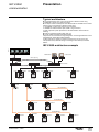

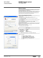

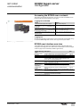
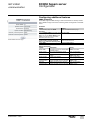
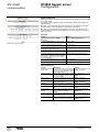


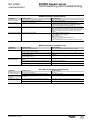
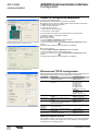

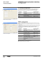
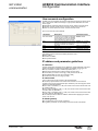
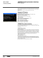

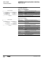
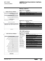
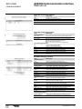
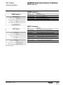
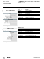


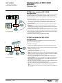
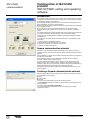
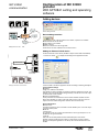


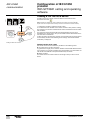
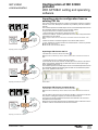
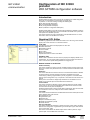
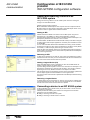

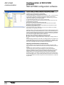


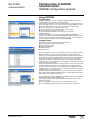
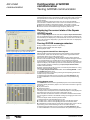
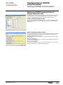

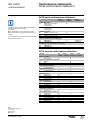


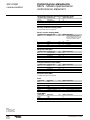


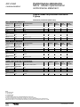
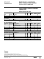
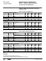
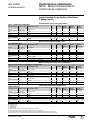

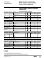
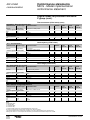
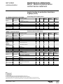

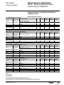
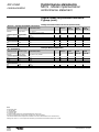
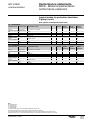
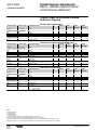
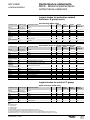
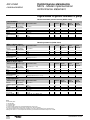
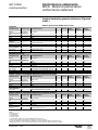
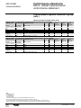
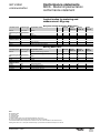
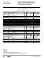
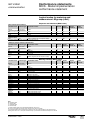

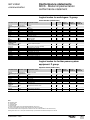


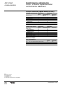
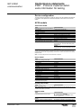
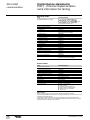


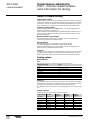

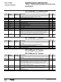


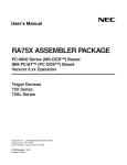


![[Unlocked] SC-2042](http://vs1.manualzilla.com/store/data/005660029_1-1367986a5e7a7fe673239a9957384234-150x150.png)