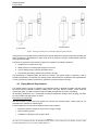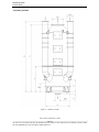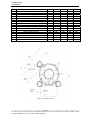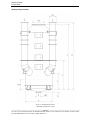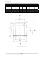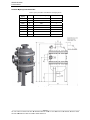
1
WÄRTSILÄ SCRUBBER PRODUCT GUIDE June 2014 REVISION A B C D DATE 08.03.10 28.12.11 20.09.13 30.06.14 APPROVED 24.07.14 J.Gannefors REVISION HISTORY DESCRIPTION Major revision Major revision Major revision THIS PUBLICATION IS DESIGNED TO PROVIDE AS ACCURATE AND AUTHORITATIVE INFORMATION REGARDING THE SUBJECTS COVERED AS WAS AVAILABLE AT THE TIME OF WRITING. HOWEVER, THE PUBLICATION DEALS WITH COMPLICATED TECHNICAL MATTERS AND THE DESIGN OF THE SUBJECT AND PRODUCTS IS SUBJECT TO REGULAR IMPROVEMENTS, MODIFICATIONS AND CHANGES. CONSEQUENTLY, THE PUBLISHER AND COPYRIGHT OWNER OF THIS PUBLICATION CANNOT TAKE ANY RESPONSIBILITY OR LIABILITY FOR ANY ERRORS OR OMISSIONS IN THIS PUBLICATION OR FOR DISCREPANCIES ARISING FROM THE FEATURES OF ANY ACTUAL ITEM IN THE RESPECTIVE PRODUCT BEING DIFFERENT FROM THOSE SHOWN IN THIS PUBLICATION. THE PUBLISHER AND COPYRIGHT OWNER SHALL NOT BE LIABLE UNDER ANY CIRCUMSTANCES, FOR ANY CONSEQUENTIAL, SPECIAL, CONTINGENT, OR INCIDENTAL DAMAGES OR INJURY, FINANCIAL OR OTHERWISE, SUFFERED BY ANY PART ARISING OUT OF, CONNECTED WITH, OR RESULTING FROM THE USE OF THIS PUBLICATION OR THE INFORMATION CONTAINED THEREIN. COPYRIGHT © 2014 BY WÄRTSILÄ MOSS AS. ALL RIGHTS RESERVED. NO PART OF THIS PUBLICATION MAY BE REPRODUCED OR COPIED IN ANY FORM OR BY ANY MEANS, WITHOUT PRIOR WRITTEN PERMISSION OF THE COPYRIGHT OWNER. ALL RIGHTS RESERVED. Wärtsilä Scrubber Product Guide Table of Contents 1 NOMENCLATURE & ABBREVIATIONS.................................................................................................................. 1 2 INTRODUCTION................................................................................................................................................................ 2 2.1 2.2 2.3 GENERAL ............................................................................................................................................................................ 2 SCRUBBER TYPES .............................................................................................................................................................. 2 SCRUBBER CONFIGURATIONS ......................................................................................................................................... 2 2.4 2.5 2.6 COMBUSTION UNITS ......................................................................................................................................................... 4 DIMENSIONING OF SCRUBBERS FOR A SPECIFIC GAS FLOW ........................................................................................ 5 2.3.1 2.3.2 2.3.3 2.3.4 3 MAIN STREAM SYSTEM ......................................................................................................................................................................... 2 INTEGRATED SYSTEM ........................................................................................................................................................................... 3 SINGLE INLET WITH VENTURI ............................................................................................................................................................... 3 MULTI-INLET WITH VENTURI ................................................................................................................................................................ 4 PERFORMANCE ................................................................................................................................................................... 4 RULES AND REGULATIONS........................................................................................................................................ 6 3.1 3.2 GENERAL ............................................................................................................................................................................ 6 IMO MARPOL.................................................................................................................................................................. 6 3.3 3.4 3.5 EU ...................................................................................................................................................................................... 8 US EPA: VESSEL GENERAL PERMIT (VGP) ................................................................................................................. 8 CLASSIFICATION SOCIETIES ........................................................................................................................................... 8 3.2.1 REGULATIONS ...................................................................................................................................................................................... 6 3.2.2 MARPOL DOCUMENTS ........................................................................................................................................................................ 7 4 SYSTEM DESCRIPTION ................................................................................................................................................ 9 4.1 CLOSED LOOP SEA WATER MAIN STREAM SYSTEM ........................................................................................................ 9 4.1.1 DESCRIPTION....................................................................................................................................................................................... 9 4.1.2 OPERATION ........................................................................................................................................................................................ 10 4.2 CLOSED LOOP SEA WATER INTEGRATED SYSTEM ........................................................................................................ 10 4.2.1 DESCRIPTION..................................................................................................................................................................................... 10 4.2.2 OPERATION ........................................................................................................................................................................................ 10 4.3 SINGLE AND MULTI-INLET OPEN LOOP SEA WATER SCRUBBERS ............................................................................... 11 4.3.1 DESCRIPTION..................................................................................................................................................................................... 11 4.3.2 OPERATION ........................................................................................................................................................................................ 12 4.4 SINGLE AND MULTI-INLET HYBRID SCRUBBERS ......................................................................................................... 12 4.4.1 DESCRIPTION..................................................................................................................................................................................... 12 4.4.2 OPERATION ........................................................................................................................................................................................ 13 4.5 SAFETY ............................................................................................................................................................................. 13 4.6 4.7 PIPING MATERIAL REQUIREMENTS ............................................................................................................................... 14 DIMENSIONS OF SCRUBBER UNIT, DEPLUME, RESIDENCE TANK AND HYDROCYCLONE ........................................... 15 4.7.1 GENERAL ........................................................................................................................................................................................... 15 4.7.2 HYBRID SCRUBBER SYSTEM ............................................................................................................................................................... 28 4.8 INSULATION ..................................................................................................................................................................... 28 5 EXHAUST GAS SYSTEM .............................................................................................................................................. 29 5.1 GENERAL .......................................................................................................................................................................... 29 5.1.1 5.1.2 5.1.3 5.1.4 5.2 5.3 MAIN STREAM SYSTEM ....................................................................................................................................................................... 29 INTEGRATED SYSTEM ......................................................................................................................................................................... 29 EXHAUST GAS BACK PRESSURE .......................................................................................................................................................... 29 NOISE ATTENUATION ......................................................................................................................................................................... 29 SINGLE INLET SYSTEM .................................................................................................................................................... 29 MULTI INLET SYSTEM ...................................................................................................................................................... 30 5.3.1 EXHAUST GAS FAN ............................................................................................................................................................................. 30 5.4 BYPASS DAMPER .............................................................................................................................................................. 32 5.4.1 BYPASS DAMPER DESIGN.................................................................................................................................................................... 32 5.4.2 BYPASS DAMPER CONTROL AND MONITORING .................................................................................................................................... 34 5.4.3 BYPASS DAMPER SEALING AIR SYSTEM ............................................................................................................................................... 35 5.4.4 BYPASS DAMPER OUTDOOR INSTALLATION ......................................................................................................................................... 35 5.5 PLUME ENCLOSURE ......................................................................................................................................................... 36 5.6 5.7 6 EXHAUST GAS PIPES ....................................................................................................................................................... 36 INTERCONNECTING OF EXHAUST GAS PIPES ................................................................................................................ 37 SCRUBBING WATER SYSTEMS .............................................................................................................................. 38 NO PART OF THIS PUBLICATION MAY BE REPRODUCED OR COPIED IN ANY FORM OR BY ANY MEANS, WITHOUT PRIOR WRITTEN PERMISSION OF THE COPYRIGHT OWNER WÄRTSILÄ. Wärtsilä Scrubber Product Guide 7 SEA WATER COOLING SYSTEM – CLOSED LOOP ....................................................................................... 39 8 MAKE-UP WATER SYSTEM – CLOSED LOOP .................................................................................................. 40 8.1 8.2 8.3 9 GENERAL .......................................................................................................................................................................... 40 WATER QUALITY .............................................................................................................................................................. 40 UV-FILTER....................................................................................................................................................................... 40 BLEED-OFF, EFFLUENT AND SLUDGE SYSTEM – CLOSED LOOP ....................................................... 41 9.1 9.2 GENERAL .......................................................................................................................................................................... 41 DAF BLEED-OFF TREATMENT UNIT ............................................................................................................................... 41 9.3 9.4 9.5 9.6 HOLDING TANK ................................................................................................................................................................ 47 BLEED-OFF PIPING .......................................................................................................................................................... 47 SLUDGE ............................................................................................................................................................................ 48 9.2.1 9.2.2 9.2.3 9.2.4 9.2.5 DESCRIPTION..................................................................................................................................................................................... 41 BUFFER TANK ..................................................................................................................................................................................... 41 BLEED-OFF RECIRCULATION PUMP ...................................................................................................................................................... 41 PRE-CONDITIONING WATER ............................................................................................................................................................... 42 TECHNICAL DATA ............................................................................................................................................................................... 43 CENTRIFUGAL SEPARATOR BLEED-OFF TREATMENT UNIT .......................................................................................... 44 10 ALKALI SYSTEM – CLOSED LOOP ........................................................................................................................ 49 10.1 10.2 10.3 10.4 10.5 10.6 10.7 10.8 10.9 GENERAL .......................................................................................................................................................................... 49 CONSUMPTION ................................................................................................................................................................ 50 STORAGE.......................................................................................................................................................................... 50 TANK COATING ................................................................................................................................................................ 52 STORAGE TANK HEATING ............................................................................................................................................... 53 STORAGE TANK FITTINGS AND INSTRUMENTS ............................................................................................................. 54 ALKALI FEED MODULE ..................................................................................................................................................... 55 ALKALI TRANSFER PUMP ................................................................................................................................................. 56 ALKALI SPECIFICATION................................................................................................................................................... 56 11 SCRUBBING WATER SYSTEMS – OPEN LOOP .............................................................................................. 58 11.1 GENERAL .......................................................................................................................................................................... 58 11.2 SEA WATER QUALITY....................................................................................................................................................... 58 11.3 SEA WATER FLOW ........................................................................................................................................................... 58 12 WASH WATER AND SLUDGE SYSTEM................................................................................................................ 59 12.1 WASH WATER SYSTEM .................................................................................................................................................. 59 12.2 RESIDENCE TANK ............................................................................................................................................................ 59 12.3 SLUDGE SYSTEM ............................................................................................................................................................. 60 13 AUTOMATION................................................................................................................................................................... 62 13.1 DEFINITIONS ................................................................................................................................................................... 62 13.2 GENERAL DESCRIPTION .................................................................................................................................................. 62 13.2.1 CONTROL SYSTEM PHILOSOPHY ..................................................................................................................................................... 62 13.2.2 ELECTRICAL AND AUTOMATION PANELS.......................................................................................................................................... 62 13.2.3 SYSTEM BLOCK DIAGRAM............................................................................................................................................................... 62 13.2.4 LIST OF COMPONENTS/PANELS ...................................................................................................................................................... 63 13.2.5 LIST OF CONTROL & MONITORED POINTS ...................................................................................................................................... 64 13.2.6 SYSTEM ALARMS ............................................................................................................................................................................ 64 13.2.7 SECOND ALARM ............................................................................................................................................................................. 64 13.3 SYSTEM CONFIGURATION ............................................................................................................................................... 65 13.3.1 COMMUNICATION .......................................................................................................................................................................... 65 13.3.2 REDUNDANT POWER SUPPLY ......................................................................................................................................................... 66 13.4 MAIN AUTOMATION EQUIPMENT AND CONTROL ........................................................................................................... 67 13.4.1 ELECTRICAL AND AUTOMATION PANELS (WÄRTSILÄ)..................................................................................................................... 67 13.4.2 ELECTRICAL AND AUTOMATION PANELS (SUB SUPPLIER) .............................................................................................................. 70 13.4.3 PLC............................................................................................................................................................................................... 71 13.4.4 REMOTE I/O.................................................................................................................................................................................. 71 13.5 NETWORK SWITCH .......................................................................................................................................................... 72 13.5.1 OPERATOR SCREEN ........................................................................................................................................................................ 72 13.5.2 DATA LOGGER ............................................................................................................................................................................... 73 NO PART OF THIS PUBLICATION MAY BE REPRODUCED OR COPIED IN ANY FORM OR BY ANY MEANS, WITHOUT PRIOR WRITTEN PERMISSION OF THE COPYRIGHT OWNER WÄRTSILÄ. Wärtsilä Scrubber Product Guide 13.5.3 STARTERS ..................................................................................................................................................................................... 73 13.6 OPERATOR STATION ....................................................................................................................................................... 73 13.7 FALLBACK STATE – BEHAVIOR IN THE EVENT OF A NETWORK FAULT ........................................................................ 74 13.7.1 DISTRIBUTED IO (STB NIP 2311) .............................................................................................................................................. 74 13.7.2 MOTOR STARTER (TESYST LTM R)............................................................................................................................................... 74 13.7.3 MOTOR STARTER VSD (ALTIVAR 61) ........................................................................................................................................... 74 13.8 EMERGENCY STOP AND SAFETY SHUTDOWN ................................................................................................................ 75 13.8.1 EMERGENCY STOP ......................................................................................................................................................................... 75 13.8.2 SAFETY SHUTDOWNS ..................................................................................................................................................................... 76 13.8.3 BLACK-OUT ARRANGEMENT............................................................................................................................................................ 76 13.9 SYSTEM INTERFACES ...................................................................................................................................................... 76 13.9.1 COMMON ALARM ............................................................................................................................................................................ 76 13.9.2 SHIP CONTROL SYSTEM (IAS, PMS, GPS…) ................................................................................................................................ 76 13.10 EMERGENCY OPERATIONS .......................................................................................................................................... 77 13.11 REDUNDANCY .............................................................................................................................................................. 77 14 MISCELLANEOUS ........................................................................................................................................................... 78 14.1 POWER DEMAND .............................................................................................................................................................. 78 14.2 MAINTENANCE ................................................................................................................................................................. 78 15 APPENDIXES .................................................................................................................................................................... 80 15.1 APPENDIX: NAOH .......................................................................................................................................................... 80 15.1.1 GENERAL ....................................................................................................................................................................................... 80 15.1.2 SAFETY ASPECTS ........................................................................................................................................................................... 80 15.1.3 DELIVERY ...................................................................................................................................................................................... 81 15.2 APPENDIX: SCRUBBER NOMENCLATURE ...................................................................................................................... 82 NO PART OF THIS PUBLICATION MAY BE REPRODUCED OR COPIED IN ANY FORM OR BY ANY MEANS, WITHOUT PRIOR WRITTEN PERMISSION OF THE COPYRIGHT OWNER WÄRTSILÄ. Wärtsilä Scrubber Product Guide Table of Figures Figure 1: - Main Stream Scrubber ............................................................................................................................. 2 Figure 2: - Integrated Scrubber ................................................................................................................................. 3 Figure 3: - Single inlet system with a venturi ............................................................................................................. 4 Figure 4: - Multi inlet system with venturies .............................................................................................................. 4 Figure 5: - Closed loop sea water system principle diagram ..................................................................................... 9 Figure 6: - Open Loop sea water system principle diagram .................................................................................... 11 Figure 7: - Multi inlet scrubber................................................................................................................................. 12 Figure 8: - Hybrid Scrubber ..................................................................................................................................... 13 Figure 9: - Exhaust gas cleaning unit in normal mode (right) and bypass mode (left) ............................................. 14 Figure 10: - Single entry scrubber ........................................................................................................................... 16 Figure 11: - Single entry scrubber ........................................................................................................................... 17 Figure 12: - Double Entry Scrubber ........................................................................................................................ 18 Figure 13: - Double Entry scrubber ......................................................................................................................... 20 Figure 14: - Triple Entry Scrubber ........................................................................................................................... 21 Figure 15: - Triple Entry Scrubber ........................................................................................................................... 22 Figure 16: - Quadruple Entry Scrubber ................................................................................................................... 23 Figure 17: - Quadruple Entry Scrubber ................................................................................................................... 24 Figure 18: - Deplume mixing unit dimensions ......................................................................................................... 25 Figure 19: - Residence tank dimensions ................................................................................................................. 26 Figure 20: - Hydrocyclone figures ........................................................................................................................... 27 Figure 21: - Exhaust gas fan dimensional drawing.................................................................................................. 31 Figure 22: - Example of exhaust gas fan pressure in double fan configuration ....................................................... 32 Figure 23: - Bypass damper with 60° angle to scrubber .......................................................................................... 33 Figure 24: - Bypass damper with 90° angle to scrubber .......................................................................................... 34 Figure 25: - Weather cover to be used in outdoor installations ............................................................................... 35 Figure 26: - Bleed-off treatment unit in one piece ................................................................................................... 42 Figure 27: - Bleed-off treatment unit with separated chemical modules .................................................................. 43 Figure 28: - Bleed-off treatment unit recommended service space ......................................................................... 43 Figure 29: - Centrifugal Separator ........................................................................................................................... 45 Figure 30: - Separator service space requirements ................................................................................................ 46 Figure 31: - Centrifugal Separator installation ......................................................................................................... 47 Figure 32: - Residence tank .................................................................................................................................... 60 Figure 33: - “Corrosive” sign. .................................................................................................................................. 49 Figure 34: - Safety shower and eye wash signs ...................................................................................................... 49 Figure 35: - Alkali consumption per operating power .............................................................................................. 50 Figure 36: - Alkali consumption per consumed fuel................................................................................................. 51 Figure 37: - Caustic soda storage tank fittings ........................................................................................................ 55 Figure 38: - Example of “spray protector” plate for alkali storage tank air and overflow pipe................................... 55 Figure 39: - Sludge tank.......................................................................................................................................... 61 Figure 40: - Alarm connection principle ................................................................................................................... 64 Figure 41: - Communication .................................................................................................................................... 65 Figure 42: - Redundant Power Supply .................................................................................................................... 66 Figure 43: - Overview of the +MCP ......................................................................................................................... 67 Figure 44: - Emergency stop ................................................................................................................................... 75 Figure 45: - Solidification temperature of NaOH solution. ....................................................................................... 80 NO PART OF THIS PUBLICATION MAY BE REPRODUCED OR COPIED IN ANY FORM OR BY ANY MEANS, WITHOUT PRIOR WRITTEN PERMISSION OF THE COPYRIGHT OWNER WÄRTSILÄ. Wärtsilä Scrubber Product Guide 1 Nomenclature & Abbreviations The following is a list of abbreviations used in this document. Detailed terminology is presented in Chapter 15.2 Scrubber Nomenclature. AWP BOTU CEMS EGC EGC Unit EGD EMM ETM A/B FNU HMI IAMCS IMO I/O MARPOL MCP MCR OMM PLC SECA SECP SWMM VSD WWMM CO2 SO2 NaOH Advanced water purification Bleed-off treatment unit Continuous emission monitoring system Exhaust Gas Cleaning Exhaust Gas Cleaning Unit, also known as a Scrubber. Exhaust Gas Declaration Effluent monitoring module (Closed loop) Exhaust Gas Cleaning Technical Manual for Scheme A/B Unit used for measuring turbidity Human-Machine Interface – automation system Ship automation system International Maritime Organization Input / Output (referring to communication terminals) The International Convention for the Prevention of Pollution from Ships Main control panel (for scrubber automation) Maximum continuous rating Onboard Monitoring Manual Programmable logic controller SOx Emission Control Area SOx Emissions Compliance Plan Sea water monitoring module Variable speed drive Wash water monitoring module Carbon dioxide Sulphur dioxide Caustic soda (Alkali) Page 1 NO PART OF THIS PUBLICATION MAY BE REPRODUCED OR COPIED IN ANY FORM OR BY ANY MEANS, WITHOUT PRIOR WRITTEN PERMISSION OF THE COPYRIGHT OWNER WÄRTSILÄ. Wärtsilä Scrubber Product Guide 2 Introduction 2.1 General This Product Guide describes the technical installation matters related to exhaust gas cleaning systems used for Sulphur emission control purposes in marine environment. This guide is intended to give technical support in the early design phase. Any data and information herein is subject to revision without notice. For contracted projects, specific instructions are delivered. This document provides general guidance regarding scrubber onboard space reservation, system and tank design and other similar issues. 2.2 Scrubber types This Product Guide covers open loop sea water systems, closed loop sea water systems and hybrid sea water systems. Other scrubber systems are under development, and will be included in the later revisions of this Product Guide. 2.3 Scrubber Configurations There are four types of configurations: Main Stream system, Integrated System, Single Venturi systems and Multiple Venturi systems. All these configurations can work as open or closed loop systems, and can be fitted to both new buildings and retrofit installations. 2.3.1 Main stream system Figure 1: - Main Stream Scrubber Page 2 NO PART OF THIS PUBLICATION MAY BE REPRODUCED OR COPIED IN ANY FORM OR BY ANY MEANS, WITHOUT PRIOR WRITTEN PERMISSION OF THE COPYRIGHT OWNER WÄRTSILÄ. Wärtsilä Scrubber Product Guide Main Stream systems are designed to be installed in the main exhaust gas stream of an individual combustion unit. This solution is advantageous for a range of machinery configurations, for example for single main engines in ships where auxiliary generator engines and oil-fired boilers use compliant fuel. 2.3.2 Integrated system An Integrated system is designed to clean the exhaust gases originating from several main and/or auxiliary engines in one scrubber unit. Integrated systems are typically provided with exhaust gas fans to compensate the additional back pressure created by the exhaust gas cleaning unit(s). An Integrated scrubber is suitable for all types of ships, especially for those with several main engines, ships with single main engines and generator engines using heavy fuel oil, and diesel-electric ships. Figure 2: - Integrated Scrubber 2.3.3 Single inlet with venturi Single inlet system has one exhaust gas entry from an individual fuel oil combustion unit, which typically makes it a main stream system, although in some cases it is also possible to combine exhaust gas pipes from several combustion units into one main pipe before the single venturi. Single inlet configuration provides the most flexible solution for most machinery arrangements. For very large engine power output, where the power rating exceeds the maximum scrubber size currently available, multiple scrubbers can be utilized to share the exhaust gas output from such machinery. Page 3 NO PART OF THIS PUBLICATION MAY BE REPRODUCED OR COPIED IN ANY FORM OR BY ANY MEANS, WITHOUT PRIOR WRITTEN PERMISSION OF THE COPYRIGHT OWNER WÄRTSILÄ. Wärtsilä Scrubber Product Guide Figure 3: - Single inlet system with a venturi 2.3.4 Multi-inlet with venturi Multi-inlet systems with a maximum of four exhaust gas connections can be used to clean the exhaust gases from multiple fuel oil combustion units. In general terms this type of scrubber is supported with the use of a fan to assist in controlling the exhaust gas flow directions especially away from non-running machinery. Figure 4: - Multi inlet system with venturies 2.4 Performance As a default, the scrubber system is designed for maximum Sulphur content in the fuel of 3.50%. The SOx reduction efficiency corresponds to a reduction of fuel Sulphur content from 3.50% to 0.10%. This is a typical guaranteed performance of the system. Other alternatives can be offered following discussion with Wärtsilä. 2.5 Combustion units Combustion units can be diesel engines of any make, type or application, 2-stroke or 4-stroke. Oil fired boilers can also be connected to a main stream scrubber. Combustion unit gas flow and temperature throughout the load range are needed to determine appropriate scrubber configuration. Also exhaust gas back pressure measurement information is needed especially in main stream scrubber retrofit installations. Wärtsilä can provide assistance in back pressure measurement. Page 4 NO PART OF THIS PUBLICATION MAY BE REPRODUCED OR COPIED IN ANY FORM OR BY ANY MEANS, WITHOUT PRIOR WRITTEN PERMISSION OF THE COPYRIGHT OWNER WÄRTSILÄ. Wärtsilä Scrubber Product Guide 2.6 Dimensioning of scrubbers for a specific gas flow As a general rule, scrubbers should be dimensioned for 100% of the gas flow of the connected combustion unit(s). An Integrated Scrubber can be dimensioned for a smaller gas flow than the total exhaust gas of the connected combustion units. This could be the case when all generator engines are connected to the scrubber, as generally not all generator engines are fully loaded simultaneously. This arrangement will require agreement between the Owner / Operator and the relevant Classification Society, and will be detailed in an Exhaust Gas Declaration (EGD). Subject to confirmation from the classification society, a scrubber (Main Stream, Integrated or Multi-inlet) can be dimensioned for a smaller gas flow than the exhaust gas of the combustion unit(s) at full load, provided that such a compliance principle is based on a realistic operating mode. In such cases the SECP and EGD should specify operating modes when the ship is compliant by fuel and when by scrubbing. Any engine load exceeding the scrubber capacity would automatically open the exhaust gas bypass line, and the ship is responsible for compliance. Adjusting the set point of the load control system of main propulsion engines or generator engines normally used on ships to a value corresponding to the scrubber capacity is a convenient way of ensuring that the scrubber capacity is not exceeded, and the ship stays in “scrubber compliance mode”. Page 5 NO PART OF THIS PUBLICATION MAY BE REPRODUCED OR COPIED IN ANY FORM OR BY ANY MEANS, WITHOUT PRIOR WRITTEN PERMISSION OF THE COPYRIGHT OWNER WÄRTSILÄ. Wärtsilä Scrubber Product Guide 3 Rules and regulations 3.1 General The core purpose behind exhaust gas cleaning is the global need to reduce the amount of Sulphur oxides being emitted to the atmosphere by combustion units using fuels containing Sulphur. Several major marine legislators have recently imposed rules and regulations concerning different methods of limiting the Sulphur footprint generated by marine traffic. These new rules not only limit the amount of Sulphur ships are allowed to emit into the atmosphere, but also set a variety of discharge water quality requirements for the exhaust gas cleaning systems being used. The following list details the main legislative requirements having an effect on the use of exhaust gas cleaning: The International Maritime Organization (IMO) o Marpol Annex VI o Resolution MEPC.184(59) Guidelines for Exhaust Gas Cleaning Systems European Union (EU) o EU Sulphur Directive 2012/33/EU o EU Marine Equipment Directive (MED) 96/98/EC as amended by 2012/32/EU US EPA Vessel General Permit Classification society requlations 3.2 IMO MARPOL 3.2.1 Regulations The IMO Annex VI serves as the base of worldwide marine sulphur reduction requirements. IMO MARPOL legislation limits the use of fuels containing sulphur as follows: Global limit sulphur %: 3.50% from 1.1.2012 0.50% from 1.1.2020, possibly to be postponed to 1.1.2025. Emission Control Areas sulphur %: 1.00% from 1.7.2010 0.10% from 1.1.2015 Fuel types are not regulated, leaving also room for alternative compliant solutions such as exhaust gas cleaning (ref: MARPOL Annex VI Regulation 4). The discharge water quality restrictions have been defined in the IMO Scrubber Guidelines MEPC.184(59), launched in 2009. The following discharge water qualities have been given limit values: pH PAH Turbidity Nitrates Page 6 NO PART OF THIS PUBLICATION MAY BE REPRODUCED OR COPIED IN ANY FORM OR BY ANY MEANS, WITHOUT PRIOR WRITTEN PERMISSION OF THE COPYRIGHT OWNER WÄRTSILÄ. Wärtsilä Scrubber Product Guide 3.2.2 MARPOL Documents The MEPC.184(59) lists a variety of documents to be generated for a ship using exhaust gas cleaning as means of meeting the emission legislation requirements. These documents must be approved by the Administration. The following contains a short summary of the documents: SECP The SOx Emissions Compliance Plan is a document describing all the possible alternatives of the particular ship is capable of using in order to meet the emission requirements set for the sulphur emission control areas (SECAs). These alternatives mainly consist of 3 different scenarios, which are; 1) Using compliant fuel (<0.10%S), 2) Using different fuels inside and outside SECA – areas (<0.10%S inside SECA), and 3) Using an EGC System. The SECP also lists all the combustion units onboard and which of them are connected to the exhaust gas cleaning unit(s). ETM-A/B Under MEPC.184(59) there are two possible compliance routes, Scheme A or Scheme B; 1) Scheme A – EGC System Approval, Survey and Certification using Parameter and Emission Checks, 2) Scheme B – EGC System Approval, Survey and Certification using Continuous Monitoring of Emissions. The ETM-A/B is the main technical manual that describes a variety of relevant key process parameters of the particular exhaust gas cleaning system. These key border-values have been confirmed by the administration, meaning that when the exhaust gas cleaning system is being used, it should stay within the limits at all times to ensure compliance. The ETM also states the corrective actions to be performed in case exceedances are occurring. OMM The Onboard Monitoring Manual is a document listing all the essential sensors used to demonstrate system compliance. These sensors mainly consist of exhaust gas monitoring, key-process parameters (such as scrubbing water pressure and flow) and discharge water quality monitoring. The OMM states all the service, maintenance and calibration requirements for these essential sensors together with the component / sensor part manuals. These service, maintenance & calibration tasks must be performed in due time and the corresponding notes must be written in the EGC Record Book. With completed records, the ship is able to effectively demonstrate that the EGC system is working in compliance and that the sensor values used to determine compliance are trustworthy. The OMM also states how the monitoring system surveys are to be performed. EGC Record Book The EGC Record Book is a set of forms that are required to be used to log events affecting and repairs to the sensors monitoring EGC System compliance. Such events are for example all the service, maintenance and re-calibration that is being done for the sensors listed in the OMM, when wash water residues/sludge is being offloaded to a port reception facility or in the case of closed loop the delivery of and consumption of chemicals for maintaining system performance (e.g. Sodium Hydroxide [Caustic Soda] NaOH). As an alternative to using the EGC Record Book, similar log can be kept as a part of the ship’s Planned Maintenance System (PMS). Exhaust gas declaration This document states the exhaust gas flow values from the connected engines to be used to determine EGC System capacity requirements. Page 7 NO PART OF THIS PUBLICATION MAY BE REPRODUCED OR COPIED IN ANY FORM OR BY ANY MEANS, WITHOUT PRIOR WRITTEN PERMISSION OF THE COPYRIGHT OWNER WÄRTSILÄ. Wärtsilä Scrubber Product Guide 3.3 EU The European Union has introduced a Sulphur Directive, which has great impact on the local marine traffic inside EU SECAs. This directive is mostly following the IMO MARPOL Annex VI, with a few additional requirements. Summary of the EU Sulphur directive, applicable to ships of all flags: All ships in SOx ECA o 1.00% until 31.12.2014 o 0.10% from 1.1.2015 All ships outside SOx ECA o 3.50% from 1.1.2012 o 0.50% from 1.1.2020 Passenger vessels operating on regular services to or from EU port o 1.5% until 1.1.2020 Ships at berth in EU o 0.1% from 1.1.2010 3.4 US EPA: Vessel General Permit (VGP) From December 19th 2013, commercial ships operating closer than 3 miles from US coast line, must obtain coverage under Vessel General Permit in order to be allowed to discharge into the sea. The allowed discharge limits are similar to the IMO legislations in terms of having limit values for pH, PAH, Turbidity, Nitrates and Nitrites. The discharge of washwater from the exhaust gas scrubber treatment system must have a pH of no less than 6.0 measured at the ship’s overboard discharge, with the exception that during maneuvering and transit, the maximum difference between inlet and outlet of 2.0 pH units is allowed. This difference is to be measured at the ship’s inlet and overboard discharge. 3.5 Classification Societies Several Classification Societies have already developed their own rules to incorporate the use of emissions abatement technology and to ensure that the use of this equipment will have no adverse effect on the safety of the ship. In terms of MARPOL compliance, most Classification Societies are designated as Recognised Organisations and are able to act on behalf of Flag State Administrations and are given a mandate to survey and verify emission abatement system compliance on their behalf. Point worth noticing is that the rules concerning Exhaust Gas Cleaning Systems developed by different Class Societies may differ between each other. Page 8 NO PART OF THIS PUBLICATION MAY BE REPRODUCED OR COPIED IN ANY FORM OR BY ANY MEANS, WITHOUT PRIOR WRITTEN PERMISSION OF THE COPYRIGHT OWNER WÄRTSILÄ. Wärtsilä Scrubber Product Guide 4 Systtem Des scriptio on 4.1 Closed lo oop sea water w main n stream s system 4.1.1 De escription In Closed lo oop scrubbin ng process, the scrubbing g water is pu umped through a sea wa ater heat excchanger to th he scrubber. S Scrubbing wa ater is sprayyed towards the exhaustt gas flow viia spray nozzzles inside the scrubbe er. Scrubbing w water is also sprayed to the t venturi ex xhaust gas in nlet(s). Scrubbing water w passes s through the e packed bed d inside the scrubber and d is eventually collected and remove ed through the e sump at the bottom. The scrubbing g water abso orbs Sulphur oxides, heat and otherr componentts from the exxhaust gas sttream. The heat h is remo oved in a sea a water heat exchanger. Scrubbing water w pH, an nd thus the cle eaning efficiency, is autom matically mon nitored and controlled c by y alkali dosing g. ubber overall dimensionss, together with w space fo or the auxilia ary equipme ent and main ntenance, arre As the scru exceeding e e.g. conventiional silencer dimensionss, a slightly la arger engine e casing area a may be req quired. In new w building pro ojects, it is im mportant thatt functionality of the EGC C system is considered in the ship p project desig gn phase in ord der to provide efficient sccrubber syste em together with optimize ed space utillization. Figure re 5: - Closed loo op sea water syystem principle diagram d process princ ciple is similar for both main m stream and integra ated scrubbers. When co omparing sub bThe basic p systems, most differencces can be fo ound in the ex xhaust gas system. s Each sub-syystem will be e discussed in more deta ail under ded dicated chap pters in this document d highlighting th he differences in each conffiguration as necessary. Page 9 NO PART OF F THIS PUBLIC CATION MAY BE B REPRODUC CED OR COPIE ED IN ANY FO ORM OR BY AN NY MEANS, WITHOUT W PRIO OR WRITTEN PER RMISSION OF THE T COPYRIG GHT OWNER WÄRTSILÄ. W Wärtsilä Scrubber Product Guide 4.1.2 Operation The scrubber is designed for continuous operation at full specified gas flow. Main stream scrubbers are typically dimensioned for 100% engine load. Typically the system is specified for following operation: Any fuel Sulphur content up to 3.50%. Any load not exceeding the design load. Exhaust gas cleaned to a level where exhaust gas SOX-emission is not exceeding an equivalent of fuel Sulphur content of 0.10%. Temporary operation without sea water cooling. In such case the water consumption and the exhaust gas back pressure are higher, and the exhaust gas plume is more visible. The water content in the exhaust gas is higher, and the risk of condensation and droplets is higher if the exhaust pipe after the scrubber is not insulated. Operation at full load should be avoided without cooling water. The following operation modes are not permitted: Using fuel with Sulphur content exceeding 3.50%. Exceeding the design load. Dry running of scrubber (hot exhaust gases are not allowed to enter scrubber when the scrubbing water is not circulated). However, the scrubber can be bypassed by closing the exhaust branches to scrubber. In such cases compliance with the regulations is to be achieved by using fuel with appropriate Sulphur content. Wet running of scrubber with alkali injection out of operation. 4.2 Closed loop sea water integrated system 4.2.1 Description An ideal location for an integrated scrubber, serving several combustion units, is aft of or within funnel casing. This arrangement gives a minimum loss of useable cargo or accommodation space with functional gas flow and access to main components. Rest of the exhaust systems and casing are following conventional design with silencers installed before scrubber intake. 4.2.2 Operation Operation is similar to main stream sea water system, but with certain consideration to machinery operational profile. It may not be necessary to dimension the integrated scrubber according to installed machinery power as such dimensioning may result in unnecessary over-dimensioning as the installed power is not operated in practice. In order to dimension the integrated scrubber system properly it is relevant to identify the maximum propulsion (full speed) and electrical power as well as heat demand of the ship (refer to section 2.6 above). In case of integrated scrubber, the maximum exhaust gas flow is designed to cover all relevant operating modes, as presented in the example: Sea going: Main engine(s) at 100 % MCR + generator engine(s) load, (unless shaft generator(s) are expected to be used in this operating mode). Sea going (Diesel-Electric machinery): Generator engines providing full propulsion and hotel power. In port: Generator engine(s) at highest possible relevant load. In most cases the sea going conditions result in the highest possible gas flow to be used as design criteria. The design conditions for integrated scrubbers should be examined case by case for accurate dimensioning. Page 10 NO PART OF THIS PUBLICATION MAY BE REPRODUCED OR COPIED IN ANY FORM OR BY ANY MEANS, WITHOUT PRIOR WRITTEN PERMISSION OF THE COPYRIGHT OWNER WÄRTSILÄ. Wärtsilä Scrubber Product Guide 4.3 Single an nd Multi-in nlet open loop sea water w scru ubbers 4.3.1 De escription The system m is sea wate er based, operating in op pen loop dessigned to use e the natural buffering ca apacity of se ea water for the e removal off SOx. Figurre 6: - Open Loo op sea water syystem principle diagram d ber can be sited s in eithe er the engin ne casing orr funnel, dep pending upo on the space e available or o The scrubb specific requirements off the client downstream d of o other com mponents succh as silence ers and/or ecconomizers in i m. Exhaust gas inlets are e arranged via a venturi or o a series off venturi’s sited at the sid de the exhaustt gas system of the scrub bber, genera ally in the ve ertical plane but other po ositions can be considerred during planning of th he system spe ecification an nd layout. In multi inlet systems, the system is tyypically provided with an n exhaust ga as fan while in the single in nlet system, the necessity of an exha aust fan is mo ore dependin ng on the co ombustion un nit and the resu ulting back pressure p of th he complete exhaust pipiing. Page 11 NO PART OF F THIS PUBLIC CATION MAY BE B REPRODUC CED OR COPIE ED IN ANY FO ORM OR BY AN NY MEANS, WITHOUT W PRIO OR WRITTEN PER RMISSION OF THE T COPYRIG GHT OWNER WÄRTSILÄ. W Wärtsilä Scrubber Product Guide Figure 7: - Multi inlet scrubber 4.3.2 Operation The scrubbers are designed for continuous operation at the full specified exhaust gas flow. All scrubbers are typically dimensioned for 100% of the exhaust gas capacity of the connected machinery. Where this exceeds the current design parameters for scrubbers; multiple scrubbers would be specified to share the required gas capacity (refer to section 2.6 above). Typical design specification is for the following operation: Any fuel Sulphur content of up to 3.50%. Any machinery load up to design maximum load. Exhaust gas cleaned to a level where exhaust gas SOx-emission is not exceeding an equivalent of fuel Sulphur content 0.10% Continuous operation. Operation in by-pass mode. The following operating modes are not permitted: Consumption of fuel with Sulphur level exceeding 3.50%, without prior agreement with Wärtsilä. Exceeding maximum design load of the connected machinery, or limits stated in the Exhaust Gas Declaration. Prolonged dry running of the scrubber. 4.4 Single and Multi-inlet Hybrid Scrubbers 4.4.1 Description Wärtsilä Hybrid scrubbers are a combination of open loop and closed loop sea water scrubbers. Both methods, open loop and closed loop, are operated using only sea water as scrubbing water. During closed loop operation, caustic soda (sodium hydroxide, NaOH) is added to the scrubbing circulation water. In both operation modes, the scrubbing water is released back to the sea after it has been processed in water treatment plants. However, in closed loop operation, the scrubbing water is recycled several times within the system and the amount of wash water produced and sea water consumed is thus minimized. Due to the minimized effluent flow of closed loop operation, a “zero discharge mode”, where no discharge to sea exists, is possible by directing the effluent flow in to a holding tank. Page 12 NO PART OF THIS PUBLICATION MAY BE REPRODUCED OR COPIED IN ANY FORM OR BY ANY MEANS, WITHOUT PRIOR WRITTEN PERMISSION OF THE COPYRIGHT OWNER WÄRTSILÄ. Wärtsilä Scrubber Product Guide Figurre 8: - Hybrid Sccrubber 4.4.2 Op peration As the same e scrubbing water pumpss, piping and d nozzles are e being used d in both ope eration modes, Open Loo op mode and Closed C Loop mode canno ot be used simultaneously. In most app plications it is possible to o shut off on ne spray nozzzle layer during closed loop operatio on in order to t save electric power use ed for pumpin ng. The feassibility of this operation with w less scru ubbing water is dependen nt on the actua al scrubbing water pump configuratio on. 4.5 Safety The figure b below shows s the principle of the exha aust gas cleaning bypass function: A fail safe thrree-way valvve directs the exhaust flow w to a bypasss line to se ecure ship maneuverabi m lity also in any a possible e exhaust ga as cleaning unit or subsystem failure sccenario. Page 13 NO PART OF F THIS PUBLIC CATION MAY BE B REPRODUC CED OR COPIE ED IN ANY FO ORM OR BY AN NY MEANS, WITHOUT W PRIO OR WRITTEN PER RMISSION OF THE T COPYRIG GHT OWNER WÄRTSILÄ. W Wärtsilä Scrubber Product Guide Figure 9: - Exhaust gas cleaning unit in normal mode (right) and bypass mode (left) The bypass line is controlled with a fail-safe three-way bypass damper: the damper is kept open (directing gas flow to scrubber) by compressed air or other media, and it is closed by a spring or similar positive means not requiring external energy. The flow to the scrubber is closed and the bypass line is opened in the following situations: 1. Temperature in scrubber is too high. 2. Water pressure in scrubbing water supply line is too low. 3. Loss of holding energy in exhaust gas bypass valve. 4. The exhaust gas cleaning system back pressure is too high. The temperature is measured before and after the scrubber. The bypass damper is opened in case of excessive temperature. The exhaust gas cleaning system back pressure is measured at the bypass damper or at the scrubber inlet and the bypass line is opened if the pressure reading is too high. 4.6 Piping Material Requirements This chapter applies to piping not installed in gas hazardous areas, in particular for plastic and GRE (Glass Re-enforced Epoxy) materials, including scrubbing water, sea water, bleed-off, effluent, caustic soda and exhaust gas piping. The latter is subject to approved safety arrangements to prevent overheating. All the piping, penetrations, etc. is constructed according to classification society’s rules. All piping is in Class III, except caustic soda piping which is Class I. Fire endurance requirements With the exception of the exhaust gas bypass line, exhaust gas cleaning system ancillary pipes are not essential for the operation of a diesel engine. There are therefore no fire endurance requirements for pipes located in: Machinery spaces of category A (engine rooms, engine casings) Other machinery spaces Cofferdams, void spaces, pipe tunnels or ducts Page 14 NO PART OF THIS PUBLICATION MAY BE REPRODUCED OR COPIED IN ANY FORM OR BY ANY MEANS, WITHOUT PRIOR WRITTEN PERMISSION OF THE COPYRIGHT OWNER WÄRTSILÄ. Wärtsilä Scrubber Product Guide On open decks Flame spread characteristics All pipes, except those fitted on open decks and within tanks, cofferdams, pipe tunnels and ducts shall have low surface flame spread characteristics not exceeding average values listed in IMO Resolution A.653 (16). Surface flame spread characteristics may be determined using the test procedures given in ASTM D3806. UV-resistance For systems exposed to sunlight on open decks, the material has to be UV-resistant or otherwise protected against UV-radiation. This does not apply to insulated or otherwise enclosed pipes. Heat distortion Heat distortion temperature is determined according to ISO 75 method A, or equivalent. Pressure requirements All pipe work is to be rated for at least the designed working pressure. In particular GRE pipe work passing through ballast tanks or any other tank containing a fluid will be rated in accordance with Classification Society Rules. Such pipe work should not pass through fuel oil tanks. 4.7 Dimensions of scrubber unit, deplume, residence tank and hydrocyclone 4.7.1 General The scrubber unit dimensions mainly depend on the exhaust gas mass flow and the necessity to limit the gas velocity within the scrubber to 3 to 3.5m/s (this encourages water to drop out of the scrubbed gas flow), as higher velocities will cause water to be carried away with the gas flow where it exits the funnel top and higher pressure drop.Typically the scrubber unit is in 2 or more pieces depending on the number of venturis. The bottom part of the scrubber is attached to the main scrubber body with a flange connection. When the scrubber is installed into the ship the bottom part can be disconnected from the main scrubber body if this is needed due to space or lifting requirements. Especially in retrofit installations this feature of the Wärtsilä scrubber can be a big benefit. The cross-section of the scrubber unit main body is round, which provides a rigid structure. The scrubber unit is equipped with mounting brackets/feet in the bottom part. The unit has also mounting brackets for lateral supports in the top cone. The venturi exhaust gas inlet(s) to the unit can be installed longitudinally, transversally or in any arbitrary direction in the ship. The scrubber unit and ancillary components are designed to operate in maximum static and dynamic inclinations set by classification societies. The scrubber unit weight is affected by both size (scantlings) and material choice. As a standard concept the scrubber unit is manufactured in high grade alloy steel to resist corrosion, and should be suitable for the life of the ship. The scrubber unit can be selected according to the following criteria: 1. Scrubber dimensioning criteria include gas flow, gas inlet temperature, permitted pressure drop, and some other parameters such as water capacity. The indicated scrubber capacity (MW) is only indicative. The final scrubber selection needs to be based on the actual maximum gas flow that is to be fed into the scrubber. Additional project specific conditions may apply, and have to be considered on a case-by-case basis, such as oversized units e.g. for reduced pressure drop or exceptionally high temperatures. 2. Engine exhaust gas temperature in the engine maker’s documentation is typically given in ISO 3046 conditions at different loads. Typically the highest temperature is at 100% load. From this figure the expected temperature drop over the exhaust gas boiler may be deducted, and a project specific allowance (maybe 30…100°C) added for variations in ambient, engine and exhaust gas boiler conditions. 3. For rough orientation, typical specific exhaust gas flow at full power of 2-stroke engines is 7.5…9.5 kg/kWh and 4-stroke engines 6.0…8.5 kg/kWh. Page 15 NO PART OF THIS PUBLICATION MAY BE REPRODUCED OR COPIED IN ANY FORM OR BY ANY MEANS, WITHOUT PRIOR WRITTEN PERMISSION OF THE COPYRIGHT OWNER WÄRTSILÄ. Wärtsilä Scrubber Product Guide 4. The standard scrubber dimensioning is based on diesel engine exhaust gas flow in ISO 3046 conditions and nominal scrubber pressure drop of 1500 Pa (150mmWG). This data is indicative, and subject to diesel engine specific exhaust gas data, pressure drop limitations, maximum fuel Sulphur content of 3.50%, and cooling system specification (Closed Loop and Hybrid systems only). Single entry open loop system Figure 10: - Single entry scrubber Page 16 NO PART OF THIS PUBLICATION MAY BE REPRODUCED OR COPIED IN ANY FORM OR BY ANY MEANS, WITHOUT PRIOR WRITTEN PERMISSION OF THE COPYRIGHT OWNER WÄRTSILÄ. Wärtsilä Scrubber Product Guide Table 1 EGC unit dimensions, 1 inlet Dim. A B B1 C D E F X S N1 N2 N3 Hw Description Exhaust Gas Mass Flow kg/s Vessel Diameter (mm) Overall Length (mm) Overall width (mm) Outlet height (mm) Inlet height (mm) Drain below base (mm) Scrubber inlet height (mm) Difference between bottom part and inlet (mm) Distance between support (mm) Inlet nominal bore (mm) Outlet nominal bore (mm) Drain nominal bore (mm) Dry weight (tonnes) Wet weight (tonnes) Water level (mm) Water weight (tonnes) 1 MW 2.15 850 1730 1250 4020 4670 40 1480 2 MW 4.30 1350 2240 1580 4460 5200 120 1660 4 MW 8.60 1750 3295 1980 4835 7015 150 2050 6 MW 12.90 2000 3850 2240 5810 8495 190 2435 8 MW 17.20 2500 4660 2740 6150 9635 250 2985 11 MW 23.65 2900 5360 3140 6935 10665 315 3330 15 MW 32.25 3500 6250 3660 8205 12130 595 3680 0 0 200 200 250 150 300 690 400 400 150 1.2 1.5 600 0.30 745 600 600 200 2.0 2.7 500 0.7 745 900 850 273 2.8 3.7 435 1.0 790 1100 1000 400 4.1 5.4 420 1.3 1015 1300 1100 400 5.9 8.6 550 2.8 1160 1500 1300 450 7.4 11.5 580 4.1 1260 1700 1600 500 10.4 16.9 610 6.5 Figure 11: - Single entry scrubber Page 17 NO PART OF THIS PUBLICATION MAY BE REPRODUCED OR COPIED IN ANY FORM OR BY ANY MEANS, WITHOUT PRIOR WRITTEN PERMISSION OF THE COPYRIGHT OWNER WÄRTSILÄ. Wärtsilä Scrubber Product Guide Double Entry Scrubber Figure 12: - Double Entry Scrubber Table 2 EGC unit dimensions for sizes 2-15MW, 2 inlets Page 18 NO PART OF THIS PUBLICATION MAY BE REPRODUCED OR COPIED IN ANY FORM OR BY ANY MEANS, WITHOUT PRIOR WRITTEN PERMISSION OF THE COPYRIGHT OWNER WÄRTSILÄ. Wärtsilä Scrubber Product Guide Dim. A B B1 C D E F X S N1 N2 N3 Hw Description Exhaust Gas Mass Flow kg/s Vessel Diameter (mm) Overall Length (mm) Overall width (mm) Outlet height (mm) Inlet height (mm) Drain below base (mm) Scrubber inlet height (mm) Difference between bottom part and inlet (mm) Distance between support (mm) Inlet nominal bore (mm) Outlet nominal bore (mm) Drain nominal bore (mm) Dry weight (tonnes) Wet weight (tonnes) Water level (mm) Water weight (tonnes) 2 MW 4.30 1350 2065 2070 4460 4850 120 1660 0 770 400 600 200 2.1 2.7 500 0.7 4 MW 8.60 1750 2860 2565 4835 5400 150 1860 0 845 600 850 273 2.8 3.8 435 1.0 6 MW 12.90 2000 3390 2900 5810 6785 190 2235 0 1000 750 1000 400 4.1 5.4 420 1.3 8 MW 17.20 2500 4115 3600 6150 7690 250 2735 0 1420 900 1100 400 5.7 8.5 550 2.8 11 MW 23.65 2900 4895 4085 6935 9240 315 3180 0 1435 1100 1300 450 7.6 11.7 580 4.1 15 MW 32.25 3500 5810 4750 8205 10030 595 3380 0 1415 1320 1600 500 11.0 17.5 610 6.5 Table 3 EGC unit dimensions for sizes 20-70MW, 2 inlets Dim. A B B1 C D E F G N1 N2 N3 Description Exhaust gas flow (kg/s) Vessel diameter Overall length Overall width Outlet height Inlet height Drain below base Total height Angle between inlets Inlet nominal bore Outlet nominal bore Drain nominal bore 20MW 25MW 30MW 35MW 40MW 45MW 50MW 43.0 53.75 64.5 75.25 86 96.75 107.5 4100 4500 5000 5400 5800 6200 6500 6150 6850 7600 8350 8850 9400 9800 5800 6450 7150 7800 8300 8800 9200 8850 9200 9550 9900 10300 10650 11000 6400 6900 7400 7900 8350 8800 9200 950 1000 1050 1100 1150 1170 1200 9800 10200 10600 11000 11400 11800 12200 70 70 70 70 70 70 70 1350 1500 1600 1750 1850 2000 2100 1800 2000 2200 2400 2550 2700 2800 550 600 700 800 800 900 900 55MW 60MW 65MW 70MW 118.25 129 139.75 150.5 6800 7100 7400 7700 10350 10750 11100 11400 9650 10050 10350 10650 11350 11750 12100 12500 9600 10000 10350 10700 1200 1250 1300 1300 12600 13000 13400 13800 70 70 70 70 2200 2300 2400 2500 3000 3100 3200 3300 1000 1000 1000 1000 Page 19 NO PART OF THIS PUBLICATION MAY BE REPRODUCED OR COPIED IN ANY FORM OR BY ANY MEANS, WITHOUT PRIOR WRITTEN PERMISSION OF THE COPYRIGHT OWNER WÄRTSILÄ. Wärtsilä Scrubber Product Guide Figure 13: - Double Entry scrubber Page 20 NO PART OF THIS PUBLICATION MAY BE REPRODUCED OR COPIED IN ANY FORM OR BY ANY MEANS, WITHOUT PRIOR WRITTEN PERMISSION OF THE COPYRIGHT OWNER WÄRTSILÄ. Wärtsilä Scrubber Product Guide Triple Entry Scrubber Figure 14: - Triple Entry Scrubber Table 4. EGC unit dimensions, 3 inlets Page 21 NO PART OF THIS PUBLICATION MAY BE REPRODUCED OR COPIED IN ANY FORM OR BY ANY MEANS, WITHOUT PRIOR WRITTEN PERMISSION OF THE COPYRIGHT OWNER WÄRTSILÄ. Wärtsilä Scrubber Product Guide Dim. A B B1 C D E F X S N1 N2 N3 Hw Description Exhaust Gas Mass Flow (kg/s) Vessel Diameter (mm) Overall Length (mm) Overall width (mm) Outlet height (mm) Inlet height (mm) Drain below base (mm) Scrubber inlet height (mm) Difference between bottom part and inlet (mm) Distance between support (mm) Inlet nominal bore (mm) Outlet nominal bore (mm) Drain nominal bore (mm) Dry weight (tonnes) Wet weight (tonnes) Water level (mm) Water weight (tonnes) 4 MW 8.60 1750 3100 2600 4835 5050 150 1860 0 865 40 850 273 2.8 3.8 435 1.0 6 MW 12.90 2000 3975 3140 5810 5775 190 2235 0 1020 600 1000 400 4.3 5.6 420 1.3 8 MW 17.20 2500 4915 3860 6150 7285 250 2735 0 1500 750 1100 400 6.0 8.7 550 2.8 11 MW 23.65 2900 5780 4500 6935 8135 315 3180 0 1465 900 1300 450 7.6 11.7 580 4.1 15 MW 32.25 3500 6700 5250 8205 9080 595 3380 0 1445 1000 1600 500 11.0 17.4 610 6.4 Figure 15: - Triple Entry Scrubber Page 22 NO PART OF THIS PUBLICATION MAY BE REPRODUCED OR COPIED IN ANY FORM OR BY ANY MEANS, WITHOUT PRIOR WRITTEN PERMISSION OF THE COPYRIGHT OWNER WÄRTSILÄ. Wärtsilä Scrubber Product Guide Quadruple Entry Scrubber Figure 16: - Quadruple Entry Scrubber Table 5 EGC unit dimensions, 4 inlets Page 23 NO PART OF THIS PUBLICATION MAY BE REPRODUCED OR COPIED IN ANY FORM OR BY ANY MEANS, WITHOUT PRIOR WRITTEN PERMISSION OF THE COPYRIGHT OWNER WÄRTSILÄ. Wärtsilä Scrubber Product Guide Dim. A B B1 C D E F X S N1 N2 N3 Hw Description Exhaust Gas Mass Flow kg/s Vessel Diameter (mm) Overall Length (mm) Overall width (mm) Outlet height (mm) Inlet height (mm) Drain below base (mm) Scrubber inlet height (mm) Difference between bottom part and inlet (mm) Distance between support (mm) Inlet nominal bore (mm) Outlet nominal bore (mm) Drain nominal bore (mm) Dry weight (tonnes) Wet weight (tonnes) Water level (mm) Water weight (tonnes) 6 MW 12.90 2000 2530 2900 5810 5425 190 2235 0 1040 400 1000 400 4.1 5.6 420 1.3 8 MW 17.20 2500 3750 3385 6150 6275 250 2735 0 1520 600 1100 400 5.9 8.7 550 2.8 11 MW 23.65 2900 4235 4025 6935 7730 315 3180 0 1545 750 1300 450 7.7 11.7 580 4.1 15 MW 32.25 3500 5010 4810 8205 8335 595 3380 0 1458 910 1600 500 10 17.4 610 6.4 Figure 17: - Quadruple Entry Scrubber Scrubber Deplume Dimensions Table 6 Scrubber deplume standard dimensions Page 24 NO PART OF THIS PUBLICATION MAY BE REPRODUCED OR COPIED IN ANY FORM OR BY ANY MEANS, WITHOUT PRIOR WRITTEN PERMISSION OF THE COPYRIGHT OWNER WÄRTSILÄ. Wärtsilä Scrubber Product Guide Dim. [mm] A (NB pipe) B (NB pipe) C (NB pipe) D (NB pipe) E F G H Weight (kg) 1 MW 400 400 250 600 25 480 650 275 180 2 MW 600 600 350 900 35 550 850 325 310 4 MW 850 800 500 1200 50 760 1150 400 470 6 MW 1000 1000 600 1400 55 1000 1400 500 610 8 MW 1100 1100 700 1600 65 1150 1650 600 760 11 MW 1400 1300 800 1900 80 1400 1950 700 990 15 MW 1500 1500 900 2100 90 1580 2150 800 1110 Figure 18: - Deplume mixing unit dimensions Page 25 NO PART OF THIS PUBLICATION MAY BE REPRODUCED OR COPIED IN ANY FORM OR BY ANY MEANS, WITHOUT PRIOR WRITTEN PERMISSION OF THE COPYRIGHT OWNER WÄRTSILÄ. Wärtsilä Scrubber Product Guide Residence tank dimensions Figure 19: - Residence tank dimensions Table 7 Residence tank dimensions per gas flow Gas flow Volume Height Length Width [kg/s] MW [m³] [m] [m] [m] 2.15 1 1.9 1.8 1.4 0.7 4.30 2 3.8 1.8 2.0 1.0 8.60 4 7.5 2 2.7 1.4 12.90 6 11.3 2 3.4 1.7 17.20 8 15.0 2.2 3.7 1.8 23.65 11 20.6 2.5 4.1 2.0 32.25 15 28.1 2.5 4.7 2.4 53.75 25 46.9 2.7 5.9 2.9 Page 26 NO PART OF THIS PUBLICATION MAY BE REPRODUCED OR COPIED IN ANY FORM OR BY ANY MEANS, WITHOUT PRIOR WRITTEN PERMISSION OF THE COPYRIGHT OWNER WÄRTSILÄ. Wärtsilä Scrubber Product Guide Scrubber H Hydrocyclon ne dimensio ons Table 8 - Hydrocyclone max. m washwate er flow amount per p gas flow Gas flow [kg/s] 2.15 MW Max. flow per unit [m3/h] Numberr of units 1 220 1 4.30 2 220 1 8.60 4 220 1 12.90 6 300 1 17.20 8 390 1 23.65 11 500 1 32.25 15 890 1 53.75 25 630 2 Figure 20: 2 - Hydrocyclo one figures Page 27 NO PART OF F THIS PUBLIC CATION MAY BE B REPRODUC CED OR COPIE ED IN ANY FO ORM OR BY AN NY MEANS, W WITHOUT PRIO OR WRITTEN PER RMISSION OF THE T COPYRIG GHT OWNER WÄRTSILÄ. W Wärtsilä Scrubber Product Guide Table 9 - Hydrocyclone filter assembly dimensions Dim. (mm) Description 24” 28” 32” 36” 40” 48” A B C D E G W X Overall height Overall diameter Inlet height Inlet pipe size Outlet pipe size Service height Inlet position Weight top unit (kg) Max flow rate (m3/h) Dry weight (kg) Wet weight (kg) 1550 755 1050 DN200 DN200 1630 450 55 220 350 650 1650 860 1050 DN200 DN200 1730 500 65 330 420 740 1650 975 1050 DN200 DN200 1730 550 75 390 500 1100 1750 1075 1150 DN250 DN250 1830 650 105 500 715 1360 1750 1175 1100 DN250 DN250 1830 700 110 630 590 1710 1800 1405 1150 DN300 DN300 1880 900 200 890 1160 2120 4.7.2 Hybrid Scrubber system The Hybrid Scrubber units are dimensioned with same sizing as Open loop and Closed loop scrubbers described previously. 4.8 Insulation In normal operating conditions the scrubber unit is wet and the surface temperature is low as the scrubbing water is cooling the hot exhaust gases. The only part requiring thermal insulation is the first part of the venturi(s). When the scrubber is not in operation, the hot exhaust gases are bypassing the scrubber unit. Thus the scrubber unit does not require insulation regardless of the material. Exhaust gas piping before the scrubber unit and bypass arrangement will be hot when the fuel oil combustion unit is running and will require insulation to protect the hot surfaces in line with the requirements for the Protection of Hot Surfaces as detailed in SOLAS Chapter 2, regulation 4.2.2.6. All water piping exposed to cold environment should be insulated and trace heated where necessary. Closed loop scrubbers with wet sump should be installed in engine casings or inside funnels to prevent undercooling of the scrubbing water in cold conditions, thus eliminating a need for insulation of the scrubber body. Page 28 NO PART OF THIS PUBLICATION MAY BE REPRODUCED OR COPIED IN ANY FORM OR BY ANY MEANS, WITHOUT PRIOR WRITTEN PERMISSION OF THE COPYRIGHT OWNER WÄRTSILÄ. Wärtsilä Scrubber Product Guide 5 Exhaust Gas System 5.1 General Typically the exhaust gas cleaning unit is placed in the engine casing in the funnel downstream of the silencer. Exhaust gas is introduced to the system from fuel oil combustion equipment via a 3-way bypass damper. The 3-way damper is used to guide the gas flow either to the EGC unit or to the bypass. All EGC unit inlets are equipped with venturis that are connected to the lower part of the scrubber body. Sea water is injected into the venturi through nozzles with the direction of the water spray being in line with the exhaust gas flow, pre-conditioning the exhaust gas (imparting a suction effect on the exhaust gas). Further scrubbing water is injected counter current to the exhaust gas flow in the main body of the scrubber at the wet filters to encourage intimate mixing of the exhaust gas and sea water. Cleaned and scrubbed exhaust gas exits the scrubber vertically through the top section. The scrubber should always be installed in the vertical position to ensure correct counter flow of sea water to exhaust gases. 5.1.1 Main stream system A main stream scrubber serves one combustion unit only. Typically this is a single inlet system, but it can also be a multi inlet system in case of a very large combustion unit. In many cases the main stream EGC unit does not require an exhaust fan, but this should be verified based on back pressure limitations. It could be that with complex exhaust piping (or for oil fired boilers) a fan will be required. 5.1.2 Integrated system In an integrated system several combustion units are connected to one exhaust gas scrubber. The 3-way bypass dampers in suction branches enable the possibility to isolate combustion units from the system for example in cases where not all combustion units are operating. The correct exhaust gas flow direction is ensured with an exhaust fan which is also used to compensate the back pressure effect of the scrubber. In many cases, one integrated scrubber per ship is the most practical and economical solution. However, a configuration consisting of two integrated scrubbers may be preferred for ships with two funnels located with a distance from each other. Integrated system typically consists of a multi inlet scrubber. 5.1.3 Exhaust gas back pressure The exhaust gas pressure loss over the exhaust gas scrubber at design conditions is typically 1500 Pa (at 100% MCR) for all scrubbers in the Wärtsilä portfolio. Depending on the diesel engine and exhaust pipe arrangement, such pressure loss is possible to accommodate within the permitted back pressure, but should be verified. In retrofit installations the exhaust gas system back pressure should be measured onboard (a separate guideline can be supplied by Wärtsilä). 5.1.4 Noise attenuation The scrubber unit provides some noise attenuation. However, it is recommended to install the scrubber after normal exhaust gas silencers that would in any case be necessary for bypass operation. 5.2 Single inlet system The single inlet scrubber has only one gas inlet so it very often is a main stream scrubber. It is however possible that there are two combustion units connected to one venturi making it an integrated system (and requiring the use of an exhaust fan in the system). Typically an exhaust fan is not needed for a single combustion unit. Page 29 NO PART OF THIS PUBLICATION MAY BE REPRODUCED OR COPIED IN ANY FORM OR BY ANY MEANS, WITHOUT PRIOR WRITTEN PERMISSION OF THE COPYRIGHT OWNER WÄRTSILÄ. Wärtsilä Scrubber Product Guide 5.3 Multi inlet system In a multi-inlet scrubber, there are several venturis connected to the scrubber. Typically the multi inlet system is an integrated system (with several combustion units connected) requiring an exhaust fan, but it can also be arranged that for one large engine exhaust it is divided into two venturis (no other combustion unit connected) making it a mainstream scrubber. The multi-inlet arrangement is a practical way of saving space for the EGC units. 5.3.1 Exhaust gas fan The frequency controlled exhaust gas fan is used to compensate the EGC system back pressure and to prevent back flow to standing combustion units in integrated systems. Typically the fan is not required in main stream systems but this should be always verified to avoid too high back pressure for the combustion unit. The fan speed is controlled based upon the pressure difference measurement over the by-pass flap in the damper or the pressure level at inlet side of the scrubber, depending on the bypass damper arrangement. For each installation the most feasible fan configuration will be selected, taking into consideration reliability issues, redundancy, safety, space limitations, noise and simplicity. The fan module, including the fan foundation with vibration isolators, electric drive motor, starter, bearings and the fan is typically designed for mounting adjacent to the top of the scrubber unit. The fan materials are selected according to the temperature and gas conditions after the scrubber. Normal operating temperatures for the fan are from 30oC to 60oC (maximum 100°C in case the system is provided with deplume system). Typically the exhaust gas is saturated (RH100%) when the deplume system is not in operation. The exhaust gas flow in the dimension table represents the maximum total flow in ISO 3046 conditions. The nominal temperature for the exhaust gas is 40-45°C after the scrubber. The stated motor power is typical for the fan in a well-designed exhaust gas pipe layout. It is possible that bigger motor has to be used depending on the system layout. Page 30 NO PART OF THIS PUBLICATION MAY BE REPRODUCED OR COPIED IN ANY FORM OR BY ANY MEANS, WITHOUT PRIOR WRITTEN PERMISSION OF THE COPYRIGHT OWNER WÄRTSILÄ. Wärtsilä Scrubber Product Guide 2 L 1 L A B 0 0 1 D Ø H 0 0 1 N 3 L 0 0 6 W 0 0 6 0 0 6 L Figure 21: - Exhaust gas fan dimensional drawing Table 10 Exhaust gas fan dimensions Type Capacity Motor A B H N ØD L1 L2 L3 L W Weight EGF01 EGF02 EGF03 EGF04 EGF05 EGF06 EGF07 EGF08 EGF09 EGF10 EGF11 EGF12 EGF13 EGF14 (kg/s) 5.9 7.4 9.3 11.5 15.8 19.3 23.5 28.5 37.8 45.2 52.1 64.1 76.1 97.2 (kW) 25.3 34.5 42.5 36 54 90 108 132 192 240 240 250 315 450 (mm) 500 560 630 710 800 900 1000 1120 1250 1400 1500 1600 1800 2000 (mm) 400 450 500 560 630 710 800 900 1000 1120 1120 1250 1400 1600 (mm) 1468 1633 1830 1978 2220 2410 2639 2922 2639 2922 3300 3300 3615 3970 (mm) 740 850 930 1050 1170 1320 1520 1720 1520 1720 1720 1720 1920 2120 (mm) 500 560 630 710 800 900 1000 1120 1250 1400 1500 1600 1800 2000 (mm) 1305 1355 1405 1522 1675 1825 2182 2282 2525 2731 2731 4325 4615 5190 (mm) 1272 1422 1600 1798 2000 2240 2506 2808 2506 2808 3200 3200 3590 4000 (mm) 1000 1100 1150 1300 1350 1450 1750 1850 2000 2120 2120 4050 4200 4950 (mm) 1060 1160 1170 1270 1480 1580 1780 2080 2280 2480 2680 4130 4280 5030 (mm) 800 910 1000 1120 1250 1400 1600 1800 1800 1800 1800 1800 2000 2200 (kg) 640 750 970 1160 1750 2250 2850 3450 3550 3900 4700 7800 8400 10500 Page 31 NO PART OF THIS PUBLICATION MAY BE REPRODUCED OR COPIED IN ANY FORM OR BY ANY MEANS, WITHOUT PRIOR WRITTEN PERMISSION OF THE COPYRIGHT OWNER WÄRTSILÄ. Wärtsilä Scrubber Product Guide The system can be equipped with parallel installation of two fans in cases when the gas flow is too large for one fan or when higher system redundancy is desired. When double fan configuration is selected, the system can be specified with a possibility to operate also with only one fan. This kind of system can typically achieve 60…65% of the maximum gas flow with only one fan running as indicated in the fan curve. To enable one fan running mode in two fan configuration, the fans have to be provided with shut-off dampers to prevent the fresh air leakage through the fan that is not operating. The shut-off dampers should be installed at the fan inlet to enable the possibility for fan maintenance while continuing the operation with the other fan. Two Fans System curve Fan pressure Single Fan 0% 50% 65% Gas flow 100% Figure 22: - Example of exhaust gas fan pressure in double fan configuration 5.4 Bypass damper 5.4.1 Bypass damper design Each exhaust gas pipe is equipped with a 3-way bypass damper enabling the exhaust gas to be led directly to atmosphere in case the scrubber is not in use. Bypass dampers are available in two different outlet angles to scrubber, 60° and 90°. The dimensional drawing for each pipe size can be obtained in the figures in this chapter. The bypass dampers have flaps and shaft inside the exhaust pipe and for this reason it generates some back pressure to the system. It is recommended that when selecting damper size the velocity in the damper inlet is kept below 30 m/s, preferably closer to 25 m/s. Page 32 NO PART OF THIS PUBLICATION MAY BE REPRODUCED OR COPIED IN ANY FORM OR BY ANY MEANS, WITHOUT PRIOR WRITTEN PERMISSION OF THE COPYRIGHT OWNER WÄRTSILÄ. Wärtsilä Scrubber Product Guide By-pass damper 60° By-pass A view from the By-pass Scrubber 200 D Inspection hatch H 200 From a combustion unit Both outlets, the by-pass line and the scrubber line, are to be equipped with flexible joints. The dimensioning is done according to thermal expansion on corresponding exhaust pipe layout. D L2 600 L1 L3 Inspection hatch Service platform minimum width 600 mm Space requirement for dismountling the flap module. Figure 23: - Bypass damper with 60° angle to scrubber Table 11 - 60° bypass damper dimensions Pipe size DN300 DN350 DN400 DN450 DN500 DN550 DN600 DN700 DN800 DN900 DN1000 DN1100 DN1200 DN1300 DN1400 DN1500 DN1600 DN1700 DN1800 dØ (mm) 324 356 406 457 508 559 610 711 813 914 1016 1120 1220 1320 1420 1520 1620 1720 1820 DØ (mm) 440 490 540 595 645 703 755 860 975 1075 1175 1305 1375 1466 1575 1666 1790 1866 1966 H (mm) 940 1000 1060 1120 1180 1240 1300 1420 1540 1660 1780 1900 2020 2140 2260 2380 2500 2620 2740 L1 (mm) 180 190 200 220 235 250 260 295 330 370 405 425 445 480 510 535 560 600 630 L2 (mm) 650 700 750 810 860 910 970 1070 1180 1290 1390 1500 1610 1720 1830 1930 2040 2150 2250 L3 (mm) 840 865 890 928 953 992 1018 1090 1148 1198 1413 1478 1513 1558 1613 1658 1720 1798 1848 Weight (kg) 196 238 270 332 371 457 517 630 759 910 1031 1161 1309 1445 1707 1861 2118 2295 2518 The flap modules are dismountable for service and this should be taken into account in the layout design. For cleaning and inspection of the flaps there is a hatch in the damper shell. Additionally inspection hatches are needed in the exhaust pipe close to the flaps. Page 33 NO PART OF THIS PUBLICATION MAY BE REPRODUCED OR COPIED IN ANY FORM OR BY ANY MEANS, WITHOUT PRIOR WRITTEN PERMISSION OF THE COPYRIGHT OWNER WÄRTSILÄ. Wärtsilä Scrubber Product Guide L2 By-pass By-pass damper 90° A view from the By-pass 200 D Inspection hatch H Scrubber 200 From a combustion unit Both outlets, the by-pass line and the scrubber line, are to be equipped with flexible joints. The dimensioning is done according to thermal expansion on corresponding exhaust pipe layout. D 600 L3 L1 Inspection hatch Service platform minimum width 600 mm Space requirement for disassembling the flap module. Figure 24: - Bypass damper with 90° angle to scrubber Table 12: - 90° bypass damper dimensions Pipe size DN300 DN350 DN400 DN450 DN500 DN550 DN600 DN700 DN800 DN900 DN1000 DN1100 DN1200 DN1300 DN1400 DN1500 DN1600 DN1700 DN1800 5.4.2 dØ (mm) 324 356 406 457 508 559 610 711 813 914 1016 1120 1220 1320 1420 1520 1620 1720 1820 DØ (mm) 440 490 540 595 645 703 755 860 975 1075 1175 1305 1375 1466 1575 1666 1790 1866 1966 H (mm) 780 810 900 970 1020 1120 1160 1370 1490 1660 1830 1990 2140 2290 2390 2520 2650 2780 2920 L1 (mm) 360 380 435 485 510 590 630 670 710 840 960 1060 1160 1260 1310 1390 1470 1550 1630 L2 (mm) 520 550 620 660 710 760 810 940 1010 1080 1200 1300 1420 1520 1570 1640 1720 1800 1940 L3 (mm) 840 865 890 928 953 992 1018 1090 1148 1198 1413 1478 1513 1558 1613 1658 1720 1798 1848 Weight (kg) 193 232 266 326 361 448 506 670 790 914 1046 1183 1339 1481 1728 1884 2138 2305 2549 Bypass damper control and monitoring The bypass dampers are automatically controlled by the automation system which will open the bypass if triggered by the safety functions. The damper actuator is fail safe type so that in case of lost signal or pressure on the actuator the bypass line opens by a spring or similar positive means not requiring external energy. Page 34 NO PART OF THIS PUBLICATION MAY BE REPRODUCED OR COPIED IN ANY FORM OR BY ANY MEANS, WITHOUT PRIOR WRITTEN PERMISSION OF THE COPYRIGHT OWNER WÄRTSILÄ. Wärtsilä Scrubber Product Guide The flap po ositions are detected by position switches. s Th he flap posittion will ena able/disable the pressurre difference b based exhausst gas fan co ontrol from th he individual damper. All inputs fo or the dampe er operation including th he pressure measuremen nt and the position p switcch signals arre connected tto the connecction cabinett attached to the damper shell. 5.4.3 By ypass damp per sealing g air system m In order to secure s the da amper tightness, two diffferent method ds are availa able – sealing g air system and pressurre control system. The sealing g air system is based on the clean aiir supply in b between two o flaps. Both bypass line and scrubbe er line are equ uipped with double d flaps that form th he pressurize ed sealing aiir chambers.. Typical nee eded air flow ws are listed in n table below w for differen nt damper sizes. Total sealing s air flo ow can be calculated c with the info of o installed dampers. It is beneficial b to use warm se ealing air; co old outdoor air is not allow wed. Tablle 13 - Sealing air a flow Sealingg air flow fo or different damper sizzes [kg/s] DN500 D DN630 DN7 700 DN800 0 No EG fan in system 0,32 0,41 0,4 45 0,52 0,59 0,65 0,78 0,9 91 1,04 System m with EG fan 0,19 0,24 0,2 27 0,31 0,35 0,38 0,46 0,5 54 0,62 5.4.4 DN900 DN1000 DN N1200 DN14 400 DN1600 0 By ypass damp per outdoo or installation de casings. In case the e bypass da amper has to t be locate ed The bypasss damper should be installed insid externally ((which is no ot desirable)), a special protective weather w covver should be b used. Ass the dampe er operation iss essential fo or ship safetyy, the dampe er actuator and a other eq quipment havve to be properly covere ed against ice and snow. An A example sketch s of the cover is sho own in figure below. Figure 25: - Weather cover c to be used in outdoor insstallations Page 35 NO PART OF F THIS PUBLIC CATION MAY BE B REPRODUC CED OR COPIE ED IN ANY FO ORM OR BY AN NY MEANS, WITHOUT W PRIO OR WRITTEN PER RMISSION OF THE T COPYRIG GHT OWNER WÄRTSILÄ. W Wärtsilä Scrubber Product Guide 5.5 Plume enclosure If no dedicated deplume system is assembled in the system, the engine room ventilation exhaust air from the engine casing can be conducted to an open-ended jacket surrounding the exhaust gas outlet pipe in the funnel. Thus humid gas from the scrubber is mixed with dry air from the engine casing, reducing humidity and plume opacity. This is achieved by arranging the jacket as an enclosure with an upper end clearly above the end of the stack. 5.6 Exhaust gas pipes All parts of the exhaust gas system before and after the scrubber are optimized concerning pressure losses to maintain acceptable exhaust gas back pressure at the engine outlet. To avoid droplet entrainment with the gas flow, the flow velocity after the scrubber is kept low (not exceeding 15 m/s at full power), welding seams should be smooth and knuckles avoided. Thermal insulation of the exhaust gas pipes after the scrubber can be omitted as the system is not designed for dry running of the scrubber. In case of Closed Loop scrubbers specified also for (temporary) operation without cooling, the exhaust gas after the scrubber can be warm and have high water content. In such cases thermal insulation can be considered to minimize the amount of condensation. A catcher flute can be installed in the upper end of the exhaust pipe after the scrubber to prevent condensation exiting the stack. Hot uninsulated exhaust pipes can be used in the funnel area as on any ship, under the following conditions: 1. In the funnel, being an open area. 2. Not in the engine casing (being Category - A Machinery Space). 3. Engine room ventilation exhaust air can be conducted through the area, provided that the engine casing can be isolated from the funnel with fire dampers. 4. Insulation for noise absorption purposes can be installed in the area. 5. Any possible common boundary of funnel with interior spaces fulfill A-0 fire insulation standard as a minimum. 6. Pressurized fuel oil and lubricating oil pipes are not installed in the same area. 7. Danger to persons onboard due to hot surfaces is minimized. After the scrubber the exhaust gas has high relative humidity. Corrosion resistant materials should be used. In integrated scrubber systems the exhaust gases are collected into one common manifold connected to the scrubber unit, with the same diameter as the scrubber unit’s exhaust gas inlet connection. To compensate for pipe bends, the diameter of the manifold is slightly larger than diameters usually used in exhaust gas pipes. The diameter can be smaller in the beginning and increase towards the scrubber inlet as more pipes are connecting to the manifold. The exhaust gas suction branches should be connected to the manifold in such a way that the exhaust gas flow from different pipes do not interfere with each other. Pipe joints should not be opposite to each other. To keep the flow resistance low the connections to the manifold should be smooth and directed towards to the scrubber inlet. The size of the bypass damper and the suction branches can be as usually used in exhaust gas pipes, or slightly larger in case additional pipe bends are included. The following materials should be used in the exhaust gas piping with scrubber systems: Material before scrubber:Black carbon steel, COR-TEN or ship standard Material after scrubber: EN 1.4410 (Super Duplex) EN 1.4462 (Avesta Duplex 2205) EN 1.4362 Glass Reinforced Plastic (GRP) Page 36 NO PART OF THIS PUBLICATION MAY BE REPRODUCED OR COPIED IN ANY FORM OR BY ANY MEANS, WITHOUT PRIOR WRITTEN PERMISSION OF THE COPYRIGHT OWNER WÄRTSILÄ. Wärtsilä Scrubber Product Guide 5.7 Interconnecting of exhaust gas pipes In integrated exhaust gas cleaning units and multi inlet cleaning units the exhaust gas pipes from diesel engines can be interconnected under the following conditions: Back-flow of hot, dirty gases into a standing engine shall be prevented in a reliable manner. Open bypass valve in the standing engine or boiler in combination with continuous under pressure conditions at the valve preventing any such back-flow in case of a leaking valve is acceptable. Inadvertent choking of an engine in question shall be prevented in a reliable manner. A bypass pipe designed to permit full aspiration of an engine in question with open bypass valve is acceptable. Generally it should be noted that it is not recommended to connect oil fired boilers to the same scrubber unit as diesel engines, due to the operating requirements of oil fired boiler combustion units. In new building ships Safe Return to Port (SRTP) regulation requirements can be fulfilled with one integrated scrubber unit. For vessels with several engine casings adjacent to each other the following arrangement is proposed: Exhaust pipes from different fire zones are routed purely through their own engine casings up to the funnel, avoiding exhaust gas pipe penetrations through main fire bulkheads. The funnel is above the top of the fire zones, separated from the engine casing with A60 fire insulation and remote controlled fire flaps. The funnel area can be common for several engine casings and the scrubber unit located in funnel. One Integrated Scrubber cleaning the exhaust gases from all exhaust pipes from the engine casings. Page 37 NO PART OF THIS PUBLICATION MAY BE REPRODUCED OR COPIED IN ANY FORM OR BY ANY MEANS, WITHOUT PRIOR WRITTEN PERMISSION OF THE COPYRIGHT OWNER WÄRTSILÄ. Wärtsilä Scrubber Product Guide 6 Scrubbing Water Systems When the scrubber system is working in closed-loop principle; the scrubbing water is circulated several times inside the system. Only small bleed-off is extracted from the loop and sea water and alkali are added. Flow rate of scrubbing water is related to actual dimensions of scrubber unit and total water balance. When the scrubber system is working in open-loop principle, scrubbing water is pumped into the scrubber(s) and discharged back to the sea via water treatment and monitoring systems. Same scrubbing water (sea water) is not circulated inside the system. Scrubbing water is introduced to the scrubber(s) via several inlets around the scrubber unit. Scrubber construction is relatively similar in all open-, closed- or hybrid scrubbers. The scrubbing water flow in closed loop mode is smaller than in open loop mode. Scrubbing water pumps are installed to perform the scrubbing water feed into the scrubber(s). The amount and size of these pumps depends from the installation and from the desired EGC operational profile. Hybrid system is usually capable to use same scrubbing water pumps for both operating modes; closed loop and open loop. In most cases, the scrubbing water pumps are variable speed driven. Page 38 NO PART OF THIS PUBLICATION MAY BE REPRODUCED OR COPIED IN ANY FORM OR BY ANY MEANS, WITHOUT PRIOR WRITTEN PERMISSION OF THE COPYRIGHT OWNER WÄRTSILÄ. Wärtsilä Scrubber Product Guide 7 Sea Water Cooling System – Closed Loop Exhaust gas heat is transferred to the scrubbing water and is removed in the sea water heat exchanger. The purpose of the cooling is to minimize the water content in the cleaned exhaust gas after the scrubber, thereby minimizing plume opacity and sea water consumption. The cooling has negligible effect on Sulphur removal efficiency from the exhaust gases. The system is typically designed for sea water temperature maximum of 32 °C. Alternatively, a different temperature can be specified if requested. In cold environment, minimum sea water temperature is ensured by a thermostatic valve and a recirculation line to avoid crystallization of the sulphates in scrubbing water. A sufficient sea water flow is needed to ensure the scrubbing water cooling. Closed loop can be operated without cooling system, but in that scenario the loss of scrubbing water due to evaporation will be higher. This results in a larger need for replacing make-up water. Another consequence of the increased evaporation will be the visible plume of steam left behind. Open loop system doesn’t require cooling systems to be installed as the scrubbing water in the process is not warming up enough during the single-time visit it makes in the scrubbing unit before being discharged back to the sea. Page 39 NO PART OF THIS PUBLICATION MAY BE REPRODUCED OR COPIED IN ANY FORM OR BY ANY MEANS, WITHOUT PRIOR WRITTEN PERMISSION OF THE COPYRIGHT OWNER WÄRTSILÄ. Wärtsilä Scrubber Product Guide 8 Make-up Water System – Closed Loop 8.1 General In closed loop operation, the scrubbing water is circulated several times through the scrubber before being extracted from the process as bleed-off. This bleed-off needs to be replaced with similar sized flow of new make-up water in order to maintain a stable water level in the process tank. The make-up water used is sea water. The amount of make-up water added is typically less than 1% of the total closed loop scrubbing water flow. 8.2 Water quality Closed loop operation is not dependent on sea water quality as added caustic soda (NaOH) works as the reacting agent. Therefore sea water quality doesn’t need to be monitored. 8.3 UV-Filter In cases where AWP water (advanced water purification) is used as the source of freshwater used by bleedoff-treatment units or droplet separator washing, an UV-Filter is recommended to be used to kill possible bacteria leftovers in the media. Page 40 NO PART OF THIS PUBLICATION MAY BE REPRODUCED OR COPIED IN ANY FORM OR BY ANY MEANS, WITHOUT PRIOR WRITTEN PERMISSION OF THE COPYRIGHT OWNER WÄRTSILÄ. Wärtsilä Scrubber Product Guide 9 Bleed-off, Effluent and Sludge System – Closed Loop 9.1 General To remove the accumulated impurities from the closed loop scrubbing water, a small flow called “bleed-off” is extracted from the circulation. Bleed-off is led to the bleed-off treatment unit(s) (BOTUs). Bleed-off contains traces of hydrocarbons and combustion products, and pH is typically close to neutral. In the treatment, the bleed-off is divided into effluent and sludge. Clean effluent is discharged overboard, or led to the effluent holding tank for a scheduled and periodical discharge. Effluent quality monitoring is arranged before the discharge. 9.2 DAF Bleed-off treatment unit 9.2.1 Description Wärtsilä bleed-off treatment unit is a complete system designed for cleaning bleed-off from fresh- and sea water scrubber(s). The system is fully automatic and can be also operated from a local control panel. The unit is designed to fulfil discharge water requirements in scrubber guideline in IMO resolution MEPC.184(59). The number of BOTUs is project specific and depends on bleed-off flow rate. Typically one stand-by BOTU is specified for each scrubber system for situations when one of the BOTU(s) is out of operation or under maintenance. For larger installations, the number of BOTUs is higher. As a rule of thumb, the bleed-off can be estimated to be 50-110 litres/MWh/% of fuel S, depending on the density of the bleed-off. The amount of generated effluent is very close to the bleed-off flow, as hydrocarbons and sludge separated in the treatment unit represents only a minor percentage of the total volume flow. The unit consists of chemical module and main module. The modules can be separated if necessary. If they are separated, the chemical pipes have to be replaced or extended. In case the distance is more than 300 mm also the electrical cabling has to be replaced or extended. The main module consists of an influent feed pump, a chemical dosing system, a flotation stage based on dissolved air flotation, sludge removal system, discharge holding tank and effluent discharge pump. In normal operation, the bleed-off is extracted from the process tank to the bleed-off buffer tank. The bleed-off flow from the process tank to the bleed-off buffer tank is controlled by scrubber automation based on the density setpoint, fuel sulphur content and engine fuel consumption. The density is measured with density sensors. 9.2.2 Buffer tank The aeration of the bleed-off is done in the buffer tank to increase the oxygen content in the bleed-off. Aeration blowers feed air to diffusers at the bottom of the tank. It is necessary that the buffer tank is dimensioned big enough for allowing enough residence time for the aeration system to oxidize the sulphites to sulphates. The buffer tank is equipped with a level sensor. Usually two air blowers are installed. One blower is running continuously and the other blower is in stand-by. The operator can locally manually choose which blower is running and which is in stand-by. The pressure in the supply line to the aeration tank is measured with a pressure sensor. If the pressure is too low, an alarm is given. In case of sensor failure, alarm is given. 9.2.3 Bleed-off recirculation pump Bleed-off recirculation pump is continuously running when the level in the buffer tank is above the lowest limit. The bleed-off is circulated from the buffer tank for mixing of NaOH in order to maintain the desired pH level in the tank. The return line is taken before the pre-conditioning water (if needed) is mixed with the bleed-off and the mixture fed to the BOTU units. Page 41 NO PART OF THIS PUBLICATION MAY BE REPRODUCED OR COPIED IN ANY FORM OR BY ANY MEANS, WITHOUT PRIOR WRITTEN PERMISSION OF THE COPYRIGHT OWNER WÄRTSILÄ. Wärtsilä Scrubber Product Guide 9.2.4 Pre-conditioning water To enhance the cleaning efficiency of the BOTU(s), sea water may be used as pre-conditioning water before the bleed-off is fed to BOTU(s). Sea water is supplied with a pre-conditioning water supply pump. Automatic start of the pre-conditioning water pump can be enabled or disabled from the scrubber automation. The preconditioning pump can be manually started from the automation system e.g. at high turbidity values. The preconditioning seawater supply pump is automatically stopped if all BOTUs are stopped. The speed of the pump is automatically controlled by the number of running BOTUs. There are two constant speed settings, higher speed when two BOTUs are running and lower when one BOTU is running. Figure 26: - Bleed-off treatment unit in one piece Page 42 NO PART OF THIS PUBLICATION MAY BE REPRODUCED OR COPIED IN ANY FORM OR BY ANY MEANS, WITHOUT PRIOR WRITTEN PERMISSION OF THE COPYRIGHT OWNER WÄRTSILÄ. Wärtsilä Scrubber Product Guide Figure 27: - Bleed-off treatment unit with separated chemical modules Figure 28: - Bleed-off treatment unit recommended service space 9.2.5 Technical data BOTU Technical data: Type:SWT 3500 Capacity:3.5m3/h Dry weight:880 kg Weight in operation:2450 kg Total water volume:1.57 m3 Length:2700 mm Page 43 NO PART OF THIS PUBLICATION MAY BE REPRODUCED OR COPIED IN ANY FORM OR BY ANY MEANS, WITHOUT PRIOR WRITTEN PERMISSION OF THE COPYRIGHT OWNER WÄRTSILÄ. Wärtsilä Scrubber Product Guide Width:1100 mm Height:1930 mm Installed electric power:5 kW Consumed power:3 kW Voltage:3 x 380-480 VAC Fuse:16 A Frequency:50/60 Hz The location of the treatment unit(s) onboard the ship is project specific. The unit could be inside the engine room, funnel extension, scrubber tower or in the specific equipment container. In case the unit is located above ship’s rolling centre, vertical location should be as low as possible to minimize transverse accelerations. The chemicals used in the unit are taken from small chemical tanks built on the unit. The alkali built-on tank can be filled by pumping alkali from the scrubber alkali tank by the alkali transfer pump. The coagulant and flocculant tanks can be filled by a hand pump or pouring directly from the chemical canister. 9.3 Centrifugal Separator Bleed-off treatment unit As an alternative solution for DAF BOTU, Centrifugal Separator BOTU can be also utilized to treat the closed loop bleed-off. The Separators are fully mechanical, and do not require any chemicals to be used. The working principle of a centrifugal separator is based on different densities being separated by a fast rotating bowl. The sedimentation becomes more effective with a higher clarification surface area and a shorter sedimentation path. The unit of measurement for separators is “times g-force”. The maximum g-force of a bowl depends on the diameter of the bowl and of the bowl speed. The maximum g-force is mainly limited by the bowl material (stainless steel). The Centrifugal Separator is of self-cleaning type. The cleaning process is monitored and controlled via control cabinet and a timing unit. The sludge collected in the sludge holding space is discharged to the EGC Sludge tank on regular intervals. Technical information: Max 7000l/h processing capacity per unit. Several units can be used. Max density 1,25g/ml (15oC) Weight 1060 kg Bowl speed 8000rpm Bowl weight 206 kg Power consumption 15-18kW, less than 1kW in stand-by Technical water consumption 10-20 liters/hour Working air consumption 0,01Nm3/h Working air supply pressure 3-10bar Page 44 NO PART OF THIS PUBLICATION MAY BE REPRODUCED OR COPIED IN ANY FORM OR BY ANY MEANS, WITHOUT PRIOR WRITTEN PERMISSION OF THE COPYRIGHT OWNER WÄRTSILÄ. Wärtsilä Scrubber Product Guide Figure 29: - Centrifugal Separator Page 45 NO PART OF THIS PUBLICATION MAY BE REPRODUCED OR COPIED IN ANY FORM OR BY ANY MEANS, WITHOUT PRIOR WRITTEN PERMISSION OF THE COPYRIGHT OWNER WÄRTSILÄ. Wärtsilä Scrubber Product Guide F Figure 30: - Separator service space s requireme ents Page 46 NO PART OF F THIS PUBLIC CATION MAY BE B REPRODUC CED OR COPIE ED IN ANY FO ORM OR BY AN NY MEANS, W WITHOUT PRIO OR WRITTEN PER RMISSION OF THE T COPYRIG GHT OWNER WÄRTSILÄ. W Wärtsilä Scrubber Product Guide Figure 31: - Centrifugal Separator installation 9.4 Holding tank In operational situations where effluent discharge needs to be avoided, the effluent can be diverted from the effluent monitoring module (EMM) to an effluent holding tank for later scheduled and periodical discharge. The volume of such storage tank should be dimensioned according to the time the scrubber system is to be operated without discharge. The recommended tank material is black steel. Internal tank coating is recommended to avoid corrosion. The tank should be provided with low suction for complete draining prior to maintenance. There should also be air pipe from the tank. The holding tank should be provided with the following alarms: Level low Level high The holding tank should be provided with the following indications: Local level gauge (tank) Local level gauge (tank’s water lock) Local temperature gauge The holding tank should be provided with a standard 600 mm x 400 mm manhole. 9.5 Bleed-off piping The bleed-off is led from the scrubbing water circulation to the distribution pipe and further to the bleed off treatment units. Page 47 NO PART OF THIS PUBLICATION MAY BE REPRODUCED OR COPIED IN ANY FORM OR BY ANY MEANS, WITHOUT PRIOR WRITTEN PERMISSION OF THE COPYRIGHT OWNER WÄRTSILÄ. Wärtsilä Scrubber Product Guide Material: Similar to scrubbing water piping Valves: Rubber lined butterfly valves, stainless steel disc Gaskets and seals: EPDM 9.6 Sludge Impurities separated from the bleed-off form sludge in the treatment unit, sludge production depending on fuel oil quality. The composition of the sludge is mainly water, hydrocarbons, soot and metals. The amount of water is aimed to be kept as minimal as possible, without losing the ability to pump the mixture. The scrubber sludge can generally be stored in the same tank as other engine room sludge. However, the current DNV regulation specifically requires separate tanks to be used for both scrubber sludge and engine room sludge. Scrubber sludge is not permitted to be incinerated onboard. Page 48 NO PART OF THIS PUBLICATION MAY BE REPRODUCED OR COPIED IN ANY FORM OR BY ANY MEANS, WITHOUT PRIOR WRITTEN PERMISSION OF THE COPYRIGHT OWNER WÄRTSILÄ. Wärtsilä Scrubber Product Guide 10 Alka ali Syste em – Closed Lo oop 10.1 General Alkali is auttomatically added a to the scrubbing water w circulattion to maintain the process pH and consequently the SOX rem moval efficie ency. Typicallly 50% NaO OH (Sodium Hydroxide), also known as Caustic Soda or Lye e, solution is used u as alkalli. In some ca ases 20% Na aOH solution n can be considered due to its low fre eezing point. Main compo onents in alkkali system are alkali feed module, alkali transfe er pump and d alkali stora age tank. Th he alkali feed module m conssists of two cchemical dossing pumps. One pump is i normally in operation and the othe er as stand-byy. Fresh alkali is automatically fed to the processs as required d by process chemistry.. The main input i data fo or S conte ent of the fue el and engine load. The main controll is automaticcally adjuste ed alkali feed ccontrol are Sulphur based on m measured pH H of scrubb bing water to o compensa ate the posssible variation and inacccuracy in fue el Sulphur datta or engine load. The engine e load can c be derivved from fue el flow, fuel rack r position n or generato or load in case e of diesel ge enerator. The e Sulphur co ontent of fuell in use is to be entered / typed into the t system by b the operator based on e.g. e Bunker Delivery D Note e. da bunkering g areas, tankks and sound ding pipes, and a feed module should be provided with warnin ng Caustic sod signs to enssure that all crew c membe ers are aware e of the haza ards involved d in general and a in particu ular when an ny maintenancce or repairs are made. The T warning sign to be ussed is standa ard “corrosivve” sign, with h text “Sodium m Hydroxide S Solution” and d “UN 1824”” nearby. Ad dditionally texxts “NaOH Solution” S and d “Caustic Soda Solution n” can be inclu uded as well.. Figure e 32: - “Corrosivve” sign. hower and eye wash) sh hould be arra anged for re elevant alkalii handling arreas, such as a Safety stations (with sh d bleed-off treatment t un nits. If the safety s show wer is locate ed bunker stattions, alkali feed module area and outdoors, it must be inssulated and heat traced in order to prevent p freezzing. The re equirements for the safetty shower are defined e.g. in standard SFS 5411. ould be clearlly marked wiith dedicated d signs. The safety sshowers sho Figure 33: - Sa afety shower and eye wash sign ns Following personal prote ective equipm ment must be worn when n handling alkali: Page 49 NO PART OF F THIS PUBLIC CATION MAY BE B REPRODUC CED OR COPIE ED IN ANY FO ORM OR BY AN NY MEANS, WITHOUT W PRIO OR WRITTEN PER RMISSION OF THE T COPYRIG GHT OWNER WÄRTSILÄ. W Wärtsilä Scrubber Product Guide Impervious overalls Protective clothing Chemical boots Safety helmet Safety goggles or face shield All locations where alkali is handled are to be provided with good ventilation. See Appendix 1 for more information of NaOH. 10.2 Consumption Alkali consumption depends on the concentration of the solution, engine operating power, engine specific fuel oil consumption and fuel Sulphur content. The alkali supply is automatically controlled based on these parameters. Indication of the alkali consumption can be seen in the figure below. It also indicates the relations of the affecting parameters. Alkali demand per engine power 800 3.5% S fuel Alkali consumption (liter/h) 700 3,0 S fuel 2,5% S fuel 600 2,0% S fuel 500 1,5% S fuel 400 300 200 100 0 0 5000 10000 15000 20000 25000 30000 35000 40000 Operating power (kW) Figure 34: - Alkali consumption per operating power As a rule of thumb the alkali consumption can be estimated to be 5 liters/MWh/fuel S %. In case 20% NaOH solution is used, the consumption will be proportionally higher than for 50% solution. The alkali consumption in design conditions is given in the relevant project documentation. 10.3 Storage Onboard storage capacity is dictated by the following parameters: vessel autonomy, alkali consumption and vessel’s operation profile and area. Page 50 NO PART OF THIS PUBLICATION MAY BE REPRODUCED OR COPIED IN ANY FORM OR BY ANY MEANS, WITHOUT PRIOR WRITTEN PERMISSION OF THE COPYRIGHT OWNER WÄRTSILÄ. Wärtsilä Scrubber Product Guide Alkali demand per fuel consumption 2000 3,5% S fuel 3,0% S fuel 2,5% S fuel 2,0% S fuel 1,5% S fuel Alkali consumption (m3) 1800 1600 1400 1200 1000 800 600 400 200 0 0 2000 4000 6000 8000 10000 12000 14000 16000 18000 20000 Fuel consumption (ton) Figure 35: - Alkali consumption per consumed fuel Required storage tank capacity can be calculated e.g. by comparing it to the fuel consumption. If ship’s annual fuel consumption is 10 000 tonnes and average fuel Sulphur content 2.50%, the corresponding alkali consumption is 630 m3 per year. If alkali is bunkered every two weeks the required amount is 24m3. On top of this; some margin should be added to take into account the effect of possible higher Sulphur content fuel or different combustion equipment operating profile. For vessels that are operating in regular routes or in specific areas, the storage capacity could be equal to the fuel bunkering interval. To minimize the transportation costs and ease the bunkering arrangement, tank capacity should be adequate to receive the total volume from one delivery truck. The ideal storage capacity should be at least 1.5 times the volume of the truck. It is recommended that two separate (preferably adjacent) structural tanks are provided for alkali. This configuration would allow continuous scrubber operation during the tank surveys, inspections and cleaning. When tank location and volume are outlined, high density of 50% caustic soda solution and the margin against overfilling (15-20%) are to be considered. Recommended cleaning interval for storage tanks is 4 years. A single tank configuration can be used, if operation and regulation compliance with low Sulphur fuel is a possible and feasible alternative during the above mentioned periods. Due to the relatively high density of caustic soda a low center of gravity for storages may be favorable regarding vessel stability. There is generally no limitation to tank geometry. Tank bottom should preferably be sloped towards drain pipe. 3 Tank for 50% NaOH should be dimensioned for specific density of 1.52t/m ; this is to include the hydrostatic pressure head to the air vent above the bulkhead deck. Tank should be externally or internally stiffened. Integrity of storage tank and related air vents should be hydrostatically tested prior the tank coating. Air vents need to be arranged from the highest points designed according to rules of applicable classification society. General shipbuilding steels can be used for tank construction. In each case when tank construction involves structural members special consideration by classification society is required. The temperature limits should be considered as above a temperature of 49°C carbon steel is susceptible to stress corrosion cracking, also known as “caustic embrittlement”. If higher tank temperatures are expected, special measures including weld stress relieving and use of alternative materials should be considered case by case. NOTE: any part of tank or tank fittings which may come in to contact with caustic soda should not contain the following metals or alloys: aluminum, magnesium, zinc, brass, and tantalum. Caustic soda corrodes these metals and the reaction may generate flammable hydrogen gas. Particularly reaction with aluminum is vigorous. Long term exposure to caustic soda can deteriorate materials containing silica e.g. glass. It is Page 51 NO PART OF THIS PUBLICATION MAY BE REPRODUCED OR COPIED IN ANY FORM OR BY ANY MEANS, WITHOUT PRIOR WRITTEN PERMISSION OF THE COPYRIGHT OWNER WÄRTSILÄ. Wärtsilä Scrubber Product Guide recommended to check supplier’s compatibility information regarding gaskets for manholes and flanged tank fittings. Typically PTFE or EPDM should be used. Viton is not suitable as gasket or sealing material. 10.4 Tank coating Internal tank coating is recommended to avoid corrosion that may occur particularly on tank upper parts. Major suppliers have epoxy resins that are suitable for this purpose. Suppliers’ recommendation is to be followed concerning intended use, surface preparation and application. In the following some example coatings from Jotun, Teknos and Tikkurila are presented. Other products with similar properties can also be used. Table 14: - Example products for tank coating from Jotun Coating for buffer and alkali tanks Product Description Temperature Specific gravity Film thicknesses Colours Pre-treatment Surfaces Drying times Thinner Primer Finish Jotun Marathon 2:1 High solids, two-pack epoxy coating reinforced with glass flakes. Steel structures subject to aggressive exposure, both atmospheric and mechanical. For aggressive chemical exposure. Max 70 ºC 400 µm Limited selection SA2½ (ISO 8501-1) All surfaces should be clean and free from contamination. The surface should be assessed and treated in accordance with ISO 8504. The temperature of the substrate should be minimum 10 ºC and at least 3 ºC above the dew point of the air, temperature and relative humidity measured in the vicinity of the substrate. The coating should not be exposed to oil, chemicals or mechanical stress until cured. Dust dry after 5.5 hours. Touch dry after 12 hours. Fully cured after 7 days. Jotun Thinner No.17 Marathon 2:1, Pink Marathon 2:1, Grey Table 15: Example products for tank coating from Teknos Coating for buffer and alkali tanks Product Description Temperature Specific grafity Film thicknesses Colours Pre-treatment Surfaces Drying times Thinner Primer Finish Teknos Inerta 280 Used as coat in epoxy systems inside kerosene and oil tanks. Withstands aliphatic hydrocarbons, alkaline solutions and acids. Withstands +70 ºC in immersion 1.5 kg/l 500 µm Red, green or white Sa2½ (ISO 8501-1) The surface must be dry and least 4 weeks old. The relative humidity of the concrete should not exceed 80%. The surface temperature should remain at least 3 ºC above the dew point. The temperature of the ambient air, surface or paint should not fall below +10 ºC. Dust dry after 3 hours. Touch dry after 4 hours. Fully cured after 7 days. Teknosolv 6560 Teknos Inerta 280 Teknos Inerta 280 Table 16: Example products for tank coating from Tikkurila Coating for buffer and alkali tanks Product Description Tikkurila TEMALINE BL TE5 Temperature Withstands +150 ºC dry heat and +60 ºC in immersion Two component, solvent free epoxy coating. Suitable to be used as a heavy duty coating on steel and concrete surfaces exposed to chemical and mechanical stress in immersion. Good resistance to acids, alkali and salts in immersion. Suitable for coating of lead-free tanks. Page 52 NO PART OF THIS PUBLICATION MAY BE REPRODUCED OR COPIED IN ANY FORM OR BY ANY MEANS, WITHOUT PRIOR WRITTEN PERMISSION OF THE COPYRIGHT OWNER WÄRTSILÄ. Wärtsilä Scrubber Product Guide Specific gravity Film thicknesses Colours Pre-treatment Surfaces Thinner Primer Drying times Finish 1.4 kg/l (mixed) 500 µm Red and green Sa2½ (ISO 8501-1) All surfaces must be dry. The temperature of the ambient air, surface or paint should not fall below +10 ºC during application and drying. Relative humidity should not exceed 80 %. The surface temperature of the steel should remain at least 3 ºC above the dew point. Thinner 1031 or acetone TEMALINE BL Dust dry after 8 hours. Touch dry after 12 hours. Fully cured after 7 days. TEMALINE BL Coating for buffer tank Product Description Tikkurila TEMALINE LP PRIMER A two component, amine adduct cured epoxy paint. Resistant to splashes and immersion in water and chemicals. Used as coat in epoxy systems inside kerosene and oil tanks. Withstands aliphatic hydrocarbons, alkaline solutions and mild acids. Temperature Specific gravity Film thicknesses Colours Pre-treatment Surfaces 1.4 kg/l (mixed) 300 µm Light grey and reddish brown Sa2½ (ISO 8501-1) Thinner Drying times Primer Finish Thinner 1031 Dust dry after 6 hours. Touch dry after 16 hours. Fully cured after 7 days. TEMALINE LP PRIMER TEMALINE LP PRIMER, TEMALINE LP 60 All surfaces must be dry. The temperature of the ambient air, surface or paint should not fall below +10 ºC during application and drying. Relative humidity should not exceed 80 %. The surface temperature of the steel should remain at least 3 ºC above the dew point. 10.5 Storage tank heating 50% caustic soda will solidify at temperatures below 12°C and therefore the tank should preferably be located so that it shares common boundaries with engine room as far as possible. If the tank temperature is expected to drop below 16°C additional heating should be provided. The recommended storage temperature is between 25 and 35°C. Corrosive properties of caustic soda are aggravated at temperatures above 49°C (when carbon steel is used) and thus caustic soda storage should not have common structures with e.g. heated fuel oil service and settling tanks. Also other heat sources that may locally increase temperature inside the tank to exceed the afore mentioned value (e.g. exhaust gas or steam pipes) should be isolated from tank structures. Storage tank heating requirement can be determined by calculating heat transfer through each tank boundary. The same heat transfer coefficients through the external tank walls that are typically used for heavy fuel oil are applicable. In some cases external tank insulation could be considered to reduce heat losses. If heat losses from the tank are excessive, heating with water circulation in carbon steel coils can be used. To avoid corrosion of heating coils external surface, inlet water temperature should remain below 49°C. For example, returning LT cooling water can be utilized for heating and heating coils can be connected in parallel to the central cooler. The central cooler pressure drop or a dedicated circulation pump can be used for induced circulation depending on the pressure drop in the tank heating system. Coils should be installed to an approximate height of 300 mm from tank bottom and located so that thermal agitation pattern will occur. Heating coils should be positioned to provide heating particularly in suction pipe area. Heating coil dimensioning is based on the differential temperature (∆t) between the lower storage temperature (25°C) and the arithmetic mean temperature of incoming / outgoing circulating water. Mean heat transfer coefficient from water coils to caustic soda can be estimated to 60 W/ (m2 x °C), if turbulent flow conditions can be achieved. An alternative heating method will be to provide a separate caustic soda circulation through an external heat exchanger. Thus the heating media can be low pressure steam or high temp heat recovery water. In these cases the appropriate heat exchanger material should be selected, for example nickel. If heat losses are moderate, also external electric heating can be used. Heating elements are adhesive and attached directly to the tank wall under the insulation. Also in these cases the specified heating elements should not exceed maximum surface temperature and be thermostatically protected. Page 53 NO PART OF THIS PUBLICATION MAY BE REPRODUCED OR COPIED IN ANY FORM OR BY ANY MEANS, WITHOUT PRIOR WRITTEN PERMISSION OF THE COPYRIGHT OWNER WÄRTSILÄ. Wärtsilä Scrubber Product Guide 10.6 Storage tank fittings and instruments When anywhere in the alkali system (bunkering, transfer, and feed) the lines are to be located below the alkali storage tank level, the storage tank should be equipped with a quick closing valve. The quick closing valve is either connected to the emergency stop, or has an own lever. If quick closing valve activation is based on a lever, the release system should be hydraulic. The primary suction should be located approximately 100mm from storage tank bottom. Tanks should also be provided with low suction for complete draining prior to maintenance. Diameter is according to installation specific system diagram. Each connection below the maximum surface level should be provided with safety quick closing valves. Alkali tank filling line should be led below the minimum service level and should be provided with vacuum breaker provision (hole) (anti syphon) at the upper end where siphon effect may occur. Piping should be sloped downwards without pockets. Filling line is typically DN 80 and provided with DIN 2633 flange at bunker station. Filling pipe material recommendation is AISI 316L or black steel DIN 2448. Transport trucks are provided with several different connection types depending on supplier and country. Adapters may be required. After bunkering the transport truck’s delivery hose and the filling line are to be cleaned with compressed air. Also the tanks in the truck are to be cleaned with water. Therefore compressed air and water connections should be located near to bunkering stations. Caustic soda storage tank should be provided with the following alarms: Temperature high (set point 45ºC, if provided with heating) Temperature low (set point 20ºC, if relevant) Level low (e.g. 30%) Level high (e.g. 85%) Caustic soda storage tank should be provided with the following indications: Local level gauge (hydrostatic type with sensor isolating valve). Sight glasses are not recommended. Local temperature gauge (gauge with stainless steel pocket) Each caustic soda storage tank should be provided with a standard 600 mm x 400 mm manhole. Instead of sounding pipe an approved type local hydrostatic level indicator can be used, note that devices need to be calibrated for caustic soda density. Relevant classification society’s rules concerning sounding requirements should be verified. Page 54 NO PART OF THIS PUBLICATION MAY BE REPRODUCED OR COPIED IN ANY FORM OR BY ANY MEANS, WITHOUT PRIOR WRITTEN PERMISSION OF THE COPYRIGHT OWNER WÄRTSILÄ. Wärtsilä Scrubber Product Guide Figure 36: - Caustic C soda storrage tank fitting gs Alkali storag ge tank air and a overflow w pipe are led d in similar way w as norm mal air and overflow o pipe es (e.g. abovve bulkhead de eck and overboard). To prevent spra aying of alkali, the air pip pe end shoulld be protectted by a platte or similar m means. SPRA AY PROTECT TOR FROM NaO OH STORAGE TANK Figure e 37: - Example of “spray protector” plate for allkali storage tan nk air and overfllow pipe. 10.7 7 Alkali fee ed module e Alkali feed module cons sists typicallyy of two pum mps. In norm mal operating g conditions one pump iss in operatio on her pump in stand-by. Th he complete module inclludes also valves, senso ors and filterrs. To preven nt and the oth any splashe es in case off leakages th he module is equipped with w a drip tra ay. To minimize the suction line lengtth the preferre ed location off the alkali fe eed module is s near the storage tank. Alkali feed m module shutdown is conn nected to the e emergencyy stop. The module m is eq quipped with drip tray. Th he drip tray dra ainage should be arrange ed with one of o the followin ng alternatives: Alte ernative 1, au utomatic quicck closing va alve. Drip trayys are to be provided at the lowest point with succh a le eak detector that automa atically activa ates the NaO OH storage ta ank quick clo osing valve. Drip trays arre to b be of adequa ate capacity to receive such leak qua antity which may escape e from the syystem prior to t clossing of the quick q closing g valve, including quanttity in the su upply pipe. Leak L detection and quic ck clossing system are to be of fail f to safe tyype. Such driip trays are without w drainage. Page 55 NO PART OF F THIS PUBLIC CATION MAY BE B REPRODUC CED OR COPIE ED IN ANY FO ORM OR BY AN NY MEANS, WITHOUT W PRIO OR WRITTEN PER RMISSION OF THE T COPYRIG GHT OWNER WÄRTSILÄ. W Wärtsilä Scrubber Product Guide Alternative 2, automatic drainage to safe tank. Vertical conditions permitting, drain pipes from the drip trays are to allow free flowing back to the NaOH storage tank or any other suitable tank. Such drain pipes should be of adequate size, and provided with heating where necessary to avoid stiffening (solidification) of the caustic soda. A sensor in the drip tray triggers an alarm in case of leakage. Alternative 3, alarm. A sensor in the drip tray triggers an alarm in case of leakage. 10.8 Alkali transfer pump The alkali transfer pump is used for pumping the alkali from the storage tank to fill small tanks in bleed-off treatment units. The bleed-off treatment unit uses the alkali in the treatment process. The pump can also be used to empty the alkali storage tank e.g. in case of tank service or inspection. The alkali transfer pump capacity could be e.g. 10… 15m3/h, depending on size of the alkali tank and required time for emptying the tank. 10.9 Alkali specification Wärtsilä scrubber system typically uses 50% NaOH solution as neutralizing agent in the process. In some cases, for example in arctic environment, 20% NaOH solution is feasible due to its low freezing temperature. The customer/operator should acquire the chemical according to the following specification. Page 56 NO PART OF THIS PUBLICATION MAY BE REPRODUCED OR COPIED IN ANY FORM OR BY ANY MEANS, WITHOUT PRIOR WRITTEN PERMISSION OF THE COPYRIGHT OWNER WÄRTSILÄ. Wärtsilä Scrubber Product Guide 50% NaOH solution specification (typical for marine scrubber): SODIUM HYDROXIDE (NaOH) 50% SOLUTION - TECHNICAL QUALITY TECHNICAL NAME: SODIUM HYDROXIDE SOLUTION 50% (WATER SOLUTION) CHEMICAL FORMULA: NaOH (aq) CAS N:o 1310-73-2 EINECS N:o 21 5-185-5 ADDITIONAL TRADE NAME(S): CAUSTIC SODA 50%, LYE 50% CHEMICAL COMPOSITION SODIUM HYDROXIDE NaOH 45… 52%-weight CHLORIDE (Cl) < 0.1%-weight as NaCl 20% NaOH solution specification (to be agreed upon project specific basis): SODIUM HYDROXIDE (NaOH) 20% SOLUTION - TECHNICAL QUALITY TECHNICAL NAME: SODIUM HYDROXIDE SOLUTION 20% (WATER SOLUTION) CHEMICAL FORMULA: NaOH (aq) CAS N:o 1310-73-2 EINECS N:o 215-185-5 ADDITIONAL TRADE NAME(S): CAUSTIC SODA 20%, LYE 20% CHEMICAL COMPOSITION SODIUM HYDROXIDE NaOH 17… 23%-weight CHLORIDE (Cl) < 0.1%-weight as NaCl Page 57 NO PART OF THIS PUBLICATION MAY BE REPRODUCED OR COPIED IN ANY FORM OR BY ANY MEANS, WITHOUT PRIOR WRITTEN PERMISSION OF THE COPYRIGHT OWNER WÄRTSILÄ. Wärtsilä Scrubber Product Guide 11 Scrubbing Water Systems – Open Loop 11.1 General In the open loop scrubbing system sea water is used as the scrubbing medium. The scrubbing process relies upon the natural buffering capacity of sea water to neutralize the acidic components of the scrubbed combustion process gases. The buffering capacity of the sea water is summarized in the term “alkalinity” which is related to “salinity” in fully marine waters. The salinity/alkalinity of the sea water will affect the ability of the sea water system to neutralize the acids scrubbed from the exhaust gases. Salinity in marine waters will vary depending upon the location, time of year and proximity to coastal regions. The use of sea water in the open / closed loop systems assists in the pre-conditioning of the exhaust gas to be scrubbed in lowering the gas temperature thus reducing the gas velocity. The design of the Exhaust Gas Unit is such that intimate mixing of the sea water and exhaust gas is arranged to ensure mass transfer of the SO2 content in the exhaust gas to the sea water through its natural affinity to the bicarbonate / carbonate content of the sea water. The open loop system is arranged as a single pass through of the sea water. In other words the sea water is pumped to the scrubber where the products of combustion are absorbed, this water is then treated to remove solids (particulate matter) from the water before the water is discharged overboard; the sludge is retained on board for separate disposal. 11.2 Sea water quality For all practicable purposes all naturally occurring sea water contains impurities or dissolved chemicals known as “salts”. These salts in sea water are obtained from dissolved chemicals and sediments carried with coastal water runoff and the solvent action of sea water on the sea bed plus volcanic activity on the ocean floor. These salt concentrations are affected by temperature and water exchange, e.g. movement of water through the “Danish Straights” to the Baltic Sea. Bicarbonate (HCO3) is the key component in sea water which allows the SO2 absorbed in scrubbing to be buffered in the sea water. This naturally occurring capacity of seawater to prevent pH of sea water becoming highly acidic through absorption of SO2 is the basis for sea water scrubbing. In some circumstances where the buffering capacity is low (in brackish or fresh water – for example in the Baltic Sea or Great Lakes in the North America) additional sea water or the addition of alkali solutions (sodium hydroxide) may be used to assist in neutralization (raising the pH) of the scrubbing sea water. Refer to section 5 for Alkali Handling requirements and systems. 11.3 Sea water flow This system comprises standard high discharge head sea water pumps for scrubber water supply, normally arranged so that the total capacity of the scrubbing water required (typically 45m3/MWh for a fuel containing up to 3.5% m/m Sulphur) is provided by pumps of 50% capacity plus one stand-by of the same capacity to provide system redundancy. Page 58 NO PART OF THIS PUBLICATION MAY BE REPRODUCED OR COPIED IN ANY FORM OR BY ANY MEANS, WITHOUT PRIOR WRITTEN PERMISSION OF THE COPYRIGHT OWNER WÄRTSILÄ. Wärtsilä Scrubber Product Guide 12 Wash Water and Sludge System 12.1 Wash Water System This system relies upon the use of hydrocyclones to clean wash water from the scrubber. In order to provide the necessary differential pressure across the hydrocyclones and in some cases to aid over board discharge wash water pumps are provided. These pumps have internal components manufactured in Super Duplex or similar material in order to withstand the corrosion effects of the low pH washwater returning from the scrubbing process. As in the case of the supply pumps wash water pumps are provided with redundancy. The pipe work for both supply and wash water is recommended to be in GRE (Glass Re-enforced Epoxy) material to withstand the corrosion effects of the low pH seawater. The use of standard pipe material such as Schedule 80 galvanized pipe work could be considered for the supply pipe work but all low pH washwater piping should be provided in GRE material. In addition to the above pumps for open loop operation it may be necessary to have reaction water pumps to provide additional fresh sea water when operating in port to assist in the neutralization of the wash water in order to meet the pH requirements of discharge water as detailed in MEPC.184(59) section 10.1.2.1. An alternative to dedicated reaction water pumps would be to utilize seawater already in use on board such as machinery cooling system or ballast water supplies and divert this into the washwater overboard discharge stream of the scrubbing system. The pumps for this service would be manufactured as standard seawater pumps. Incorporated into the open loop system is a residence tank. This tank is to be coated internally in order to resist the corrosion effects of low pH wash water from the scrubber. The main purpose of this tank is to provide a residence period for the wash water to allow gas and air to separate out from the water to aid the particulate matter removal in the hydrocyclones of the products of combustion that are held in the gas/air stream(s). This separation allows the particulate matter to settle out and become “wetted” (free of the gas / air bubbles) where it can then be captured in the hydrocyclones and subsequently collected in sludge holding tank(s). The residence tank is typically arranged and sized to provide a residence time of a minimum of 2 minutes for the wash water in the system (the larger the tank the better depending upon space availability). Sludge tanks generally are in the form of a standard IBC container of 1m3 capacity. Positioning of these tanks should be arranged to allow tank exchange when full. The contents of the full tank(s) are to be disposed of ashore and cannot be incinerated on board or disposed of to the sea, MEPC. 184(59) section 10.4. The tanks are arranged such that all services are provided in the lid of the tank in order to facilitate easy replacement of tanks when full without the need for extensive disconnection and reconnection. The sludge collected in these tanks from de-sludging the hydrocyclones (normally once a day) is allowed to settle and the separated water is then pumped back into the residence tank to pass it through the hydrocyclones again before discharge with the wash water overboard. The seawater supply and discharge wash water are monitored for pH, temperature, turbidity and PAH (as a measure of the hydrocarbon content of the wash water) as required by MEPC. 184(59) section 10. 12.2 Residence tank In open loop, the scrubbing water returning from the EGC Unit(s) (named as wash water) is led into a residence tank. This tank works as a storage tank from which wash water is being pumped to the hydrocyclones to be cleaned. The residence tank has its own inner structure that has an important role in the cleaning process as well. Page 59 NO PART OF THIS PUBLICATION MAY BE REPRODUCED OR COPIED IN ANY FORM OR BY ANY MEANS, WITHOUT PRIOR WRITTEN PERMISSION OF THE COPYRIGHT OWNER WÄRTSILÄ. Wärtsilä Scrubber Product Guide Figure 38: - Residence tank 12.3 Sludge System Sludge from hydrocyclones is collected as stated above in standard IBC containers. The amount of sludge generated from normal combustion is approximately 3,5….5,0 kg/MWh. In some cases when operating in shallow water the amount of sludge may increase due to the capture of estuarine sand and silt. In general the collected sludge is similar to engine room sludge. The composition of the sludge is mainly hydrocarbons, soot and metals. The sludge and water phase very quickly separate allowing the water phase to be returned for final cleaning prior to discharge which keeps the quantity of collected sludge for disposal as small as possible. Scrubber sludge could be stored with engine room sludge but due to its concentrated nature may become difficult to pump if allowed to settle. If disposal with normal engine room sludge is arranged the scrubber sludge should be pumped into the normal sludge stream during disposal to ensure mobility and mixing. Scrubber sludge cannot be disposed of to the sea or incinerated on board. Page 60 NO PART OF THIS PUBLICATION MAY BE REPRODUCED OR COPIED IN ANY FORM OR BY ANY MEANS, WITHOUT PRIOR WRITTEN PERMISSION OF THE COPYRIGHT OWNER WÄRTSILÄ. Wärtsilä Scrubber Product Guide Fig gure 39: - Sludge e tank Page 61 NO PART OF F THIS PUBLIC CATION MAY BE B REPRODUC CED OR COPIE ED IN ANY FO ORM OR BY AN NY MEANS, W WITHOUT PRIO OR WRITTEN PER RMISSION OF THE T COPYRIG GHT OWNER WÄRTSILÄ. W Wärtsilä Scrubber Product Guide 13 Automation 13.1 Definitions List of definitions, in alphabetical order, with complete meaning and description: DOL: ECR: ER: FC: GPS: HMI: IAS: PLC: PMS: P&ID: TD: VSD: Direct-On-Line (Starter type) Engine control room Engine room Funnel casing Global Positioning System Human Machine Interface Integrated Automation System Programmable Logic Control Power Management System Piping and Instrument Diagram Technical Description Variable Speed Drive System 13.2 General description 13.2.1 Control system philosophy The Wärtsilä philosophy is to make the system safe, efficient and compatible regarding both the choice of equipment and the way software is developed. The control system is a PLC based system with distributed I/O and a range of components including operator stations, data logger, starters, and VSD and monitoring systems. As internal communication Wärtsilä use MODBUS TCP which is both robust in relation to noise and allows multiple independent transactions on a single line in addition to a large number of concurrent connections. For external communication in addition to hard wire Wärtsilä mostly use MODBUS RS485 which makes it easy for the ship system and other subcontractors to integrate with the Wärtsilä Scrubber System. Keeping to the regulatory requirements according to Classification requirements a dynamical process that Wärtsilä take very seriously. Wärtsilä are in frequently contact with Classification and the system is designed with safety in mind. 13.2.2 Electrical and automation panels The general approach for the automation system is to locate panels close to the main components which they control. Thus troubleshooting is simplified, cabling is reduced, and it is simpler to develop and maintain an overview of the automation system. Dependent of the panel’s desired function, it contains some of, or several of these components: PLC, Data logger, Operator screen, Remote I/O (handling input and output signals from instruments and valves etc.), Starters (VSD, DOL or Y/D) for pumps or fans. 13.2.3 System block diagram The system block diagram is a document where components or panels are represented by blocks. The diagram shows the connection between all main components and interface with other systems. The purpose of the diagram is to give an overall understanding of the concepts. Page 62 NO PART OF THIS PUBLICATION MAY BE REPRODUCED OR COPIED IN ANY FORM OR BY ANY MEANS, WITHOUT PRIOR WRITTEN PERMISSION OF THE COPYRIGHT OWNER WÄRTSILÄ. Wärtsilä Scrubber Product Guide 13.2.4 List of components/panels Tag No. (Panel) No. of units Equipment/function Description +MCP 1 Main Control Panel PLC/Distributed I/O /Network Switch/Touch Screen/Data logger +CEMS 1 +TSP 1 +NS1 1 +NS2 1 +SWMM +WWMM +EMM +RET +PRT +WTP +HC1+SC1+SWP1+SWCP1+RWP1+SFWP1+HCP1+EGF +DAF1+VBP1- 1 1 1 1 1 1 X X X X X X X X X X Continuous Emission Monitoring System Touch Screen Panel Network Switch Panel (often located in Funnel) Network Switch Panel (often located in Engine Room) Scrubbing Water Monitoring Module Wash Water Monitoring Module Effluent Monitoring Module Water Treatment Open Loop Panel Process Tank panel Water Treatment Plant panel Hydro cyclone HC-XXX Panel Scrubber SC-200/SC-400 Panel Scrubbing Water Pump Panel Scrubbing Water Cooling Pump panel Reaction Water Pump panel Scrubbing Fresh Water Pump Panel Hydro cyclone Pump 1Exhaust Gas Fan Deplume Air Fan Venturi booster pump +WMP100 1 Water Monitoring Pump 100 +WMP700 1 Water Monitoring Pump 700 +WMP701 1 Water Monitoring Pump 701 +WP1+TRP1 X X Water Pump panel Transfer Pump Panel +AFM X Alkali Feed Module +BOTU1- X Bleed-off Treatment Unit +ISP 1 Intrinsic Safe Panel Location Gas Analyser instrument Touch Screen (Operator station) Network Switch Network Switch Water monitoring instrument (in) Water monitoring instrument (out) Effluent monitoring, closed loop Distributed I/O/starter panel Distributed I/O/starter panel Distributed I/O/starter panel Distributed I/O/starter panel Distributed I/O/starter panel Starter panel Starter panel Starter panel Starter panel Starter panel Starter panel Starter panel Starter panel Water Monitoring circulation pump (in) Water Monitoring circulation pump (out) Water Monitoring circulation pump (out) Starter panel Starter panel Functional system that supplies and controls alkali dosage to the process Unit for treatment of bleed-off water A boundary between a safe area and a hazardous (Ex) area Table 17 - List of components/panels Page 63 NO PART OF THIS PUBLICATION MAY BE REPRODUCED OR COPIED IN ANY FORM OR BY ANY MEANS, WITHOUT PRIOR WRITTEN PERMISSION OF THE COPYRIGHT OWNER WÄRTSILÄ. Wärtsilä Scrubber Product Guide 13.2.5 List of control & monitored points The I/O list is a document containing list of instrumentation/components which serve as an input or output of the control system. The list contains following information: Instrumentation/components, Tag no. Instrumentation/components, Type/Description Mounting location Service description Type of signal Control System Range and set point I/O number assignment (rack, slot, channel number) 13.2.6 System alarms The system alarms are divided in to various groups in order of importance. In general there are 3 types of warnings/actions: -Audible and Visual alarm -Instant shutdown -Cool down (Normal system stop) Subsystems like the Sludge system and the Alkali system can have alarms without the whole Scrubber system shutting down. (If the subsystems are shut down over time, the rest of the Scrubber system may also shut down due to e.g. a low pH alarm.) The alarms from the Scrubber system to the Ship system (IAS) are generally divided into two main alarm types, Critical and Non critical. 13.2.7 Second alarm The alarm connection is based on a potential free circuit and the Ship system will be able to detect alarms in terms of whether the circuit is open or closed. In a normal situation the circuit is closed. If the circuit is open, there is an alarm. And if a second alarm occurs while there already is an existing alarm, the circuit will close for 5 seconds and then open again. If a third or fourth alarm occurs etc., the alarm will again close for 5 seconds. (Function will be the same for both hardwired and Modbus) Figure 40: - Alarm connection principle Page 64 NO PART OF THIS PUBLICATION MAY BE REPRODUCED OR COPIED IN ANY FORM OR BY ANY MEANS, WITHOUT PRIOR WRITTEN PERMISSION OF THE COPYRIGHT OWNER WÄRTSILÄ. Wärtsilä Scrubber Product Guide 13.3 System configuration 13.3.1 Communication System communication is established as a ring network. In a ring network, all devices or network infrastructure components are connected in a loop. Through this type of topology, a network redundancy is achieved. Any cable in this system can be damaged, without leading to problems with communication. The Fibre optical ring is used at the upper level and Modbus TCP Ethernet (copper cable) at the lower level. We use fibre optic cable, due to the great uncertainty about the length between the panels, electrical disturbance and communication speed. The Fibre optical cable is less affected by the environment. The fibre optical ring is connected to switches located in the Main Control Panel (+MCP), Network Switch Panel 1 (+NS1) and Network Switch Panel 2 (+NS2). Each Network Switch Panel is located as close to a group of scrubber equipment as possible, to not exceed the 100m limit of the copper (Cat 5e) Ethernet ring. The number of Ethernet rings may vary, depending on how the equipment will be arranged on the ship. Ethernet rings can be arranged as shown in figure below. Figure 41: - Communication Page 65 NO PART OF THIS PUBLICATION MAY BE REPRODUCED OR COPIED IN ANY FORM OR BY ANY MEANS, WITHOUT PRIOR WRITTEN PERMISSION OF THE COPYRIGHT OWNER WÄRTSILÄ. Wärtsilä Scrubber Product Guide 13.3.2 Redundant Power Supply The Main Control Panel (+MCP) is provided with redundant 220VAC power from ship power distribution system. The 220VAC power supplies are connected independent to different 220VAC/24VDC power supplies. Equipment such as Ethernet switches, remote I/O, starter and internal components in +MCP, which require 24VDC, will be provided with redundant 24VDC power supply from +MCP. If a fault occurs in one of the power supplies, an alarm is generated. Redundant 24VDC power supply is arranged as shown in the diagram below. Figure 42: - Redundant Power Supply Page 66 NO PART OF THIS PUBLICATION MAY BE REPRODUCED OR COPIED IN ANY FORM OR BY ANY MEANS, WITHOUT PRIOR WRITTEN PERMISSION OF THE COPYRIGHT OWNER WÄRTSILÄ. Wärtsilä Scrubber Product Guide 13.4 Main automation equipment and control 13.4.1 Electrical and automation Panels (Wärtsilä) Main Control Panel (+MCP) The PLC, Data logger and the Operator Screen are located in the Main Control Panel (+MCP). A remote I/O is also located in the +MCP, which processes the input and the output signals from emergency stop, safety shutdown, switch failure and power supply failure. It also contains the link between ship automation system (Modbus and hardwired signals) and the ship GPS system. Figure 4 below gives an overview of the components in the +MCP and how they interact. Figure 43: - Overview of the +MCP +MCP main functions: PLC (Control, monitoring and some alarms) Safety shutdown system (Specialy required class shutdown alarms) Emergency stop system Datalogging HMI (operator screen) Links to ship system Touch Screen (+TSP) This is a panel with an additional operator screen which is a duplicate of the main screen (in +MCP). Used to control and monitor the scrubber system. The operator screen is often placed in the Engine Control Room. (Can be loose supply, or fitted in a panel) Network switch (+NS1, 2…) The +NS panel contains an Ethernet switch which is the link between the fibre optic and the copper (Cat 5e) ring. The fibre optic cable utilizes the possibility for more than 100m of cable (Limit of Cat5e), and the advantage of little disturbance from the surroundings. Cat5e cable is run between local panels, with as short distance as possible. Effluent Monitoring Module (+EMM) Page 67 NO PART OF THIS PUBLICATION MAY BE REPRODUCED OR COPIED IN ANY FORM OR BY ANY MEANS, WITHOUT PRIOR WRITTEN PERMISSION OF THE COPYRIGHT OWNER WÄRTSILÄ. Wärtsilä Scrubber Product Guide The effluent monitoring module panel (+EMM) is a remote I/O panel for the effluent, and monitor pH, PAH and Turbidity in the water before discharge overboard. All I/O is processed in the PLC, located in the +MCP. Emergency stop is hardwired from +MCP. Residence Tank Panel (+RET) The residence tank Panel (+RET) is a remote I/O Panel for the water treatment. These panels, processes the input and output signals for instruments and valves for the different water treatment systems. All I/O is processed in the PLC, located in the +MCP. The starter for the tank ventilation fan (DOL or VSD, see el.drawings for details) is also located in this panel. Emergency stop is hardwired from +MCP. Process Tank Panel (+PRT) The process tank Panel (+PRT) is a remote I/O Panel for the closed loop process tank. These panels, processes the input and output signals for instruments and valves in and around the process tank. All I/O is processed in the PLC, located in the +MCP. The starter for the tank ventilation fan (DOL or VSD, see el.drawings for details) is also located in this panel. Emergency stop is hardwired from +MCP. Water Treatment Plant panel (+WTP) The water treatment plant panel (+WTP) is a remote I/O panel for instruments and valves in a water treatment system. All I/O is processed in the PLC, located in the +MCP. Emergency stop is hardwired from +MCP. Hydrocyclone I/O Panel (+HC1, 2...) The hydrocyclone I/O Panel (+HC1, 2…), contains a remote I/O, inputs and the outputs signals from instruments and valves in and around the hydrocyclone. The number of hydrocyclone I/O Panels, varies with the number of hydrocyclones installed. All I/O is processed in the PLC, located in the +MCP. The starter for the hydrocyclone pump (DOL or YD, see el.drawings for details) is also located in this panel. Emergency stop is hardwired from +MCP. Scrubber I/O Panel (+SC1, 2…) The scrubber I/O Panel (+SC1, 2….), contains a remote I/O, input and output signals to and from instruments and valves in and around the scrubber. The number of scrubber I/O Panels, varies with the number of scrubbers installed. All I/O is processed in the PLC, located in the +MCP. The starter for the sealing air fan (DOL or VSD, see el.drawings for details) is also located in this panel. Emergency stop is hardwired from +MCP. Scrubbing Water Supply Pump starter panels (+SWP1, 2…) Scrubbing water supply pump starter (DOL, YD or VSD) supplies water to the scrubber(s), and vary in size and number from project to project. Controlled and monitored over Modbus TCP from +MCP. Emergency stop is hardwired from +MCP. Size and layout is depending on system configuration. •Refer to el. drawings and system specification for details. Scrubbing Cooling Water Pump starter panels (+SWCP1, 2…) Scrubbing cooling water pump starter is always a VSD starter, and feeds heat exchangers with cooling water. Controlled and monitored over Modbus TCP from +MCP. Emergency stop is hardwired from +MCP. Size and layout is depending on system configuration. •Refer to el. drawings and system specification for details. Page 68 NO PART OF THIS PUBLICATION MAY BE REPRODUCED OR COPIED IN ANY FORM OR BY ANY MEANS, WITHOUT PRIOR WRITTEN PERMISSION OF THE COPYRIGHT OWNER WÄRTSILÄ. Wärtsilä Scrubber Product Guide Reaction Water Pump panels (+RWP1, 2…) Reaction water pump starter is a DOL, YD or VSD, and supplies sea water to increase pH in washwater overboard discharge in an open loop scrubber systems. Controlled and monitored over Modbus TCP from +MCP. Emergency stop is hardwired from +MCP. Size and layout is depending on system configuration. •Refer to el. drawings and system specification for details. Scrubbing Fresh Water Pump starter panels (+SFWP1, 2…) Scrubbing fresh water pump starter is a DOL, YD or VSD and supplies fresh water to scrubber(s), and vary in size and number from project to project. Controlled and monitored over Modbus TCP from +MCP. Emergency stop is hardwired from +MCP. Size and layout is depending on system configuration. •Refer to el. drawings and system specification for details. Exhaust Gas Fan starter panels (+EGF1, 2…) The exhaust gas fan starter is always a VSD starter, controlling the speed of the exhaust gas fan. The purpose of this fan is to lower the back pressure across the scrubber particularly in the case of integrated scrubbers or scrubbers for oil fired boilers. Controlled and monitored over Modbus TCP from +MCP. Emergency stop is hardwired from +MCP. Size and layout is depending on system configuration. •Refer to el. drawings and system specification for details. Deplume Air Fan starter panels (+DAF1, 2…) The deplume air fan starter is always a VSD starter, controlling the speed of the deplume air fan. The purpose of this air fan is to provide air to the deplume unit and to add some assistance to back pressure control. Controlled and monitored over Modbus TCP from +MCP. Emergency stop is hardwired from +MCP. Size and layout is depending on system configuration. •Refer to el. drawings and system specification for details. Venturi Booster Pump starter panels (+VBP1, 2…) The venturi booster pump is always a VSD starter, controlling the speed of the venturi booster pump. The purpose of this pump is to raise water pressure in the venture, to increase the particulate matter removal. Controlled and monitored over Modbus TCP from +MCP. Emergency stop is hardwired from +MCP. Size and layout is depending on system configuration. •Refer to el. drawings and system specification for details. Water Monitoring Pump P-100 starter panel (+WMP100) The water monitoring pump P-100 starter is always a DOL. Feeding the inlet water monitoring system with sea/process water to ensure that the acquired measurements can be made. This pump runs when the scrubbing water supply pumps runs. Emergency stop is hardwired from +MCP. •Refer to el. drawings and system specification for details. Water Monitoring Pump P-700 panel (+WMP700) The water monitoring pump P-700 starter is always a DOL. Feeding the outlet water monitoring system with wash/discharge water to ensure that the acquired measurements can be made. This pump runs when supply or discharge pumps runs. Emergency stop is hardwired from +MCP. •Refer to el. drawings and system specification for details. Water Monitoring Pump P-701 panel (+WMP701) Page 69 NO PART OF THIS PUBLICATION MAY BE REPRODUCED OR COPIED IN ANY FORM OR BY ANY MEANS, WITHOUT PRIOR WRITTEN PERMISSION OF THE COPYRIGHT OWNER WÄRTSILÄ. Wärtsilä Scrubber Product Guide The water monitoring pump P-701 starter is always a DOL. Feeding the outlet water monitoring system with wash/ discharge water to ensure that the acquired measurements can be made. This pump runs when supply or discharge pumps runs. Emergency stop is hardwired from +MCP. •Refer to el. drawings and system specification for details. Water Pump panel (+WP1, 2…) The water pump starter (DOL, YD or VSD) are commonly used in various transfer purposes. Emergency stop is hardwired from +MCP. Size and layout is depending on system configuration. •Refer to el. drawings and system specification for details. Alkali Feed Module panel (+AFM1, 2…) The alkali feed module Panel (+AFM1, 2….), contains a remote I/O, input and output signals to and from instruments and valves in and around the alkali feed system. The number of alkali feed module Panels, varies with the size of the scrubber system. All I/O is processed in the PLC, located in the +MCP. Emergency stop is hardwired from +MCP. •Refer to el. drawings and system specification for details. Bleed-off Treatment Unit panel (+BOTU1, 2…) The bleed-off treatment unit Panel (+BOTU1, 2….), contains a remote I/O (or PLC), inputs and outputs signals to/ from instruments and valves in and around the bleed-off treatment system. The number of bleed-off treatment units, varies with the size and amount of scrubbers in the system. All I/O is processed in the PLC, located in the +MCP. Emergency stop is hardwired from +MCP. •Refer to el. drawings and system specification for details. Intrinsic Safe Panel (+ISP) The intrinsic safe panel’s purpose is to establish a boundary between a safe and a hazardous (Ex) area. As an example there shall not be a risk of any sparks/arc’s in a hazardous (Ex) area because of a short circuit etc. 13.4.2 Electrical and automation Panels (Sub Supplier) Continuous Emission Monitoring System (+CEMS) The continuous emission monitoring system is a gas analyser, reading SO2 and CO2 (NOx). Values sent via Modbus TCP to the control and monitoring system. System layout is depending on supplier. •Refer to el. drawings and system specification for details. Scrubbing Water Monitoring Module panel (+SWMM) Water monitoring system seawater inlet reading: PAH, pH, Turbidity and temperature. (In hybrid and closed loop systems water density is included) Values sent on Modbus TCP to control and monitoring system. System layout is depending on supplier. •Refer to el. drawings and system specification for details. Wash Water Monitoring Module panel (+WWMM) Water monitoring system washwater overboard discharge reading: PAH, pH, Turbidity and temperature. Values sent on Modbus TCP to control and monitoring system. System layout is depending on supplier. •Refer to el. drawings and system specification for details. Page 70 NO PART OF THIS PUBLICATION MAY BE REPRODUCED OR COPIED IN ANY FORM OR BY ANY MEANS, WITHOUT PRIOR WRITTEN PERMISSION OF THE COPYRIGHT OWNER WÄRTSILÄ. Wärtsilä Scrubber Product Guide 13.4.3 PLC The list below gives an overview of the components that are used. Table 18 - Components used in PLC Description Processor module PLC rack 4 module Power Supply Ethernet nodule Com module Maker Schneider Electric Schneider Electric Schneider Electric Schneider Electric Schneider Electric Product type Modicon M340 Modicon M340 Modicon M340 Modicon M340 Modicon M340 Product ID BMXP342000 BMXXBP0400 BMXCPS2010 BMXNOE0100 BMX NOM0200 A secondary PLC will be installed; this can be manually started in case of PLC malfunction. This is a copy of the main PLC. The components have the following characteristics: Hot-swappable modules Programming trough USB or Ethernet Program can be changed without PLC software Integrated web server for control and diagnostic 13.4.4 Remote I/O The list below gives an overview of the components that are used. Table 19 - Components used in I/O Description Network Interface Module Power Supply 16 digital input 16 digital output 4 digital output 2 analog input 2 analog output Maker Schneider Electric Schneider Electric Schneider Electric Schneider Electric Schneider Electric Schneider Electric Schneider Electric Product type Modicon STB distributed I/O solution Modicon STB distributed I/O solution Modicon STB distributed I/O solution Modicon STB distributed I/O solution Modicon STB distributed I/O solution Modicon STB distributed I/O solution Modicon STB distributed I/O solution Product ID STBNIP2311 STBPDT3100K STBDDI3725KS STBDDO3705KS STBDDO3415K STBACI1230K STBACO1225K The components have the following characteristics: Modular distributed I/O system Up to 32 modules for each network connection Dual Ethernet ports, supporting redundant network No programming needed, all done in the PLC Page 71 NO PART OF THIS PUBLICATION MAY BE REPRODUCED OR COPIED IN ANY FORM OR BY ANY MEANS, WITHOUT PRIOR WRITTEN PERMISSION OF THE COPYRIGHT OWNER WÄRTSILÄ. Wärtsilä Scrubber Product Guide 13.5 Network switch The network switches that are being used are an Industrial Ethernet Managed Switch. Description Maker Ethernet TCP/IP managed switch Schneider Electric Product type Product ID ConneXium TCSESM063F2CU1 The network switch has the following characteristics: Interface, 2 Fibre-optic and 6 copper connections Supports dual redundant Ethernet networks (Ring) Redundant power supply Ring coupling Rings supporting MRP (Media Redundancy Protocol), Fast HIPER Ring and RSTP Alarm function: Power supply fault, Data link status and High temperature Fully configurable With a managed switch, it is possible to configure or control the parameters of the device (manage them) and to get access to its internal information. Redundancy network By implementing a ring architecture, or a coupled ring, will provide protection against losses of network segments. The ring is constructed using the HIPER-Ring ports. If a section of the line fails, a ring structure of up to 50 switches transforms back to a line-type configuration within 0.2 seconds. Redundancy power supply The network switches will be provided with redundant power supply from the Main Control Panel (+MCP), which in turn gets redundant supplies from the ship's power distribution system. 13.5.1 Operator screen The Operator screens are 15" graphical touch screen with colour. Description Maker Product type Product ID Touch screen Shneider Electric Magelis XBTGT XBTGT7340 The Touch screen has the following characteristics: 15" graphical touch screens TFT Display supporting 65000 colours Variable link with PLC Web gate and data sharing Page 72 NO PART OF THIS PUBLICATION MAY BE REPRODUCED OR COPIED IN ANY FORM OR BY ANY MEANS, WITHOUT PRIOR WRITTEN PERMISSION OF THE COPYRIGHT OWNER WÄRTSILÄ. Wärtsilä Scrubber Product Guide 13.5.2 Data logger The Datalogger that is being used is as follows: Description Graphic Datalogger Maker Eurotherm Product type Product ID 6180 XIO The Datalogger has the following characteristics: Tamper proof data logger Ethernet connection FTP server Update database on LAN CF-card data storage Log 120 variables in 12 groups 13.5.3 Starters Frequency converters (VSD) Altivar 61 VSD The Frequency converters have the following characteristics: 200 to 690V Monitor values like Temp, Speed, Power, and Voltage… Dual Ethernet ports supporting redundant communication Direct on line starters (DOL) Tesys T (DOL) starts are provided for the pumps and most of the fans. Control of this Equipment is provided by a Schneider Tesys T which communicates over Modbus TCP. The Tesys T have the following characteristics: Smart motor protective relay Provides Protection, Monitoring and Control Control DOL, YD… Starters Protects against Phase Loss, Locked Rotor, Over Temp… Monitor Voltage, Current, Frequency, Running Time… Dual Ethernet ports supporting redundant communication 13.6 Operator station 1. 2. 3. Main operator station is the HMI located in +MCP Secondary operator station (Usually in ECR) Ships automation system IAS (Optional, by serial Modbus line) Page 73 NO PART OF THIS PUBLICATION MAY BE REPRODUCED OR COPIED IN ANY FORM OR BY ANY MEANS, WITHOUT PRIOR WRITTEN PERMISSION OF THE COPYRIGHT OWNER WÄRTSILÄ. Wärtsilä Scrubber Product Guide 13.7 Fallback state – behavior in the event of a network fault 13.7.1 Distributed IO (STB NIP 2311) The module can be configured to recognize up to three controllers as a master controller. The module should continuously maintain an open connection with at least one master controller. If the module loses all connections with any of the master controllers: - It waits a prescribed time (Holdup Time) for a master controller to establish a new connection with the module. - If no new connection is established before the timeout period expires, the module sets island outputs to their fallback states. Holdup Time: - Use the spin control to enter a value of 0 or 300...20000 ms (in increments of 10ms). (Default =1000 ms.) The Holdup Time is the period of time that outputs retain their current state without receiving a write command from a master controller. When this period expires, outputs are set to their fallback state. 13.7.2 Motor Starter (TesysT LTM R) When communication between the LTM R controller and either the network or the HMI is lost, the LTM R controller is in a fallback condition. The behavior of logic outputs O.1 and O.2. Fallback setting selection can include: Table 20 - Fallback setting selection Port Fallback Setting Description Hold (O.1, O.2) Directs the LTM R controller to hold the state of logic outputs O.1 and O.2 as of the time of the communication loss. Directs the LTM R controller to perform a Run command for a 2-step control sequence on the communication loss. Directs the LTM R controller to turn off both logic outputs O.1 and O.2 following a communication loss. Directs the LTM R controller to turn on both logic outputs O.1 and O.2 following a communication loss. Directs the LTM R controller to turn on only logic output O.1 following a communication loss. Directs the LTM R controller to turn on only logic output O.2 following a communication loss. Run O.1, O.2 Off O.1, O.2 On O.1 On O.2 On The LTM R is configured to “OFF” in the event of communication loss. Holdup Time: - Enter a value in sec. (Default =1 s.) The Holdup Time is the period of time that outputs retain their current state without receiving a write command from a master controller. When this period expires, outputs are set to their fallback state. 13.7.3 Motor Starter VSD (Altivar 61) In the event of a network fault, the drive reacts as: Drive fault [Freewheel]: Freewheel stop (factory setting) [Ramp stop]: Stop on ramp [Fast stop]: Fast stop [DC injection]: DC injection stop Page 74 NO PART OF THIS PUBLICATION MAY BE REPRODUCED OR COPIED IN ANY FORM OR BY ANY MEANS, WITHOUT PRIOR WRITTEN PERMISSION OF THE COPYRIGHT OWNER WÄRTSILÄ. Wärtsilä Scrubber Product Guide The fault displayed will depend on the source of the communication fault. [Modbus com.] For integrated Modbus [CANopen com.] For CANopen [Com. network] For a network card [External fault com.] For Ethernet card FDR and IP faults 13.8 Emergency stop and safety shutdown 13.8.1 Emergency Stop The emergency stop is activated with a push button. When the button is pressed: All pumps and fans shut down. Power is removed from all PLC outputs. All valves to safe position. Alarm is generated in the control system. Control system is set to “stop” mode. The entire emergency stop system is hardwired and independent of the PLC. The emergency stop button is located at the control station and around main system components. The emergency stop button has to be manually de-activated before the system start-up sequence can be started. The illustration below gives an overview of how the safety shutdown and emergency stop is arranged. Figure 44: - Emergency stop Page 75 NO PART OF THIS PUBLICATION MAY BE REPRODUCED OR COPIED IN ANY FORM OR BY ANY MEANS, WITHOUT PRIOR WRITTEN PERMISSION OF THE COPYRIGHT OWNER WÄRTSILÄ. Wärtsilä Scrubber Product Guide 13.8.2 Safety shutdowns The following signals cause immediate system shutdown, and for scrubbers with exhaust gas bypass valve, immediate release of that valve: 1. High-high level in scrubber 2. High-high temperature scrubber outlet 3. High-high pressure venturi inlet Safety shutdown is similar to emergency stop: All pumps and fans shut down. Power is removed from all PLC outputs. All valves to safe position. Alarm is generated in the control system. Control system is set to “stop” mode. The safety shutdown function is hardwired and independent of the PLC. The illustration above gives an overview of how the safety shutdown and emergency stop is arranged. 13.8.3 Black-out arrangement Black-out passively stops the system, and after black-out the system will automatically re-set the scrubber system to “stop” mode. In case of a long black-out in cold conditions, the risk of too low NaOH or scrubbing water temperature needs to be noted. 13.9 System interfaces 13.9.1 Common alarm The control system is provided with N.C. alarm contacts hardwired to the ship alarm system, contact will open at: Loss of power. PLC fault. System alarms. These are divided into: Critical alarm Non-Critical alarm 13.9.2 Ship control system (IAS, PMS, GPS…) Required interface: GPS Engine/Boiler run signal Engine/Boiler load signal Optional costumer interface: Alarms Valve positions Values Etc. Page 76 NO PART OF THIS PUBLICATION MAY BE REPRODUCED OR COPIED IN ANY FORM OR BY ANY MEANS, WITHOUT PRIOR WRITTEN PERMISSION OF THE COPYRIGHT OWNER WÄRTSILÄ. Wärtsilä Scrubber Product Guide 13.10Emergency operations In an unlikely event of a total control system failure, the system has to be operated manually. This means local start of pumps and fans and manual override of valves. 13.11Redundancy The availability and functionality of the scrubber has no impact on the availability of the connected engine(s) or boiler(s), because redundancy is ensured either by the capability of hot running or by an exhaust gas bypass valve. Therefore the scrubber and all ancillary systems are categorized as non-essential systems, the only exception being the exhaust gas bypass valve. There are also no exhaust gas emission related requirements for redundancy. The ship specific SOx Emissions Compliance Plan (SECP) specifies: In case of malfunction of the system the ship will as soon as possible take corrective actions to restore compliant functionality, or stop using non-compliant fuel. Regulation 3 of MARPOL Annex VI states that “the emission regulations do not apply to any emission resulting from damage to a ship or its equipment, provided that all reasonable precautions have been taken after the occurrence of the damage or discovery of the emission for the purpose of preventing or minimizing the emission”. Page 77 NO PART OF THIS PUBLICATION MAY BE REPRODUCED OR COPIED IN ANY FORM OR BY ANY MEANS, WITHOUT PRIOR WRITTEN PERMISSION OF THE COPYRIGHT OWNER WÄRTSILÄ. Wärtsilä Scrubber Product Guide 14 Miscellaneous 14.1 Power demand The power demand of Wärtsilä Closed Loop Scrubber in normal conditions varies between 1.0 – 1.5% of the installed nominal engine power. The power consumption is lower in colder sea water temperatures than in tropical conditions. The power demand of the Integrated Closed Loop Scrubber with fan increases towards top ship speeds to around maximum of 2.5%. The power demand of Wärtsilä Open Loop Scrubber is typically between 1.5 – 2.5% of the installed nominal power being scrubbed. This power demand comprises the power to drive system pumps and monitoring equipment. An Open Loop Scrubber with a fan has a slightly higher power demand. The total power of power supplies connected to ancillary devices is somewhat higher, to allow for variations in ambient and operating conditions, system tuning, selection of standard components and margins. Due to embedded frequency converters and control algorithms, the power demand is optimized e.g. at reduced power and reduced sea water temperature, depending on the system. The total power consumption of the scrubber system will be determined depending on the final configuration and plant size. 14.2 Maintenance As a general rule, maintenance and inspections can be carried out during normal ship operation, including port calls. Maintenance of the scrubber system is composed of generic maintenance tasks of individual pieces of equipment, such as valves and actuators, pumps, electric motors, heat exchangers, tanks, water treatment units, instruments etc. These components should be inspected regularly for leaks etc, and maintenance work carried out as recommended by the individual component manufacturers, which is summarized into one scheduled maintenance table for the whole scrubber system in the scrubber User’s Manual. In the scrubber unit the need for maintenance is minimal. There are no parts to be greased or oiled. Visual internal inspections of scrubber housing, packed bed (wet filters), spray nozzles, droplet separator and mechanical condition generally should be performed annually, at which time it should be ensured that there is no damage or corrosion of the internal surfaces of the structure of the scrubber, in particular in way of welded connections. Any detected defects should be rectified, and deposits cleaned. Maintenance openings (hatches) with flange are provided in the scrubber unit for access. The hatches are big enough for a service mechanic to climb in and transport tools and service equipment in and out of the scrubber. The droplet separator is inside the scrubber unit in sections that are installed through an opening from above. Access to droplet separator from above is also preferred as the elements are inspected while walking/crawling on them. Depending on the scrubber type and configuration, the scrubber unit may contain e.g. the following maintenance openings: One hatch above droplet separator One hatch above the bottom of packing bed One hatch above the bottom of scrubber The radial orientation can be selected freely, and it does not have to be the same for each hatch. Hatches at spray nozzle level can be omitted if visual view and access to nozzles can be arranged via other maintenance openings; e.g. with scaffolds from bottom to lower stage spray nozzles or with safety harness from droplet separator level to upper stage spray nozzles. Spray nozzles are inspected visually from upper hatch while spray is on (with no exhaust gas) and if the spray pattern is in condition, there is no need to actually climb to each nozzle. Welding to the structure of the scrubber body including the outside shell should not be carried out without prior consultation with Wärtsilä. Page 78 NO PART OF THIS PUBLICATION MAY BE REPRODUCED OR COPIED IN ANY FORM OR BY ANY MEANS, WITHOUT PRIOR WRITTEN PERMISSION OF THE COPYRIGHT OWNER WÄRTSILÄ. Wärtsilä Scrubber Product Guide Outside the scrubber, the access area to the hatches should be reasonable. A small platform of approximately 1m2 in front of each hatch should be available. The Continuous Emission Monitoring System (CEMS) needs to be checked and calibrated periodically and filters should be cleaned or replaced at prescribed intervals. Hydrocyclone filters of Open Loop scrubbers require internal inspection at intervals of approximately 2 years (unless the system monitoring indicates internal fouling). At such time the cover should be removed after isolating the hydrocyclone from the system, and individual cyclone elements removed and the stem ‘O’ ring seals renewed. It is essential that the complete system is shut down and isolated (except where stand-by components are provided) and access is proven to be safe, before any maintenance on the system or its components particularly those components where internal access is required, is commenced. This is particularly important for those systems incorporating alkali dosing! Detailed maintenance instructions are given in the User’s Manual, and they should be followed in conjunction with general good housekeeping. Page 79 NO PART OF THIS PUBLICATION MAY BE REPRODUCED OR COPIED IN ANY FORM OR BY ANY MEANS, WITHOUT PRIOR WRITTEN PERMISSION OF THE COPYRIGHT OWNER WÄRTSILÄ. Wärtsilä Scrubber Product Guide 15 Appendixes 15.1 Appendix: NaOH 15.1.1 General Typical commercial solution is 50% (weight). Characteristics of 50% solution are: o Density 1.52 t/m3 o Solidifies (“freezes”) at 12˚C o Should be kept above 20˚C when pumped o Boiling point ca. 145 ˚C o Transported typically at 20… 40˚C o pH 14 o In some cases 20% solution is interesting, at its freezing point is -30˚C. See below. For on deck storage on ships operating in cold environment this could be potential. The two commercially interesting solutions (20 % and 50 %) are shown in the figure below. Figure 45: - Solidification temperature of NaOH solution. 15.1.2 Safety aspects Colorless and odorless. Causes eye and skin burns: eye and safety showers needed in handling areas. Aspiration hazard: ventilation of gases has to be taken care of. No fire risk. May react with water producing heat and gases, thus affecting fire extinguishing strategies in NaOH storage area. Can produce flammable gases when reacting with some metals (e.g. aluminum in contact with NaOH produces hydrogen). Page 80 NO PART OF THIS PUBLICATION MAY BE REPRODUCED OR COPIED IN ANY FORM OR BY ANY MEANS, WITHOUT PRIOR WRITTEN PERMISSION OF THE COPYRIGHT OWNER WÄRTSILÄ. Wärtsilä Scrubber Product Guide Liqu uid should be protected from f atmosp pheric moistu ure to avoid absorption of o carbon dio oxide from th he air: air pipes, etc. needs to be b designed accordingly. Con ntact with alu uminum, zincc, brass and tin to be avo oided. 15.1.3 De elivery Smaller quantities (< 5m3) ccan be delive ered in contaiiners. Typ pically deliverred by a tankk truck. Delivery to Ferry y, RoPax, Crruise Ship Delivery to Dry Cargo Ship, Container Ship S Page 81 NO PART OF F THIS PUBLIC CATION MAY BE B REPRODUC CED OR COPIE ED IN ANY FO ORM OR BY AN NY MEANS, WITHOUT W PRIO OR WRITTEN PER RMISSION OF THE T COPYRIG GHT OWNER WÄRTSILÄ. W Wärtsilä Scrubber Product Guide Delivery to tankker 15.2 2 Appendix: Scrubb ber Nomen nclature Termin nology related r t marin to ne exha aust gas s cleaniing systtems Page 82 NO PART OF F THIS PUBLIC CATION MAY BE B REPRODUC CED OR COPIE ED IN ANY FO ORM OR BY AN NY MEANS, WITHOUT W PRIO OR WRITTEN PER RMISSION OF THE T COPYRIG GHT OWNER WÄRTSILÄ. W Wärtsilä Scrubber Product Guide Absorber (Term used in land-based systems, not in marine) Aeration Process where air is mixed with water Alkali Alkaline chemical (pH > 7 e.g. sodium hydroxide) that is used to neutralize acidic components from e.g. in exhaust gas or process liquids Alkali Feed Module Functional system that supplies and controls alkali dosage to the process Alkali Storage Tank Tank for storage of alkali Alkalinity Alkalinity is a measure of the buffering capacity of water, or the capacity of bases to neutralize acids. Alkalinity does not refer to pH, but instead refers to the ability of water to resist change in pH Bleed-off A stream of water that is extracted from the closed loop circulation to remove contaminants Bleed-off Treatment Unit (BOTU) Unit for treatment of bleed-off water Booster Pump Pump used to supply high pressure scrubbing water to a venturi of a scrubber Buffer Tank Tank for liquid flow control purposes Caustic Soda (See sodium hydroxide) Closed loop Process principle in which the bulk of the scrubbing water is re-circulated Coagulation Phenomenon that is often utilized in conjunction with flocculation in water treatment systems. Coagulation chemical neutralizes Zeta potential of colloids and breaks the dispersion Continuous Emission Monitoring System (CEMS) Monitoring system provided to monitor emissions to air after scrubbing Cooling Water Medium: (typically sea water) that is used for cooling of the scrubbing water Cooling Water pump Pump that provides Medium (typically sea water): for cooling of the scrubbing water Deplume A unit provided at the cleaned exhaust gas outlet from the EGC unit (scrubber) to mix the cleaned gas and additional heated air supply to reduce the visible plume of the saturated cleaned exhaust gas Deplume Air Fan A fan provided to supply additional heated air in the deplume to reduce a visible plume from the funnel outlet Deplume Air Heater Page 83 NO PART OF THIS PUBLICATION MAY BE REPRODUCED OR COPIED IN ANY FORM OR BY ANY MEANS, WITHOUT PRIOR WRITTEN PERMISSION OF THE COPYRIGHT OWNER WÄRTSILÄ. Wärtsilä Scrubber Product Guide Heater provided to heat additional air supply for the deplume Deplume system Process of conditioning the cleaned / scrubbed exhaust gas to reduce a visible plume at the funnel discharge Dissolved Air Flotation (DAF) Technology based on micro bubbles used to separate impurities from bleed-off Droplet Separator Separates droplets of scrubber water from the gas flow inside the EGC unit (scrubber) Dual Water Hybrid Scrubber EGC system capable of alternating between open loop and closed loop mode, and also running in a combined open and closed loop mode, called hybrid mode Effluent Cleaned (closed loop) bleed-off containing dissolved salts, resulting in high density. Corresponds to open loop wash water discharge EGC Unit (Scrubber) (term used in marine systems) The unit for washing SO2 from exhaust gas stream with scrubbing water Effluent monitoring module (EMM) Module provided for monitoring the quality of closed loop effluent before discharge to the sea Exhaust Gas Fan Fans installed to assist in back pressure control through the EGC unit (scrubber) particularly when operating integrated EGC units (scrubbers) and main stream EGC units (scrubbers) for boilers Exhaust Gas Recirculation (EGR) Exhaust gas recirculation for the purpose of NOx reduction of a diesel engine Flocculation A process that is often utilized in conjunction with coagulation in water separation process. Colloids are collected to flocks by help of flocculants (e.g. polymer) to enhance separation efficiency Flotation Water separation technique in which light-weight impurities are lifted to surface, often with help of micro air bubbles (see DAF), and removed with weir or mechanical skimmer Flue Gas Desulphurisation (FGD) A term that is in general use for non-marine applications, more common for stationary installations Fresh Water Fresh water can be produced on-board or it is bunkered from ashore. Fresh water quality varies depending on its origin and suitable quality requirements have to be confirmed for each use/purpose Fresh Water Closed Loop Scrubbing Scrubbing process that uses fresh water (not sea water) and dosing of alkali to absorb SO2 from exhaust gas stream Fuel Oil Combustion Unit A unit as defined in the legislation such as main or auxiliary diesel engines or oil fired boilers consuming hydrocarbon fuels Heat exchanger Used for scrubbing water cooling with cooling (sea) water. Can be also used to heat the deplume air. Holding Tank Tank designated to hold water on board to provide for temporary zero discharge, where required. Can apply to closed loop and sea water hybrid (closed) loop operation Page 84 NO PART OF THIS PUBLICATION MAY BE REPRODUCED OR COPIED IN ANY FORM OR BY ANY MEANS, WITHOUT PRIOR WRITTEN PERMISSION OF THE COPYRIGHT OWNER WÄRTSILÄ. Wärtsilä Scrubber Product Guide Hybrid Scrubber EGC system capable of alternating between open loop and closed loop mode Hydrocyclone The unit that incorporates a number of hydrocyclone elements to make up a treatment unit of required treatment capacity Hydrocyclone element A single element used as a water separation technique in which impurities in water are separated based on density differences IBC Sludge Tanks Portable IBC (e.g. 1m3) containers for collection of sludge removed in the water treatment plant Integrated EGC Unit (scrubber) A single EGC unit (scrubber) for cleaning the exhaust gases of several fuel oil combustion units Lye (See sodium hydroxide) Main Stream EGC Unit (scrubber) A single EGC unit (scrubber) for cleaning the exhaust gas from a single fuel oil combustion unit Make-up Water Fresh or sea water that is added to EGC unit scrubbing water to replace any process water losses MCR Identifying the Maximum Continuous Rating (power / load) of the fuel oil combustion equipment connected to the EGC unit (scrubber) Open loop scrubbing Scrubbing principle based on sea water without recirculation Packed Bed Layer of material installed in the scrubber to increase the liquid to gas contact surface Particulate Matter (PM) This derives from the combustion process in the engine or boiler and is the by-product from incomplete combustion and comprises unburned fuel and ash in either solid or liquid droplet form Pre-Conditioning Water Water used to pre-condition the bleed-off prior to entry into the BOTU Process Tank Water from some types of EGC units (scrubbers) running in a closed loop mode (or in some scrubber types in the hybrid mode) flows into the process tank by gravity, and is pumped back to the scrubber. Process tank can be a part of pumping module. Reaction Water Water used to increase the pH of the wash water of an open loop scrubber Reaction Water Pump Pump supplying sea water to be mixed with the wash water of an open loop scrubber Residence Tank Tank to which wash water from the EGC unit (scrubber) is led by gravity for wetting of particles and deaeration, which in turn leads to more efficient water cleaning in the water treatment plant. Typically this tank is used in sea water open loop systems Page 85 NO PART OF THIS PUBLICATION MAY BE REPRODUCED OR COPIED IN ANY FORM OR BY ANY MEANS, WITHOUT PRIOR WRITTEN PERMISSION OF THE COPYRIGHT OWNER WÄRTSILÄ. Wärtsilä Scrubber Product Guide Scrubber The unit for washing SO2 and PM from exhaust gas stream with scrubbing water (EGC Unit in IMO documents) Scrubbing Extraction of SOx and PM from the exhaust gas using sea water with or without the addition of Sodium Hydroxide (Open/Closed loop) Scrubbing Water General term for the water used in the process of removing Sulphur oxides and PM from the exhaust gas Scrubbing Water Monitoring Module Module provided for monitoring the quality of scrubbing water to the EGC system, in open loop systems Scrubbing Water Pump Pump that provides sea water for open loop, sea water hybrid circulation and circulation of process water in closed loop Separator Equipment with rotating bowl for water treatment by centrifugal force Settling Water separation technique in which impurities in water are separated by gravity Sludge Sludge contains the impurities (such as oil, particulate matter) separated from the wash water or bleed-off Sodium Hydroxide (Caustic soda, Lye) Chemical formula NaOH. A chemical that is used to absorb SO2. Commercially available as water solution and granulates. (See alkali) Venturi Exhaust gas inlet section to the EGC unit (scrubber), for pre-treatment of the exhaust gas before passing into the main body of the EGC unit Washwater Water in open loop systems is the water exiting the scrubber and discharged overboard following water treatment Washwater Monitoring Module Module provided for monitoring the quality of washwater before discharge back to the sea, in open loop systems Washwater Pump Pumps provided to ensure required differential pressure of the wash water across hydrocyclone unit for efficient operation Water Treatment Plant Generic term for the processes provided for cleaning the scrubbing water comprising; Hydrocyclones for open loop sea water systems Centrifugal separators for sea water hybrid (closed) loop systems, BOTU for sea water closed loop systems, Flocculation system Page 86 NO PART OF THIS PUBLICATION MAY BE REPRODUCED OR COPIED IN ANY FORM OR BY ANY MEANS, WITHOUT PRIOR WRITTEN PERMISSION OF THE COPYRIGHT OWNER WÄRTSILÄ.