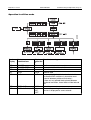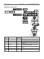
1
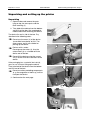
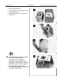
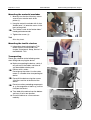
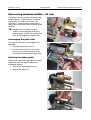
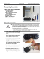
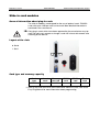
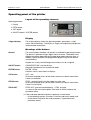
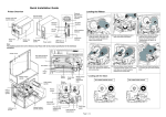
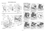
04/02 Rev. 2.14-01
USER MANUAL
TTK - Texxtile
Commissioning and Operation, Page 1
Commissioning and Operation
Unpacking and setting up the printer ............. 2
Unpacking ................................................. 2
Mounting the material unwinder................. 4
Mounting the textile stacker ....................... 4
Transporting .............................................. 4
Processing material widths > 52 mm............. 5
Exchanging the print roller ......................... 5
Refitting the ribbon guide........................... 5
Connecting the printer ................................... 6
Layout of the device connections............... 6
Mains cable connection ............................. 6
Connecting the data cable ......................... 7
Slide-in card modules.................................... 9
General information about plug-in cards .... 9
Layout of the slots ..................................... 9
Card type and memory capacity ................ 9
Operating panel of the printer ...................... 10
Layout of the operating elements ............. 10
Display..................................................... 10
Meanings of the buttons........................... 10
Operating modes......................................... 11
Off-line mode ........................................... 11
On-line mode ........................................... 11
Report status ........................................... 11
Basic operating procedures ......................... 12
Starting the printer ................................... 12
Restarting the printer (reset) .................... 12
Calling up the firmware version................ 12
Operation in off-line mode........................ 13
Operation in on-line mode........................ 14
Error messages ........................................... 15
Index ........................................................... 16
04/02 Rev. 2.14-01
USER MANUAL
TTK - Texxtile
Commissioning and Operation, Page 2
Unpacking and setting up the printer
Unpacking
1. Open the box and remove the parts
lying on top, the extra parts and the
foam covering (1).
1
2. Take hold of the device from the bottom
and lift it out the box. Get somebody to
hold the box when removing the device.
The device lies on its side in the box. Pay
attention to the following notes:
¯ Do not use the cover (2) of the device
(accessible from above) to lift it. The
cover moves and is not suitable for
picking up the device.
¯ Devices with a cutter:
2
3
Do not grasp the cutter (3). Use the
cutter motor (4) as a handle to lift the
device out of the box.
¯ Do not lift the device using the narrow
slit (5) of the card slot at the back of the
device.
If the packaging has a material inlet slot (6),
you can use it to start lifting up the device.
Then take hold of the device from the bottom
and lift it out of the box.
¯ Do not use other protruding components
(e. g. the magazine or label tray) to lift or
transport the device.
P Continued on the next page.
4
6
5
04/02 Rev. 2.14-01
USER MANUAL
TTK - Texxtile
3. Put the device down (1).
1
4. Turn the device to the position in which
it is to be used (2).
5. Place the device on a firm and level
surface (3).
2
3
¯ The packaging material (4) should be
stored for possible shipping.
Pay attention to environmental
protection if the packaging is to be
disposed of. Check whether it would be
possible to return it to your supplier.
P More detailed information about
environmental protection is contained in
the section "Safety Notes".
4
Commissioning and Operation, Page 3
04/02 Rev. 2.14-01
USER MANUAL
TTK - Texxtile
Commissioning and Operation, Page 4
Mounting the material unwinder
1. Manually turn the four Allan key screws
several turns into the back of the
printer (1).
2. Hang the material unwinder with its four
"button holes” (2) onto the screws in the
back of the printer.
¯ The "thicker” ends of the "button holes”
hereby point downwards.
2
2
2
1
1
1
1
2
3. Tighten the screws (3).
Tool
Allan key size 3
Mounting the textile stacker
P Information about attaching the TCS
textile stacker can be found in the
chapter "Attachment, Setup, Service" in
the MANUAL TCS.
Transporting
Please pay attention to the following notes
when lifting and carrying the device:
£ Before transporting the device, switch it
off, pull out all the cables and take off
any detachable exterior parts.
¯ Devices with a cutter:
Do not grasp the cutter. Use the cutter
motor as a handle when transporting the
device.
¯ Do not lift the device using the narrow
slit of the card slot at the back of the
device.
¯ Do not use other protruding components
(e. g. the magazine or label tray) to lift or
transport the device.
£ Take hold of the device from the bottom
and carry it to its new location.
£ Place the device on a firm and even
underlay.
3
04/02 Rev. 2.14-01
USER MANUAL
TTK - Texxtile
Commissioning and Operation, Page 5
Processing material widths > 52 mm
TTK printers are set ex works for processing
textile materials. Textile material cannot be
processed if it is wider than 52 mm. This
restriction is a constructional factor which is
due to the narrower print roller used for textile
material.
¯ Cardboard or self-adhesive label
material can although be used with a
width of above 52 mm, if the textile print
roller is exchanged for a special one.
1
Exchanging the print roller
Change the print roller as described in the
following:
1. Unscrew the thumb screw (1).
2. Pull out the print roller (2). It may be
necessary to switch the printer on to
raise the print head from the print roller.
2
Refitting the ribbon guide
Remove the sleeve from the ribbon transport
roller before processing self-adhesive or
cardboard material:
1. Strip off the red clamping ring (3).
2. Strip off the sleeve (4).
3
4
04/02 Rev. 2.14-01
USER MANUAL
TTK - Texxtile
Commissioning and Operation, Page 6
Connecting the printer
Layout of the device connections
1 Centronics interface
(parallel interface)
2 Serial interface RS232/RS485
(serial interface)
3 Recess for optional socket
4 Earthing screw
5 Mains cable connection
6 Mains switch
7 Fuse selector switch
1
2
5
6
7
3
4
Mains cable connection
¯ Before connecting the device to the mains power supply, it is necessary to
check the mains voltage setting on the device. Dangerous contact voltage
can arise if the device is connected to the mains power supply when setting
the mains voltage on the device fuse.
Therefore, pay attention to the following:
– Never alter the mains voltage setting or change the fuse when the
device is connected to the mains power supply!
1. Check whether the device voltage (10)
corresponds to the local mains voltage
rating.
11
Normally the device is already set to the
mains voltage rating of the destination
country before leaving the factory.
10
2. In order to set the mains voltage rating,
remove the insert (11) with a
screwdriver (12) and fit a suitable fuse
(13). Remove the insert (14) and turn it
so that the mains voltage rating (15) is
still visible in the slot window (10) after
the device has been installed.
12
P Information about suitable fuses can be
found in the chapter "Specifications" in
the section "Connector, device data".
3. Ensure that the mains switch (6) is
switched off, attach the mains cable to
the connector (5), and plug the mains
plug into the main power supply socket.
13
15
11
14
04/02 Rev. 2.14-01
USER MANUAL
TTK - Texxtile
Commissioning and Operation, Page 7
Connecting the data cable
¯ Switch off the device before plugging in or removing the data cable, the
mains power supply cable or the optional connector cable!
It is only permitted to connect devices to the interfaces or the sockets which
have been tested according to IEC 950 or VDE 0805, and which fulfil these
requirements in line with SELV.
Pay attention to these instructions to avoid damage to the device.
Standard
A serial interface V.24/DB25 (RS232) and parallel interface (Centronics)
are integrated as standard interfaces for connecting the printer. The parallel
interface is the default printer setting. The serial interface can be activated
in the parameter menu of the printer.
P You can find a summary of all the parameters and settings in the chapter
"Info Print-outs and Parameters".
RS422/RS485
As an option the manufacturer can replace the RS232 interface with an
RS422/RS485 interface. The RS232 interface is then no longer available!
P Information about upgrading from RS232 to RS422/RS485 can be found in
the Service Manual in the chapter "Service", section "Connections and
electrics".
• Connecting the printer to the PC:
£ Connect the data cable to the serial interface of the PC and – depending on
the data transmission to be used – to the serial or parallel connector socket
of the printer.
• Setting the printer to serial data transmission:
1. Connect and switch on the printer:
Display OFF
2. Press FEED+CUT button:
Display INFO
3. Press CUT button repeatedly until:
Display IFAC
4. Press ENTER button:
Display PORT
P Continued on the next page.
04/02 Rev. 2.14-01
USER MANUAL
TTK - Texxtile
5. Press ENTER button:
Display CENT
6. Press CUT button:
Display RS23
7. Press ENTER button:
Display PORT
8. Press FEED+CUT button:
Display IFAC
9. Press FEED+CUT button:
Display OFF
Commissioning and Operation, Page 8
04/02 Rev. 2.14-01
USER MANUAL
TTK - Texxtile
Commissioning and Operation, Page 9
Slide-in card modules
General information about plug-in cards
The slide-in modules are designed for the use of optional cards. PCMCIA
cards with up to 2 MB per card can be used. More detailed information is
contained in the card manual.
¯ Only plug-in cards which have been approved by the manufacturer may be
used. Do not insert, remove or change a card until at least 60 seconds after
switching off the device!
Layout of the slots
0 Slot 0
1 Slot 1
1
0
Card type and memory capacity
Card
type
PCMCIA
No. of
cards
2
Memory
per card
2 MB
PROM
card
–
SRAM
card
Flash
card
ê
ê
P Refer to the card manual for more information about the cards; refer to the
Easy Plug Manual for more information about programming.
04/02 Rev. 2.14-01
USER MANUAL
TTK - Texxtile
Commissioning and Operation, Page 10
Operating panel of the printer
Layout of the operating elements
Operating element:
1 Display
1
2
4
3
2 FEED button
3 CUT button
4 ON/OFF button (= ENTER button)
Display
4-figure display
The 4-figure display shows the operating modes, parameters, values,
status and malfunctions. The display is largely self-explanatory despite the
limited number of positions.
Meanings of the buttons
General
The small number of buttons still permits a multitude of operating functions.
The device is operated using a logical menu structure. The buttons have
different meanings depending on the operating mode and menu item. In
addition, special functions are programmed by pressing several buttons
simultaneously.
Despite this variety, the following main functions can be assigned:
ON/OFF button
ONLINE/OFFLINE =on-line/off-line:
Alternates between on-line and off-line mode
ENTER button
ENTER = Enter:
Confirms values, menu items or displays
CUT button
CUT = cut.
Also leads to deeper levels of the menu structure or selects menu items.
Values are reduced.
FEED button
FEED = material feed, in on-line mode start after stop.
Also leads to deeper levels of the menu structure or selects menu items.
Values are increased.
FEED+CUT
FEED+CUT (pressed simultaneously) = ESC (escape),
i.e. return to the main menu option. Also leads in off-line mode to the
parameter menu.
P Other and more detailed function assignments can be found
– in the following sections (Functions in off-line and on-line mode) and
– in the section "Info print-outs and parameters" (Operation of the
parameter menu).
04/02 Rev. 2.14-01
USER MANUAL
TTK - Texxtile
Commissioning and Operation, Page 11
Operating modes
Off-line mode
Display OFF
Off-line mode is for parameter settings, status reports and printer settings.
The printer is not ready to receive data via the selected interface (off-line).
Print jobs are not carried out.
£ Press the ON/OFF button in order to go into on-line mode.
On-line mode
Display ON
The on-line mode is usually activated after the printer has been switched on
(adjustable). The printer is ready for operation in the on-line mode. Data
can be received via the selected interface (on-line). Print jobs are carried
out. If the printer stops or an error occurs, the printer goes automatically
into off-line mode.
£ Press the ON/OFF button in order to go into on-line mode.
Report status
Status report
A malfunction or certain conditions are signalised by the printer with a
status report. In this report status, the printer waits for the error to be
corrected and/or an acknowledgement. After acknowledgement, the printer
goes from the report status into off-line mode (depending on the error and
how the previous process has been completed).
£ Acknowledge with the ENTER button and switch off the acoustic signal with
the FEED button in order to exit the report status (change to off-line).
04/02 Rev. 2.14-01
USER MANUAL
TTK - Texxtile
Commissioning and Operation, Page 12
Basic operating procedures
Starting the printer
1. Connect the printer to the mains power supply and plug in the interface
cable (if required).
2. Switch on the printer using the mains switch.
Display: xHxx
Version no. of the firmware, e.g. 1H20 for
11.8 Dot printers; xSxx for 8.0 Dot printers.
INIT
Drucker is being initialised.
ON
On-line mode is the default setting after
switching on; If OFF is displayed: Press
ON/OFF button to get to the Off-line mode.
The printer is now ready to receive data via the selected interface.
Restarting the printer (reset)
Display: Arbitrary (not off!)
Reset
£ Press the FEED+CUT+ON/OFF button (all 3 buttons simultaneously) in
order to reset the printer. The printer is restarted.
Display: same as under "Starting the printer".
The printer can therefore be restarted without having to switch the device
off first.
¯ During reset, all the data stored in the printer is deleted!
Calling up the firmware version
The firmware version (e.g. 1H34) is displayed during the reset procedure.
Reset
£ Press the FEED+CUT+ON/OFF button (all 3 buttons simultaneously) and
keep them pressed in order to see the version number! The printer is reset
and restarted.
Display: same as under "Starting the printer".
¯ During reset, all the data stored in the printer is deleted!
P For detailed description of the different firmware designations, refer to the
Service Manual, topic section "Firmware", paragraph "Firmware Versions".
04/02 Rev. 2.14-01
USER MANUAL
TTK - Texxtile
Commissioning and Operation, Page 13
Operation in off-line mode
Previous Button
display
combinations
OFF
OFF
OFF
OFF
OFF
OFF
OFF
Display
Function/meaning
afterward
s
ON/OFF
ON
On-line mode, printer is ready to receive
ON/OFF+FEED
<--Slow material and ribbon feed
ON/OFF+CUT
Cut, followed by reverse feed
FEED
FEED
Material feed
CUT
CUT
Cut (only if cutter installed and activated with
parameter KNIF and there is placed no uncut
material between printhead and cutter.)
If there are any printed labels placed between
printhead and cutter, those labels will be fed and
cut.
FEED+CUT
INFO
Selection parameter menu
FEED+CUT+ON/OFF xHxx,
Reset, after pressing the buttons, the firmware
version is displayed for some seconds.
INIT,
OFF
04/02 Rev. 2.14-01
USER MANUAL
TTK - Texxtile
Commissioning and Operation, Page 14
Operation in on-line mode
Previous Button combination Display
Function/meaning
display
afterwards
ON
FEED+CUT
HVxx
Print head power setting: increase value with
FEED button, decrease value with CUT button
WAIT
not possible
WAIT
Creation of print image
xxxx
Display of labels to be printed, including those
being printed
xxxx
ON/OFF
STOP
The label currently being printed is completed,
the display then starts to blink.
STOP
ON/OFF
OFF
Change into off-line-mode (quantity remains the
xxxx
same)
OFF
ON/OFF
STOP xxxx On-line mode with halted print job
STOP
FEED
xxxx
Restart print job
xxxx
04/02 Rev. 2.14-01
USER MANUAL
TTK - Texxtile
Commissioning and Operation, Page 15
Error messages
Previous Button
display
combinations
STxx
ON/OFF
FEED
CUT
STxx
(self-acknowledging)
Display
Function/meaning
afterwards
Status report STxx (xx = error number). Confirm
that the error has been corrected
(acknowledgement).
Switch off acoustic signal.
To exit the report status. Depending on the error,
either change into off-line mode or the previous
operation is continued.
xxxx
Status report as a warning, self-acknowledging.
The message appears for approx. 2 seconds on
the display. The printer then continues with its
previous job.
04/02 Rev. 2.14-01
USER MANUAL
TTK - Texxtile
Commissioning and Operation, Page 16
Index
B
Buttons, meanings.................................... 10
C
Centronics interface.................................... 6
Changing the fuse ...................................... 6
Checking the mains voltage........................ 6
Connecting the data cable .......................... 7
Connector cable, optional ........................... 7
Contact roller, exchanging.......................... 5
Contact voltage .......................................... 6
D
Device connections .................................... 6
Display ..................................................... 10
E
Earthing screw............................................ 6
Error messages ........................................ 15
F
Firmware version, display ......................... 12
Fuse selector switch ................................... 6
I
Interface cable............................................ 7
Interfaces ................................................... 7
L
LCLR .......................................................... 9
M
Mains cable connection .............................. 6
Mains switch............................................... 6
Mains voltage setting.................................. 6
Materials wider than 52 mm........................ 5
Memory capacity ........................................ 9
Mounting the material unwinder.................. 4
Mounting the textile stacker ........................ 4
O
Off-line mode ............................................11
Off-line mode, operation ...........................13
On-line mode ............................................11
On-line mode, operation ...........................14
Operating elements, layout .......................10
Operating modes ......................................11
Operating panel ........................................10
Operating procedures ...............................12
Optional socket...........................................6
P
Packaging material .....................................3
Plug-in card ................................................9
Plug-in cards...............................................9
R
Refitting the ribbon guide ............................5
Report status ............................................11
Reset ........................................................12
Restart......................................................12
RS232-interface..........................................7
S
Serial data transmission, setting .................7
Serial interface............................................6
Serial interface, exchanging........................7
Setting up, printer .......................................2
Slide-in card module ...................................9
Slots, layout ................................................9
Starting the printer ....................................12
T
TCS ............................................................4
U
Unpacking, printer.......................................2
Unwinder, mounting....................................4