1
Center for Embedded Computer Systems
University of California, Irvine
User Manual for Embedded System Environment
ESE Version 2.0.0
Daniel D. Gajski, Samar Abdi, Gunar Schirner, Han-su Cho, Yonghyun
Hwang, Lochi Yu, Ines Viskic and Quoc-Viet Dang
Technical Report CECS-08-14
December 12, 2008
.
Center for Embedded Computer Systems
University of California, Irvine
Irvine, CA 92697-2620, USA
(949) 824-8919
.
{gajski, sabdi, hschirne, hscho, yonghyuh, lochi.yu, iviskic,
qpdang}@uci.edu
http://www.cecs.uci.edu/~ese
User Manual for Embedded System Environment:
ESE Version 2.0.0
Copyright © 2008 CECS, UC Irvine
User Manual for Embedded System Environment:
ESE Version 2.0.0
Table of Contents
1. Introduction................................................................................................................ 1
2. Usage ........................................................................................................................... 3
2.1. Manual Conventions .........................................................................................3
2.2. Starting ESE......................................................................................................4
2.2.1. Scripting.................................................................................................4
2.2.2. Environment Variables ...........................................................................5
3. Main Window ............................................................................................................. 7
3.1. Menu Bar ..........................................................................................................8
3.1.1. File Menu ...............................................................................................8
3.1.2. Edit Menu...............................................................................................9
3.1.3. View Menu...........................................................................................10
3.1.4. Synthesis Menu....................................................................................10
3.1.5. Validation Menu...................................................................................11
3.1.6. Windows Menu ....................................................................................11
3.1.7. Help......................................................................................................12
3.2. Design Canvas.................................................................................................12
3.3. PE Window .....................................................................................................13
3.3.1. PE Window Processes..........................................................................14
3.3.2. PE Window Memories .........................................................................17
3.3.3. PE Window Channels ..........................................................................19
3.4. Channel Window.............................................................................................21
3.4.1. Channel Window Process Channels.....................................................22
3.4.2. Channel Window Memory Channels ...................................................23
3.4.3. Channel Window FIFO Channels ........................................................23
3.5. Database Window ...........................................................................................24
3.6. Output Window...............................................................................................25
3.7. Message Boxes................................................................................................26
3.7.1. Error Dialogs........................................................................................26
3.7.2. Information Dialogs .............................................................................27
4. Functionality............................................................................................................. 29
4.1. Application Preferences ..................................................................................29
4.1.1. Application Preferences .......................................................................29
4.2. Design Handling .............................................................................................32
4.2.1. Design Creation ...................................................................................34
4.2.2. Design Opening ...................................................................................34
4.2.3. Design Saving ......................................................................................36
4.2.4. Design Reloading.................................................................................37
4.2.5. Design Closing.....................................................................................37
© 2008, CECS
iii
User Manual for Embedded System Environment:
ESE Version 2.0.0
4.2.6. Design Exporting .................................................................................38
4.2.7. Design Settings Editing .......................................................................39
4.2.8. Design Source Viewing........................................................................40
4.2.9. ESE Exiting..........................................................................................41
4.3. Transaction Level Modeling ...........................................................................41
4.3.1. PE Allocation .......................................................................................42
4.3.2. PE Mapping .........................................................................................45
4.3.3. Network Allocation..............................................................................49
4.3.4. Channel Mapping.................................................................................58
4.4. TLM Synthesis................................................................................................63
4.4.1. Generate Functional TLM....................................................................64
4.4.2. Generate TLM......................................................................................64
4.5. TLM Validation...............................................................................................64
4.5.1. Simulate Functional TLM....................................................................64
4.5.2. Simulate Timed TLM...........................................................................64
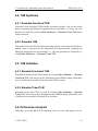
4.6. Performance Analysis .....................................................................................64
4.6.1. PE Performance Analysis ....................................................................65
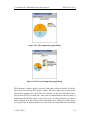
4.6.2. Bus Performance Analysis...................................................................67
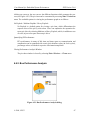
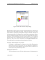
4.6.3. CE Performance Analysis ....................................................................69
4.7. Window Management .....................................................................................69
5. Data Modeling ..........................................................................................................72
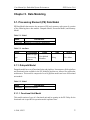
5.1. Processing Element (PE) Data Model.............................................................72
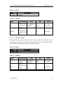
5.1.1. Datapath Model....................................................................................72
5.1.2. Execution Model ..................................................................................75
5.1.3. Memory Model ....................................................................................78
5.2. Bus Model.......................................................................................................81
A. XML stylesheet for PE Data Model.......................................................................84
A.1. Data Type .......................................................................................................84
A.2. Elements.........................................................................................................84
B. XML stylesheet for Bus Models .............................................................................88
C. Example XMLs........................................................................................................89
C.1. Example XML for MicroBlaze ......................................................................89
C.2. Example XML for Custom Hardware ..........................................................105
C.3. Example XML for OPB ...............................................................................113
© 2008, CECS
iv
User Manual for Embedded System Environment:
ESE Version 2.0.0
List of Tables
5-1. Model...................................................................................................................... 72
5-2. Attribute.................................................................................................................. 72
5-3. Model...................................................................................................................... 72
5-4. Model...................................................................................................................... 72
5-5. Attribute.................................................................................................................. 73
5-6. Model...................................................................................................................... 73
5-7. Attribute.................................................................................................................. 73
5-8. Model...................................................................................................................... 74
5-9. Attribute.................................................................................................................. 74
5-10. Model.................................................................................................................... 74
5-11. Attribute................................................................................................................ 75
5-12. Model.................................................................................................................... 75
5-13. Attribute................................................................................................................ 75
5-14. Model.................................................................................................................... 76
5-15. Attribute................................................................................................................ 76
5-16. Model.................................................................................................................... 76
5-17. Attribute................................................................................................................ 77
5-18. Model.................................................................................................................... 77
5-19. Attribute................................................................................................................ 77
5-20. Model.................................................................................................................... 78
5-21. Attribute................................................................................................................ 78
5-22. Model.................................................................................................................... 78
5-23. Model.................................................................................................................... 78
5-24. Attribute................................................................................................................ 79
5-25. Model.................................................................................................................... 79
5-26. Attribute................................................................................................................ 79
5-27. Model.................................................................................................................... 80
5-28. Attribute................................................................................................................ 80
5-29. Model.................................................................................................................... 80
5-30. Attribute................................................................................................................ 80
5-31. Attribute................................................................................................................ 81
List of Figures
1-1. User Manual for Embedded System Environment. ..................................................1
3-1. Main Window of ESE...............................................................................................7
3-2. Design Canvas. .......................................................................................................13
© 2008, CECS
v
User Manual for Embedded System Environment:
ESE Version 2.0.0
3-3. PE Window. ............................................................................................................ 14
3-4. Channel Window.....................................................................................................21
3-5. Database Window. ..................................................................................................25
3-6. Output Window.......................................................................................................25
3-7. Error dialog............................................................................................................. 27
3-8. Information dialog. .................................................................................................27
4-1. Edit Preferences dialog...........................................................................................30
4-2. Database Selection dialog.......................................................................................30
4-3. SystemC Path Selection dialog...............................................................................31
4-4. Design Open dialog. ...............................................................................................35
4-5. Design Save dialog. ................................................................................................36
4-6. Design Export dialog. .............................................................................................38
4-7. Design Settings (TLM Compiler tab) dialog. .........................................................39
4-8. Design Source Viewing dialog. ..............................................................................40
4-9. PE Allocation result................................................................................................43
4-10. PE Parameters dialog............................................................................................43
4-11. Process Renaming dialog......................................................................................46
4-12. Adding Sources to a Process (C File) dialog........................................................46
4-13. Adding Sources to a Process (C File) dialog........................................................47
4-14. Adding a Process Port to a Process dialog. ..........................................................48
4-15. Bus Allocation result. ...........................................................................................50
4-16. Bus Parameters dialog. .........................................................................................51
4-17. Bus Addressing dialog..........................................................................................52
4-18. Bus Synchronization dialog..................................................................................52
4-19. CE Allocation result. ............................................................................................54
4-20. CE Parameters dialog. ..........................................................................................55
4-21. CE Scheduling dialog. ..........................................................................................55
4-22. Port Adding dialog................................................................................................57
4-23. Connecting to the bus dialog. ...............................................................................58
4-24. Add Channel context menu. .................................................................................58
4-25. Process-to-Process Channel dialog.......................................................................59
4-26. Memory Channel dialog. ......................................................................................60
4-27. FIFO Channel dialog. ...........................................................................................62
4-28. PE Performance Analysis dialog. .........................................................................65
4-29. PE Computation graph dialog...............................................................................65
4-30. Process Computation graph dialog. ......................................................................66
4-31. Bus Performance Analysis dialog.........................................................................67
4-32. Bus Data Transfer Analysis dialog. ......................................................................68
© 2008, CECS
vi
User Manual for Embedded System Environment:
ESE Version 2.0.0
Chapter 1. Introduction
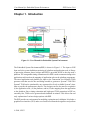
Figure 1-1. User Manual for Embedded System Environment.
The Embedded System Environment(ESE) is shown in Figure 1-1. The input to ESE
front-end is the system definition consisting of a platform and application code. A library
of processing elements, buses, bridges and RTOS is provided in ESE to develop such a
platform. The retargetable timing estimation tool in ESE is used to annotate timing to the
application code based on the mapping of application code on the platform components.
The timed application and platform are input to the Transaction Level Model (TLM)
generator tool that uses the bus and bridge models to generate a SystemC TLM. This
SystemC TLM can be simulated by any commercial or freely available SystemC simulator to provide the performance metrics. The designer can use the metrics to optimize
(i) the application code, (ii) the platform, and/or (iii) the mapping from the application
to the platform. Since timing estimation and high-speed TLM generation in ESE are
extremely fast, TLMs can be generated and simulated in minutes. This allows fast and
early exploration of various design options with ESE.
The ESE provides an environment for modeling, estimation and validation. It includes a
graphical user interface (GUI) and a set of tools to facilitate the design flow and perform
© 2008, CECS
1
User Manual for Embedded System Environment:
ESE Version 2.0.0
the aforementioned optimization steps. The two major components of the GUI are the
Design Decision Interface (DDI) and the Validation User Interface (VUI). The DDI
allows designers to make and input design decisions, such as allocation of HW and
SW components in the platform, and the mapping of application to the platform. With
design decisions made, TLM generation and estimation tools can be invoked to generate
functional and timed TLMs. The VUI allows the simulation of all TLMs using the OSCI
SystemC simulator to validate the design at each stage of the design flow.
With the assistance of the GUI and automatic TLM generation tools, it is relatively easy
for designer to step through the design process. With the editing, browsing and algorithm
selection capability provided by the GUI, the C application processes can be efficiently
captured by designers. Communication channels between the application processes can
be created using an intuitive channel wizard. The HW platform can be allocated easily
by simple drag-drop of components from the database. The processing elements(PEs),
bridges and buses can be connected using ports. The mapping of the procesess to PEs
and channels to buses/routes can also be done easily in the GUI. The TLM generation
tools can be used to verify both the functional correctness of the design and to accurately
estimate the performance. Various statistics are generated automatically by the tied TLM
simulation. These statistics can be viewed graphically using the GUI.
© 2008, CECS
2
User Manual for Embedded System Environment:
ESE Version 2.0.0
Chapter 2. Usage
In the following sections, the general usage of the ESE application will be outlined.
Followed by a description of basic formatting conventions used throughout the manual,
information pertinent to running the ESE application will be provided.
2.1. Manual Conventions
The following style and formatting conventions are used throughout the text of this manual to refer to commands, actions, or GUI elements:
Command
Refers to a command or other data input typed in and entered by the user.
Message
Refers to a log or other text message produced by the ESE application on the screen.
Key
Refers to a key that a user can press on the keyboard.
Label
Refers to a button, menu or any other general label in the GUI of the ESE main
application.
Win::Sub
Refers to a sub-item inside one of the parts of the ESE application main window.
Win refers to one of the following parts of the application main window (see
Chapter 3 Main Window (page 7)):
•
Main represents the Main Window itself (i.e. its menu or tool bar).
•
Project represents the Project Window.
•
Output represents the Output Window.
•
Design represents the Design Window.
Sub refers to drop-down menus or sub windows (tabs):
© 2008, CECS
3
User Manual for Embedded System Environment:
ESE Version 2.0.0
•
For the Main Window, Sub is either File, View, Project, Synthesis, or Windows (drop-down menus introduced in Section 3.1 Menu Bar (page 8)).
•
For the Project Window, Sub is either Models, Imports, or Sources (tabs introduced in.
•
For the Output Window, Sub is either Compile or Refine (tabs introduced in.
•
For the Design Window, Sub is either Hierarchy, Behaviors, or Channels
(sidebar tabs introduced.
For example, Project::Models refers to the models tab in the Project Window.
Menu−→Command
Refers to a main menu or context menu command (described in) where Command
refers to the menu command and Menu refers to a main menu entry or to a context
menu in a named subwindow (tab).
For example, Main::File−→Open... refers to the Open... command
in the File menu of the Main Window menu bar. On the other hand,
Project::Models−→Open refers to the Open command in the context menu of
the Project Window Models tab.
2.2. Starting ESE
ESE is invoked by entering
% ese
at the command line prompt (%). This will start the application and open the main window (Chapter 3 Main Window (page 7)) of the combined SCE graphical user interface
(GUI).
2.2.1. Scripting
ESE supports scripting of the complete environment from the command line without the
need to invoke the GUI. For scripting purposes, a GUI-less command shell of ESE can
© 2008, CECS
4
User Manual for Embedded System Environment:
ESE Version 2.0.0
be invoked by entering
% scsh
at the command line prompt (%). This will start the ESE shell without the GUI layer.
Instead, a prompt (>>) is offered to enter commands that allow to drive the ESE environment interactively (or from ESE shell scripts read from files supplied on the scsh
command line).
The ESE shell is based on an embedded Python interpreter. As such, it conforms to
Python syntax and the full semantics of the Python language is available. In addition,
the ESE shell extends the Python interpreter with an API for access to ESE functionality. However, the ESE shell API only provides undocument low-level access to ESE
internals for developers.
For user-level scripting of ESE by designers, a complete set of high-level scripts on top
of the ESE shell are available. The set of scripts provides a convenient command-line
interface for all necessary ESE functionality . Together with command-line interfaces
to model refinement tools and to the SpecC compiler , complete scripting of the ESE
design flow from the command line, through shell scripts or via Makefiles is possible.
2.2.2. Environment Variables
HOME
Determines the location of the user’s home directory and consequently the default
path to the file with user-specific application preferences ($HOME/.ese/eserc).
ESERC_PATH
Determines the list of directories where files serrc with user-specific application
preferences are stored. Multiple directories can be provided, separated by colons
(“:”). Directories are searched for and preference files are read in the given order,
i.e. preference files in later directories can override settings in earlier ones. Modified
preferences will be written to the first directory in the list that is writeable by the
user.
If ESERC_PATH is not set, the location (directory) of the user-specific serrc file
defaults to $HOME/.ese.
© 2008, CECS
5
User Manual for Embedded System Environment:
© 2008, CECS
ESE Version 2.0.0
6
User Manual for Embedded System Environment:
ESE Version 2.0.0
Chapter 3. Main Window
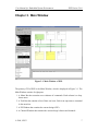
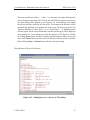
Figure 3-1. Main Window of ESE.
The primary GUI of ESE is the Main Window, which is displayed in Figure 3-1. The
Main Window consists of eight parts:
1. A Menu Bar that contains seven columns of commands. Each column is a dropdown menu.
2. A Tool Bar that contains a list of short-cut icons. Each icon represents a command
in the menu bar.
3. A PE Window that contains the current design’s PE’s.
4. A Channel Window that contains the current design’s busses and channels.
© 2008, CECS
7
User Manual for Embedded System Environment:
ESE Version 2.0.0
5. A Database Window that contains the current database’s available components.
6. A Design Canvas that contains the graphical representations of the objects of the
current design.
7. An Output Window.
8. A Status Bar that displays the current status of ESE, such as Loading... or Ready.
In this section, we introduce organization-related and display-related details of Menu
Bar, PE Window, Channel Window, Database Window, Design Canvas, and Output Window. Some windows contain drop-down menus or pop-up menus. The menus further
contain design commands. The usage and functionality behind the commands will be
described later.
3.1. Menu Bar
The Menu Bar contains seven main menu entries: File, Edit, View, Synthesis, Validation, Windows, and Help. Each main menu entry is a drop-down menu which contains
a number of commands. In general, unless otherwise noted, selecting a main menu entry
will apply the corresponding action to the currently active design, i.e. to the design that
is currently open. If there is no currently active design, menu commands will silently
fail (do nothing).
3.1.1. File Menu
The File menu contains ten commands:
File−→New...
Selecting
New...
will
create
Section 4.2.1 Design Creation (page 34)).
a
new
design
file
(see
File−→Open...
Selecting Open... will allow loading and opening of an existing design file (see
Section 4.2.2 Design Opening (page 34)).
© 2008, CECS
8
User Manual for Embedded System Environment:
ESE Version 2.0.0
File−→Close
Selecting
Close
will
close
Section 4.2.5 Design Closing (page 37)).
the
current
design
(see
File−→Reload
Selecting Reload will trigger reloading of the current design file from disk (e.g.
in case the file has changed on disk or reverting to the last saved version) (see
Section 4.2.4 Design Reloading (page 37)).
File−→Save
Selecting
Save
will
save
the
Section 4.2.3 Design Saving (page 36)).
current
design
file
(see
File−→Save As...
Selecting Save As... will save the current design file as a another file (see
Section 4.2.3 Design Saving (page 36)).
File−→Export...
Selecting Export... will allow saving and exporting of the current design in a compressed file format (see Section 4.2.6 Design Exporting (page 38)).
File−→Settings...
Selecting Settings... will display the settings of the current design file (see
Section 4.2.7 Design Settings Editing (page 39)).
File−→Exit
Selecting
Exit
will
exit
Section 4.2.9 ESE Exiting (page 41)).
© 2008, CECS
from
and
quit
ESE
(see
9
User Manual for Embedded System Environment:
ESE Version 2.0.0
3.1.2. Edit Menu
The Edit menu contains one command:
Edit−→Preferences...
Selecting Preferences... will allow viewing and modifying of application preferences (see Section 4.1 Application Preferences (page 29)).
3.1.3. View Menu
The View menu contains three commands:
View−→Source...
Selecting Source... will allow viewing of the source file of the current design (see
Section 4.2.8 Design Source Viewing (page 40)).
View−→Chart...
Selecting Chart... will display the chart of the current design.
View−→Connectivity...
Selecting Connectivity... will display the connectivity chart of the current design.
3.1.4. Synthesis Menu
The Synthesis menu contains five commands:
Synthesis−→Generate Functional TLM...
Selecting Generate Functional TLM... generates the functional tlm for the current
design (see Section 4.4.1 Generate Functional TLM (page 64)).
Synthesis−→Generate Timed TLM...
Selecting Generate Timed TLM... generates the timed tlm for the current design
(see Section 4.4.2 Generate TLM (page 64)).
© 2008, CECS
10
User Manual for Embedded System Environment:
ESE Version 2.0.0
Synthesis−→Select Board...
Selecting Select Board... presents a sub-menu, which allows selection of the board
to which the current design can be synthesized.
Synthesis−→Synthesize to Board...
Selecting Synthesize to Board... synthesizes the current design onto the selected
board.
Synthesis−→Stop
Selecting Stop stops any running generation and synthesizing processes for the
current design.
3.1.5. Validation Menu
The Validation menu contains four commands:
Validation−→Simulate Functional TLM...
Selecting Simulate Functional TLM... simulates the functional tlm for the current
design (see Section 4.5.1 Simulate Functional TLM (page 64)).
Validation−→Simulate Timed TLM...
Selecting Simulate Timed TLM... simulates the timed tlm for the current design
(see Section 4.5.2 Simulate Timed TLM (page 64)).
Validation−→Kill Simulation...
Selecting Kill Simulation... presents a sub-menu allowing the selection of which
active simulation to terminate from the current design.
Validation−→View Log...
Selecting View Log... shows the log of the current design.
© 2008, CECS
11
User Manual for Embedded System Environment:
ESE Version 2.0.0
3.1.6. Windows Menu
The Windows menu contains two commands:
Windows−→Output Window
Selecting Output Window will display or undisplay the Output Window (see
Section 3.6 Output Window (page 25)).
Windows−→Toolbars
Selecting Toolbars presents a sub-menu allowing the selection of toolbar(s) to
show/hide.
3.1.7. Help
The Help menu contains two commands:
Help−→Manual...
Selecting Manual... will open the ESE user manual in the online help browser.
Help−→About...
Selecting About... will pop up a dialog with version and copyright information of
the ESE environment.
© 2008, CECS
12
User Manual for Embedded System Environment:
ESE Version 2.0.0
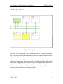
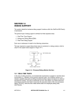
3.2. Design Canvas
Figure 3-2. Design Canvas.
The Design Canvas displays the content and the attributes of an opened design graphically, and it allows browsing and manipulating of the design objects. The Design Canvas
is displayed in Figure 3-2.
The canvas supports modifying the layout and attributes of the design via drag-and-drop
and through a context menu. Dragging objects from the Database Window adds an object
to the design. Dragging objects within the Design Canvas repositions the object accordingly. Deletion, renaming, adding and removing ports, as well as viewing properties are
accessed via the context menu and available dependent upon the type of object currently
selected (see Section 4.2 Design Handling (page 32)).
© 2008, CECS
13
User Manual for Embedded System Environment:
ESE Version 2.0.0
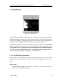
3.3. PE Window
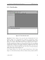
Figure 3-3. PE Window.
In the PE Window side bar, all the processes, source files, local memories and local
channels associated with each PE in the design are listed. Every PE is represented as
a tab in the PE Window. Unmapped processes, local memories, and local channels are
displayed in the Unmapped tab. The PE Window is displayed in Figure 3-3.
Each PE tab contains processes, local memories, and local channels. The Processes
category contains all processes for the PE. If available, each process displays associated Process Ports and Source Files. Internal Memories and Exposed Memories
are displayed under the Memories category. The Channels category displays the PE’s
Process Channels, Memory Channels and FIFO Channels.
3.3.1. PE Window Processes
Right-clicking on the Processes category in the PE Window opens a context-menu
pop-up for the selected processes. The context menu for Processes contains two commands:
Add Process
Selecting Add Process will add a new instance of the selected entity (see
Section 4.3.2 PE Mapping (page 45)).
© 2008, CECS
14
User Manual for Embedded System Environment:
ESE Version 2.0.0
Remove All Processes
Selecting Remove All Processes will remove all entities of the selected type (see
Section 4.3.2 PE Mapping (page 45)).
Right-clicking on a process under the Processes category in the PE Window opens
a context-menu pop-up for the selected process. The context menu for each process
contains eight commands:
Rename Process
Selecting Rename Process will
Section 4.3.2 PE Mapping (page 45)).
rename
the
selected
entity
(see
Add Process
Selecting Add Process will add a new instance of the selected entity (see
Section 4.3.2 PE Mapping (page 45)).
Remove Process(es)
Selecting Remove Process(es) will remove all entities of the selected type (see
Section 4.3.2 PE Mapping (page 45)).
Add .C File(s)
Selecting Add .C File(s) will add a new source file of the specified type (see
Section 4.3.2 PE Mapping (page 45)).
Add .H File(s)
Selecting Add .H File(s) will add a new source file of the specified type (see
Section 4.3.2 PE Mapping (page 45)).
Remove All Source File(s)
Selecting Remove All Source File(s) will remove all entities of the selected type
from the process (see Section 4.3.2 PE Mapping (page 45)).
Add Process Port
Selecting Add Process Port will add a new instance of the selected entity to the
process (see Section 4.3.2 PE Mapping (page 45)).
© 2008, CECS
15
User Manual for Embedded System Environment:
ESE Version 2.0.0
Remove All Process Port(s)
Selecting Remove All Process Port(s) will remove all entities of the selected
type from the process (see Section 4.3.2 PE Mapping (page 45)).
Right-clicking on Process Ports under a Process in the PE Window opens a contextmenu pop-up for the selected process ports. The context menu for Process Ports contains two commands:
Add Process Port
Selecting Add Process Port will add a new instance of the selected entity to the
process (see Section 4.3.2 PE Mapping (page 45)).
Remove All Process Port(s)
Selecting Remove All Process Port(s) will remove all entities of the selected
type from the process (see Section 4.3.2 PE Mapping (page 45)).
Right-clicking on a process port under Process Ports in the PE Window opens a
context-menu pop-up for the selected process class. The context menu for each process
port contains three commands:
Add Process Port
Selecting Add Process Port will add a new instance of the selected entity to the
process (see Section 4.3.2 PE Mapping (page 45)).
Remove Process Port(s)
Selecting Remove Process Port(s) will remove the selected entities of the selected type from the process (see Section 4.3.2 PE Mapping (page 45)).
Properties
Selecting Properties will open a properties dialog box the selected entity from the
process. The user is able to rename the function names for the entity in this dialog
box (see Section 4.3.2 PE Mapping (page 45)).
Right-clicking on Source Files under a process in the PE Window opens a contextmenu pop-up for the selected source files. The context menu for Source Files contains
three commands:
© 2008, CECS
16
User Manual for Embedded System Environment:
ESE Version 2.0.0
Add .C File(s)
Selecting Add .C File(s) will add a new source file of the specified type (see
Section 4.3.2 PE Mapping (page 45)).
Add .H File(s)
Selecting Add .H File(s) will add a new source file of the specified type (see
Section 4.3.2 PE Mapping (page 45)).
Remove All Source File(s)
Selecting Remove All Source File(s) will remove all entities of the selected type
from the process (see Section 4.3.2 PE Mapping (page 45)).
Right-clicking on a source file under Source Files in the PE Window opens a contextmenu pop-up for the selected source files. The context menu for each source file contains
four commands:
Add .C File(s)
Selecting Add .C File(s) will add a new source file of the specified type (see
Section 4.3.2 PE Mapping (page 45)).
Add .H File(s)
Selecting Add .H File(s) will add a new source file of the specified type (see
Section 4.3.2 PE Mapping (page 45)).
Remove File(s)
Selecting Remove File(s) will remove all selected entities of the selected type
from the process (see Section 4.3.2 PE Mapping (page 45)).
View Source
Selecting View Source will open the Design Viewer and show the source code
for the file (see Section 4.3.2 PE Mapping (page 45)).
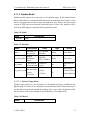
3.3.2. PE Window Memories
Right-clicking on the Memories category in the PE Window opens a context-menu
pop-up for the selected process class. The context menu for Memories contains three
commands:
© 2008, CECS
17
User Manual for Embedded System Environment:
ESE Version 2.0.0
Add Exposed Memory
Selecting Add Exposed Memory will add a new instance of the selected entity
(see Section 4.3.2 PE Mapping (page 45)).
Add Internal Memory
Selecting Add Internal Memory will add a new instance of the selected entity (see
Section 4.3.2 PE Mapping (page 45)).
Remove All Selected Memories
Selecting Remove All Selected Memories will remove all entities of the selected
type (see Section 4.3.2 PE Mapping (page 45)).
Right-clicking on the Exposed sub-category under the Memories category in the PE
Window opens a context-menu pop-up for the selected process class. The context menu
for Exposed contains two commands:
Add Exposed Memory
Selecting Add Exposed Memory will add a new instance of the selected entity
(see Section 4.3.2 PE Mapping (page 45)).
Remove All Exposed Memories
Selecting Remove All Exposed Memories will remove all entities of the selected
type (see Section 4.3.2 PE Mapping (page 45)).
Right-clicking on a memory under the Exposed sub-category in the PE Window opens
a context-menu pop-up for the selected process class. The context menu for Exposed
contains four commands:
Rename Memory
Selecting Rename Memory will allow the user to rename the selected entity (see
Section 4.3.2 PE Mapping (page 45)).
Add Exposed Memory
Selecting Add Exposed Memory will add a new instance of the selected entity
(see Section 4.3.2 PE Mapping (page 45)).
© 2008, CECS
18
User Manual for Embedded System Environment:
ESE Version 2.0.0
Remove Selected Memories
Selecting Remove Selected Memories will remove selected entities of the selected type from the process (see Section 4.3.2 PE Mapping (page 45)).
Set Memory Size
Selecting Set Memory Size will allow the user to set the size of the entity under
the Details column (see Section 4.3.2 PE Mapping (page 45)).
Right-clicking on the Internal sub-category under the Memories category in the PE
Window opens a context-menu pop-up for the selected process class. The context menu
for Internal contains two commands:
Add Internal Memory
Selecting Add Internal Memory will add a new instance of the selected entity (see
Section 4.3.2 PE Mapping (page 45)).
Remove All Internal Memories
Selecting Remove All Internal Memories will remove all entities of the selected
type (see Section 4.3.2 PE Mapping (page 45)).
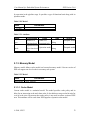
3.3.3. PE Window Channels
Right-clicking on the Channels category in the PE Window opens a context-menu popup for the selected channel class. The context menu for Channels contains one command:
Remove Selected Channels
Selecting Remove Selected Channels will remove all entities of the selected
type (see Section 4.3.2 PE Mapping (page 45)).
Right-clicking on the Process Channels sub-category under the Channels category in
the PE Window opens a context-menu pop-up for the selected channel class. The context
menu for Process Channels contains one command:
Remove Selected Channels
Selecting Remove Selected Channels will remove all entities of the selected
type (see Section 4.3.2 PE Mapping (page 45)).
© 2008, CECS
19
User Manual for Embedded System Environment:
ESE Version 2.0.0
Right-clicking on a channel under the Process Channels sub-category in the PE Window opens a context-menu pop-up for the selected channel class. The context menu for
Process Channels contains two commands:
Remove Channel(s)
Selecting Remove Channel(s) will remove all selected entities of type (see
Section 4.3.2 PE Mapping (page 45)).
Properties
Selecting Properties will open a properties dialog box for the selected entity from
the process. The user is able to modify port and route properties in this dialog box.
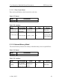
Right-clicking on the Memory Channels sub-category under the Channels category in
the PE Window opens a context-menu pop-up for the selected channel class. The context
menu for each channel contains one command:
Remove Selected Channels
Selecting Remove Selected Channels will remove all entities of the selected
type (see Section 4.3.2 PE Mapping (page 45)).
Right-clicking on a channel under the Memory Channels sub-category in the PE Window opens a context-menu pop-up for the selected channel class. The context menu for
each channel contains two commands:
Remove Channel(s)
Selecting Remove Channel(s) will remove all selected entities of type (see
Section 4.3.2 PE Mapping (page 45)).
Properties
Selecting Properties will open a properties dialog box for the selected entity from
the process. The user is able to modify port, address, and route properties in this
dialog box (see Section 4.3.2 PE Mapping (page 45)).
Right-clicking on the FIFO Channels sub-category under the Channels category in
the PE Window opens a context-menu pop-up for the selected channel class. The context
menu for FIFO Channels contains one command:
© 2008, CECS
20
User Manual for Embedded System Environment:
ESE Version 2.0.0
Remove Selected Channels
Selecting Remove Selected Channels will remove all entities of the selected
type (see Section 4.3.2 PE Mapping (page 45)).
Right-clicking on a channel under the FIFO Channels sub-category in the PE Window
opens a context-menu pop-up for the selected channel class. The context menu for each
channel contains two commands:
Remove Channel(s)
Selecting Remove Channel(s) will remove all selected entities of type (see
Section 4.3.2 PE Mapping (page 45)).
Properties
Selecting Properties will open a properties dialog box for the selected entity from
the process. The user is able to modify port, mapping, and route properties in this
dialog box.
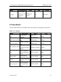
3.4. Channel Window
Figure 3-4. Channel Window.
© 2008, CECS
21
User Manual for Embedded System Environment:
ESE Version 2.0.0
In the Channel Window side bar, all the channels associated with each Bus and CE in
the design are listed. Every Bus and CE is represented as a tab in the Channel Window. Unmapped channels are displayed in the Unmapped tab. The Channel Window is
displayed in Figure 3-4.
Each Channel tab contains channels organized by channel categories: Process Channels, Memory Channels, and FIFO Channels.
3.4.1. Channel Window Process Channels
Right-clicking on the Process Channels category in the Channel Window opens a
context-menu pop-up for the selected channel class. The context menu for Process
Channels contains two commands:
Add Channel
Selecting Add Channel will open a dialog box for adding a channel. The
user is able to specify the new channel’s properties in this dialog box (see
Section 4.3.4 Channel Mapping (page 58)).
Remove All Process Channels
Selecting Remove All Process Channels will remove all entities of the selected
type from the tab (see Section 4.3.4 Channel Mapping (page 58)).
Right-clicking on a channel under the Process Channels category in the PE Window
opens a context-menu pop-up for the selected channel class. The context menu for Process Channels contains three commands:
Add Channel
Selecting Add Channel will open a dialog box for adding a channel. The
user is able to specify the new channel’s properties in this dialog box (see
Section 4.3.4 Channel Mapping (page 58)).
Remove Channel(s)
Selecting Remove Channel(s) will remove all selected entities of type (see
Section 4.3.4 Channel Mapping (page 58)).
© 2008, CECS
22
User Manual for Embedded System Environment:
ESE Version 2.0.0
Properties
Selecting Properties will open a properties dialog box for the selected entity from
the process. The user is able to modify port and route properties in this dialog box.
3.4.2. Channel Window Memory Channels
Right-clicking on the Memory Channels category in the Channel Window opens a
context-menu pop-up for the selected channel class. The context menu for Memory
Channels contains two commands:
Add Channel
Selecting Add Channel will open a dialog box for adding a channel. The
user is able to specify the new channel’s properties in this dialog box (see
Section 4.3.4 Channel Mapping (page 58)).
Remove All Memory Channels
Selecting Remove All Memory Channels will remove all entities of the selected
type from the tab (see Section 4.3.4 Channel Mapping (page 58)).
Right-clicking on a channel under the Memory Channels category in the PE Window
opens a context-menu pop-up for the selected channel class. The context menu for each
channel contains three commands:
Add Channel
Selecting Add Channel will open a dialog box for adding a channel. The
user is able to specify the new channel’s properties in this dialog box (see
Section 4.3.4 Channel Mapping (page 58)).
Remove Channel(s)
Selecting Remove Channel(s) will remove all selected entities of type (see
Section 4.3.4 Channel Mapping (page 58)).
Properties
Selecting Properties will open a properties dialog box for the selected entity from
the process. The user is able to modify port, address, and route properties in this
dialog box.
© 2008, CECS
23
User Manual for Embedded System Environment:
ESE Version 2.0.0
3.4.3. Channel Window FIFO Channels
Right-clicking on the FIFO Channels category in the Channel Window opens a contextmenu pop-up for the selected channel class. The context menu for FIFO Channels
contains two commands:
Add Channel
Selecting Add Channel will open a dialog box for adding a channel. The
user is able to specify the new channel’s properties in this dialog box (see
Section 4.3.4 Channel Mapping (page 58)).
Remove All FIFO Channels
Selecting Remove All FIFO Channels will remove all entities of the selected type
from the tab (see Section 4.3.4 Channel Mapping (page 58)).
Right-clicking on a channel under the FIFO Channels category in the PE Window
opens a context-menu pop-up for the selected channel class. The context menu for each
channel contains two commands:
Add Channel
Selecting Add Channel will open a dialog box for adding a channel. The
user is able to specify the new channel’s properties in this dialog box (see
Section 4.3.4 Channel Mapping (page 58)).
Remove Channel(s)
Selecting Remove Channel(s) will remove all selected entities of type (see
Section 4.3.4 Channel Mapping (page 58)).
Properties
Selecting Properties will open a properties dialog box for the selected entity from
the process. The user is able to modify port, mapping, and route properties in this
dialog box.
© 2008, CECS
24
User Manual for Embedded System Environment:
ESE Version 2.0.0
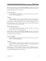
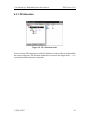
3.5. Database Window
Figure 3-5. Database Window.
In the Database Window side bar, all the database items associated with the design
are listed. Each component from the database is represented as a tab in the Database
Window. Each component contains a number of categories, which contain a number of
database item types. The database item types can be dragged directly from the Database
Window onto the Design Canvas to create an instance of that type for the design. The
Database Window is displayed in Figure 3-5.
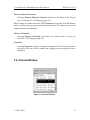
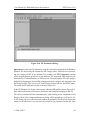
3.6. Output Window
Figure 3-6. Output Window.
The Output Window displays the information related to the process of ESE, such as
logged status, diagnostic and error output of background commands. The Output Window is displayed in Figure 3-6. The Output Window contains six tabs: Compile, Simulate, Verify, Analyze, Synthesize and Shell. The Compile tab displays the log mes-
© 2008, CECS
25
User Manual for Embedded System Environment:
ESE Version 2.0.0
sages generated during preprocessing and parsing of the design file during Synthesis. The Simulate tab displays the log messages generated by the command line tools
spawned by the main application GUI during simulation. The Verify tab displays the
log messages generated by the command line tools spawned by the main application
GUI during verification. The Analyze tab displays the log messages generated by the
command line tools spawned by the main application GUI during analysis. The Synthesize tab displays the log messages generated by the command line tools spawned by
the main application GUI during synthesis. Finally, the Shell tab contains an instance of
the interactive ESE shell interpreter.
The Output Window is mainly for informational purposes and doesn’t contain any button
that users can click. Only the Shell tab allows to enter ESE commands interactively
to be executed by the embedded scripting interpreter. In addition, all tabs support a
context menu through which the user can save the contents of the tab to a file, cut, copy
and paste text between a tab and other applications, toggle line wrapping, and clear
or completely reset the tab. Furthermore, the Shell tab supports history substitution of
previously entered commands via Undo and Redo context menu entries.
The Output Window can be detached or docked. Users can drag the window (by its title
bar or handle) to the desired place. If the Output Window is detached, it can be floating
and displayed anywhere on the desktop. If the Output Window is docked, it has to be
attached to any of the borders of the Main Window.
3.7. Message Boxes
As a result of certain actions, the ESE application will pop up message box dialogs for
feedback to or input from the user about handling of special situations. Message boxes
are used to provide informative messages and to ask simple questions. In general, there
are two types of message boxes: error dialogs and information dialogs.
© 2008, CECS
26
User Manual for Embedded System Environment:
ESE Version 2.0.0
3.7.1. Error Dialogs
Figure 3-7. Error dialog.
If the application encounters an abnormal error situation in which user notification
about the failure of the initiated action is required, an Error dialog will be popped up
(Figure 3-7). The Error dialog displays an error message at the top-half of the Error dialog. At the bottom-half, an Error dialog contains one button: Ok. Clicking Ok will close
the Error dialog and original dialog (if any) that prompted the message. After clicking,
the original action that prompted the message is aborted and cancelled.
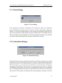
3.7.2. Information Dialogs
Figure 3-8. Information dialog.
If the application encounters an abnormal situation in which user notification is required
and the user is given several choices on how to continue, an Information dialog will be
popped up (Figure 3-8). An information message and associated question is displayed at
the top-half of the dialog. The bottom-half of the dialog contains three buttons: Yes, No,
and Cancel. Clicking Yes will accept the recommendation and do the corresponding
action. Clicking No will not accept the recommendation and will not do the corresponding action but will continue the original action that prompted the message in the first
© 2008, CECS
27
User Manual for Embedded System Environment:
ESE Version 2.0.0
place. Finally, clicking Cancel will not do the recommended action and will also cancel
the original action that prompted the message. Clicking one of above three buttons will
close the Information dialog and original dialog (if any) that prompted the message.
© 2008, CECS
28
User Manual for Embedded System Environment:
ESE Version 2.0.0
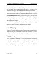
Chapter 4. Functionality
The functionality of ESE can be classified into the following categories: application, file
handling, design-entity handling, and synthesis & simulation,
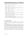
4.1. Application Preferences
The main application of ESE supports a set of persistent application preferences. Application preferences are persistently stored across different invocations of the tool. In fact,
application preferences are shared among all tools in the ESE environment, i.e. they are
persistent across invocation of different tools at different times.
Application preferences are stored in both system-wide and user-specific locations (see
Section 4.2.7 Design Settings Editing (page 39)). System-wide application preferences
affect all users of ESE applications on the system. User-specific application preferences,
on the other hand, are stored in a file in the user’s Linux home directory. The application
first reads the system-wide and then the user-specific settings, i.e. user-specific settings
can override (if given) system-wide settings and if no user-specific settings are given,
application settings default to the system-wide settings. If no system-wide settings are
available, compiled-in defaults are used.
Application preferences in general provide the standard settings (paths, etc.) to use by
default for the different parts of ESE applications.
Application preferences can be edited by the user by selecting
Main::Edit−→Preferences.... This will pop-up the Edit Preferences dialog, which
allow users to browse and specify individual settings. At the bottom of the Edit
Preferences dialog, buttons Ok and Cancel are available. If users click the Ok button,
all the edited preferences are saved. If users click the Cancel button, all the edited
preferences are discarded. Either clicking Ok or Cancel button will close Preference
dialog.
© 2008, CECS
29
User Manual for Embedded System Environment:
ESE Version 2.0.0
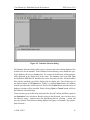
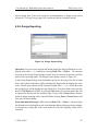
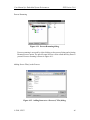
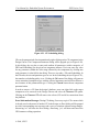
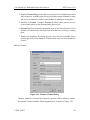
4.1.1. Application Preferences
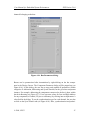
Figure 4-1. Edit Preferences dialog.
Database preferences define the location of the database EDB file for the Database Windows
The Application tab of the Edit Preferences dialog allows for viewing and selecting of
database file path, as well as other include and library paths. The Application tab is
shown in Figure 4-1.
Users can type in the file name and path of the database in the Application’s line edit
boxes. Besides typing in the file name, users can also select the names by using ...
buttons next to the edit box. Clicking ... button will pop up a Database Selection dialog
displayed in Figure Figure 4-2.
© 2008, CECS
30
User Manual for Embedded System Environment:
ESE Version 2.0.0
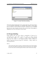
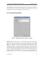
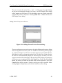
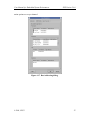
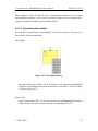
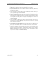
Figure 4-2. Database Selection dialog.
The Database Selection dialog allows users to choose and select existing database files
on disk to use for the database. In the Database Selection dialog, users should first specify the database directory in Look-in box. The content of the directory will be automatically displayed in the display box in the center. The database type in the File Type
box defaults to EDB files for databases but can be chosen by the user. All the database
files with the specified type will be displayed in the display box. Users further type in
the database name in File Name box. Finally, by clicking Open button, the database
with the specified name will be selected. If users click Cancel button, then the action of
database selection will be cancelled. Either clicking Open or Cancel button will close
the Database Selection dialog.
Users can also type in the file name and path of the SystemC include and library paths in
the Application’s line edit boxes. Besides typing in the file name, users can also select
the names by using ... buttons next to the appropriate edit box. Clicking ... button will
pop up a SystemC Path Selection dialog displayed in Figure xref linkend="fig-systemcpath-selection">.
© 2008, CECS
31
User Manual for Embedded System Environment:
ESE Version 2.0.0
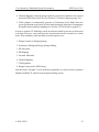
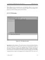
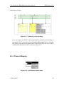
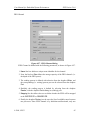
Figure 4-3. SystemC Path Selection dialog.
The SystemC Selection dialog allows users to choose and select a directory on disk to
use for the SystemC include path or the SystemC library path. By clicking Open
button, the directory with the specified name will be selected. If users click Cancel
button, then the action of database selection will be cancelled. Either clicking Open or
Cancel button will close the Database Selection dialog.
4.2. Design Handling
Design handling deals with issues relating to manipulation of design and its
corresponding files within ESE. It allows for tracking of design meta-data
over the whole lifetime of a design. A design contains design-specific
settings that can override or extend application-specific compiler settings (see
Section 4.1 Application Preferences (page 29)). Specifically, a design contains the
following information:
Sources
A list of source files. The list of sources contains the union of all C and/or SystemC
source files from which the models that are part of the design have been compiled.
For each source file, the location (path) of the file on disk is stored in the design.
© 2008, CECS
32
User Manual for Embedded System Environment:
ESE Version 2.0.0
Compiler settings
A set of design-specific options for preprocessing and parsing SystemC source files.
Compiler settings contain include paths, import paths, compiler options, and macro
defines and undefines. Design-specific compiler settings generally overwrite or extend the corresponding application-specific settings. In the case of paths, design
paths are prepended to the standard paths defined in the application settings (i.e.
they are prepended to the directory search list). In all other cases, options or macro
defines/undefined are appended to the compiler command line after the standard
options and macros defined in the application settings.
Designs are stored as ESE Data Structure (EDS, *.eds) files on disk. The design file
format is the same for all tools in the ESE environment, i.e. a design file can be read,
modified and written by any ESE tool.
Design can be read from and saved as design files at any time in the ESE application.
At any time, however, at maximum only one design can be open and loaded. While a
certain design is open and loaded, its settings apply to all actions performed during that
time. In addition, certain actions will automatically update and add data in the currently
opened and loaded design.
Note: All paths in the design settings are defined to be relative to the location of
the design file, i.e. relative paths in a design file are converted into absolute paths
by appending the design file’s directory during loading/opening of a design file.
During saving/writing of design files, absolute paths are in turn converted back to
relative paths if they point to a location below the target design file directory.
In order to deal with management of design files, ESE supports a set of file
handling functions. Design handling includes opening, saving, and closing
of design files on disk. Design handling is closely related to Design Canvas
(Section 3.2 Design Canvas (page 12))
and
Design
Canvas
Management
(Section 4.7 Window Management (page 69)). In general, there is a one-to-one
association between design models, design files on disk and design canvases in the
Workspace. Each Design Canvas represents a view onto one loaded design file
which in turn stores the data of one design model, and vice versa. For example,
both file closing (Section 4.2.5 Design Closing (page 37)) and window closing
(Section 4.7 Window Management (page 69)) will close the design file and the Design
Canvas and unload the design from ESE’s memory.
© 2008, CECS
33
User Manual for Embedded System Environment:
ESE Version 2.0.0
Specifically, file handling consists of the following tasks:
1. Design
Creation
to
create
Section 4.2.1 Design Creation (page 34)).
a
new
design
(see
2. Design Opening to open and load existing design files from disk (see
Section 4.2.2 Design Opening (page 34)).
3. Design
Saving
to
save
the
Section 4.2.3 Design Saving (page 36)).
current
design
4. Design
Closing
to
close
Section 4.2.5 Design Closing (page 37)).
the
current
on
disk
design
(see
(see
5. Design Reloading to reload the current design’s last saved instance (see
Section 4.2.4 Design Reloading (page 37)).
6. Design Exporting to create a compressed archive file of the current design (see
Section 4.2.6 Design Exporting (page 38)).
7. Design Settings to display and edit the settings of the opened design (see
Section 4.2.7 Design Settings Editing (page 39)).
8. ESE Exiting to exit the ESE application (see Section 4.2.9 ESE Exiting (page 41)).
4.2.1. Design Creation
Users can create a new design by selecting Main::File−→New.... This action will clear
all windows (Design Canvas, PE, Channel and Database Windows) in preparation for a
new design.
Error/Information Messages: Assuming before design creation, users have opened another design in ESE, the currently opened design has been modified and the opened
design is not saved yet. When users select Main::File−→New, an Information dialog will be popped up querying whether to save the current design first before creating a new one. If the users accept the recommendation, a Design Saving action (see
Section 4.2.3 Design Saving (page 36)) is performed first. In case of errors creating the
design file (file errors, wrong file format), an error dialog with a corresponding error
message is popped up. Upon confirming the error, the file creating action is cancelled.
© 2008, CECS
34
User Manual for Embedded System Environment:
ESE Version 2.0.0
4.2.2. Design Opening
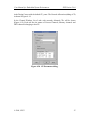
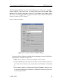
Figure 4-4. Design Open dialog.
Operation: Users can open an existing design file on disk by selecting
Main::File−→Open.... The Design Open dialog window will pop up in which users
can choose and select an existing file on disk to open and load. The Design Open dialog
is illustrated in Figure 4-4.
Users should first specify the directory of the file in Look-in box. The content of the
directory will be automatically displayed in the display box in the center. The file type
defaults to EDS files (*.eds). All the files with the specified type will be displayed in
the display box. Users then further select the file name in the File Name box. Finally,
by clicking the Open button, the file with the specified name will be open. If users click
the Cancel button, the action of file opening will be cancelled. Either clicking Open or
Cancel button will close the File Open dialog.
Opening and loading a design file will result in a corresponding design appearing in the
Design Canvas.
Error/Information Messages: If the specified design file does not exist before clicking
Open button, then clicking Open button has no effect.
In case of errors reading the design file from disk (file errors, wrong file format), an error
dialog with a corresponding error message is popped up. Upon confirming the error, the
Design Opening action is cancelled.
© 2008, CECS
35
User Manual for Embedded System Environment:
ESE Version 2.0.0
Assuming before design opening, users have opened another design in ESE, the opened
design is modified and the opened design is not saved yet. When users open a different
design, the Information dialog will be popped up to recommend users to save the previous design first and, if the recommendation is accepted, a Design Saving action will be
performed. This is the same as the case in task Section 4.2.1 Design Creation (page 34).
4.2.3. Design Saving
Figure 4-5. Design Save dialog.
Operation: Users can save opened and loaded design files (Design Windows in the
Workspace) by one of the following three methods:
1. Selecting Main::File−→Save will save the file of the currently active Design Window using its current name.
2. Users can save the file of the currently active Design Canvas under any (new) name
by selecting Main::File−→Save As.... The selection will pop up the Design Save
dialog in which users can choose the directory and file name to save the design
under. The Design Save dialog is shown in Figure 4-5.
In the File Save dialog, users should first specify the directory of the file in Look-in
box. The content of directory will be automatically displayed in the display box
in the center. The file type defaults to EDS files (*.eds). All the files with the
© 2008, CECS
36
User Manual for Embedded System Environment:
ESE Version 2.0.0
specified type will be displayed in the display box. Users then further select the file
name in File Name box. Finally, by clicking Save button, the current opened file
will be saved as the file with the specified name. If users click Cancel button, then
the action of file saving will be cancelled. Either clicking Save or Cancel button
will close the Design Save dialog.
Error/Information Messages: When selecting Main::File−→Save As... and specifying the file name of an existing design file on disk, an Information dialog will pop up
asking whether to overwrite the existing file. If the users decline this, the design saving
action will be cancelled.
When selecting Main::File−→Save or Main::File−→Save As..., errors may occur (file
errors, e.g. if no space is available on the disk). In this case, an Error dialog as shown in
Figure 3-7 will be popped up, corresponding error messages will be displayed, and the
design saving action will be cancelled.
4.2.4. Design Reloading
Operation: Users can save reload the current design file (Design Windows in the
Workspace) by the following method:
1. Selecting Main::File−→Reload... will save the file of the currently active Design
Window using its current name.
Error/Information Messages: When selecting Main::File−→Reload..., errors may
occur (file errors, e.g. if no space is available on the disk). In this case, an Error dialog as shown in Figure 3-7 will be popped up, corresponding error messages will be
displayed, and the design saving action will be cancelled.
4.2.5. Design Closing
Operation: Users can close the file and window of the currently active Design Window
in the Workspace by selecting Main::File−→Close. Closing a file will unload the design
from memory and will close the corresponding Design Canvas in the Workspace.
Error/Information Messages: If the current design is modified and not yet saved,
selecting Close will pop up an Information dialog which recommends to save the
© 2008, CECS
37
User Manual for Embedded System Environment:
ESE Version 2.0.0
current design first. If the users accept the recommendation, a design saving action
(Section 4.2.3 Design Saving (page 36)) is performed before closing the design.
4.2.6. Design Exporting
Figure 4-6. Design Export dialog.
Operation: Users can export opened and loaded design files (Design Window) as compressed archive file (*.tbz) on disk by selecting Main::File−→Export.... The selection
will pop up the Design Export dialog in which users can choose the directory and file
name to save the design under. The Design Export dialog is shown in Figure 4-6.
In the Design Export dialog, users should first specify the directory of the file in Look
in box. The content of directory will be automatically displayed in the display box in the
center. The file type defaults to ESE Exported Design Files (*.tbz). All the files with
the specified type will be displayed in the display box. Users then further select the file
name in File Name box. Finally, by clicking Save button, the current opened file will
be exported to the file with the specified name. If users click Cancel button, then the
action of design exporting will be cancelled. Either clicking Save or Cancel button will
close the File Export dialog.
Error/Information Messages: When selecting Main::File−→Export... and specifying
the file name of an existing file on disk, an Information dialog will pop up asking whether
to overwrite the existing file. If the users decline this, the file exporting action will be
cancelled.
© 2008, CECS
38
User Manual for Embedded System Environment:
ESE Version 2.0.0
When writing files to disk, errors may occur (file errors, e.g. if no space is available on
the disk). In this case, an Error dialog will be popped up, corresponding error messages
will be displayed, and the file exporting action will be cancelled.
4.2.7. Design Settings Editing
Figure 4-7. Design Settings (TLM Compiler tab) dialog.
Operation: Design setting allows users to edit design settings. Unlike application
preferences editing in Section 4.1 Application Preferences (page 29), design setting
apply only to the current design. Users start design settings editing by selecting
Main::File−→Settings.... The selection will pop up the Design Settings dialog, which
is displayed in Figure 4-7. In the Design Settings dialog, users can access and edit the
TLM Compiler and TLM Simulator tags with corresponding settings stored in the
design. The TLM Compiler tab contains line edit boxes for all compiler settings. The
Compile Options and Link Options lines allow users to customize compilation and
linking of design source files. The text in the Include Path and Import Path lines
© 2008, CECS
39
User Manual for Embedded System Environment:
ESE Version 2.0.0
defines the directory lists (separated by colons “:”) for the project-specific include
and import paths, respectively. The text in the Defines and Undefines lines define
the list of macro defines and undefines (separated by semicolons “;”), respectively.
The text in the Options line defines the project’s compiler options/switches. Finally,
Verbosity Level and Warning Level define verbosity level and warning level so that
all tasks performed are logged and warning messages are enabled, respectively.
See Section 4.1 Application Preferences (page 29) for more details about compiler
settings. Similarly, the TLM Simulator tab includes the following options for output
display of simulation (Output): No terminal, Terminal window, or outputting in the
External console defined by users. Further, users can enable simulation logging by
checking the appropriate check-box. Finally, line edit boxes Simulation Options and
Post-simulation command define directives to the simulation engine during and after
TLM simulation.
4.2.8. Design Source Viewing
Figure 4-8. Design Source Viewing dialog.
Operation: The source file of the design can be viewed via View−→Source.... The
© 2008, CECS
40
User Manual for Embedded System Environment:
ESE Version 2.0.0
result of View−→Source... is shown in Figure 4-8.
4.2.9. ESE Exiting
Operation: Selecting Main::File−→Exit will exit the ESE application and close the
ESE GUI.
Error/Information Messages: If there is an open Design Canvas that is modified and
not yet saved, an Information dialog will pop up querying whether to save the corresponding design. The users will be able to cancel the whole exit action via the corresponding dialog button. If the users accept the recommendation to save the file, a file
saving action will be triggered (see Section 4.2.3 Design Saving (page 36)). Note that
the design saving action can trigger additional Error dialogs which in turn can abort the
whole exit operation in case of file errors during saving.
4.3. Transaction Level Modeling
Transaction Level Modeling is a process of implementing a system specification on a
platform consisting of PEs and memories interconnected with busses and CEs (bridges,
transducers), in order to generate a respective transaction level model (TLM) of the design. During TL Modeling, the designers allocate PEs and memories, busses and CEs
and connect them into an intergral system platform. During mapping, the designers map
computation processes to the PEs and end-to-end communication channels to the network of PEs, CEs and busses. Processes are units of computation in the specification.
The end-to-end channels connect processes to enable interprocess data exchange, or connect a process with the memory for data storing. Specifically, Transaction Level Modeling consists of the following tasks:
1. PE Allocation to allocate and select PEs/memories from the PE
database in order to assemble the system’s computing architecture (see
Section 4.3.1 PE Allocation (page 42)).
2. PE Mapping to map the design’s computation entities (or processes) to the selected
PEs (see Section 4.3.2 PE Mapping (page 45)).
3. Network Allocation to allocate, select and define the communication network topology (see Section 4.3.3 Network Allocation (page 49)).
© 2008, CECS
41
User Manual for Embedded System Environment:
ESE Version 2.0.0
4. Channel Mapping to map the design’s global, system-level channels to the selected
network of PEs, busses and CEs (see Section 4.3.4 Channel Mapping (page 58)).
5. TLM synthesis to automatically generate an Transaction Level Model from the
given specification based on the decision made during the allocation of components
and application-to-platform mapping (see Section 4.4 TLM Synthesis (page 63)).
In order to perform TL Modeling, not all the tasks described in previous sections need
to be done. However, some tasks must be executed and must be executed in a certain
order. These mandatory tasks and their execution sequence are:
1. Design Creation or Design Opening.
2. Preferences Editing and Design Settings Editing.
3. PE Allocation.
4. PE Mapping.
5. Network Allocation.
6. Channel Mapping.
7. TLM Synthesis.
8. Design Saving and/or ESE Exiting.
Note that steps 3 through 7 can be performed repeatedly in a loop in order to generate
multiple candidate TL models in one design modeling session.
© 2008, CECS
42
User Manual for Embedded System Environment:
ESE Version 2.0.0
4.3.1. PE Allocation
Figure 4-9. PE Allocation result.
Users can select PEs/memories out of the PE database in order to allocate and assemble
the system architecture. PE allocation information is stored in the design itself ( *.eds)
as an annotated Data Structure component.
© 2008, CECS
43
User Manual for Embedded System Environment:
ESE Version 2.0.0
Figure 4-10. PE Parameters dialog.
Operation: In order to do PE allocation, users first select Processing tab in the Database
Window. The Processing tab contains the PE category table, with each row representing one category of PEs in the database. For example, row SW Processors contains
all the general-purpose processors in the database. The supported EDS categories are
Hardware IPs, Custom Hardware or SW Processor. The users add the PE to the design’s
platform by dragging the desired EDS component from its category and dropping it into
the Design Canvas. This creates a PE in the Design Canvas with the default PE_name.
The result of a PE Allocation action is shown in Figure 4-9.
In the PE Window, list of tabs with currently allocated PEs will be shown (Figure 4-9).
Each tab lists the names of Processes, Memories and Channels belonging to that PE.
PEs can be parametrized after instantiation by right-clicking on the component in the
Design Canvas. The Component Parameter dialog will be popped up (see Figure 4-10).
In this dialog, the users can enter and confirm all parameters for the given component
instance to be allocated. Users can enter any value for any parameter (within the value
© 2008, CECS
44
User Manual for Embedded System Environment:
ESE Version 2.0.0
range allowed by the component) by clicking into each parameter’s value field in the
dialog. Clicking the Ok button of the dialog will generate a new customized component type with the selected parameters and will then allocate a new instance of this
parametrized type. Clicking the Cancel button aborts component parametrization.
In order to remove a PE from the design’s platform, users can right-click on the target
PE to be removed in the Design Canvas and select the Remove PE option. Clicking on
the Remove PE will remove the selected PE from the list of allocated PEs.
Error/Information Messages: During PE editing, if users try to give PEs a name which
is already used as the name of another PE in the design, an Error dialog will be popped
up with a corresponding error message and a query to continue without saving changes.
Answering ’no’ will close the Error dialog. Answering ’yes’ will abort and cancel the
PE Parameters editing operation.
During PE adding, when adding a PE, the selected PE type is read from the database.
In case of errors during database opening (e.g. file errors or wrong file format), an Error
dialog will be popped up and the PE adding operation will be aborted.
4.3.2. PE Mapping
In order to implement the computation in the design model on the allocated computation
architecture consisting of PEs and memories, users have to be able to map the processes,
variables (memory) and channels in the specification onto the allocated PEs. Hence,
mapping consists of separate process mapping, memory mapping, and channel mapping
tasks.
4.3.2.1. Process Mapping
Process mapping allows for mapping of process types/classes in the design onto allocated PEs, i.e. process mapping information is stored as annotations at the process
classes in the design. A process is mapped to the PE by right-clicking on the corresponding PE tab in the PE Window and selecting Add Process option. This creates a
process listing in the PE tab with the default process name. Process mapping information consists of proces name, source files and process ports and it can be accessed for
editing with right-clicking on the process listing.
© 2008, CECS
45
User Manual for Embedded System Environment:
ESE Version 2.0.0
Process Renaming
Figure 4-11. Process Renaming dialog.
Process renaming is accessed by right-clicking on the process listing and selecting
Rename Process option. The process name line box can be edited until key Enter is
pressed. Process renaming is shown in Figure 4-11.
Adding Source File(s) to the Process
Figure 4-12. Adding Sources to a Process (C File) dialog.
© 2008, CECS
46
User Manual for Embedded System Environment:
ESE Version 2.0.0
The users can add source files (*.c and *.h) to the process by right-clicking on the
process listing and selecting Add .C File(s) and Add .H File(s) options, respectively.
An Open dialog will be popped up (see Figure 4-12). In this dialog, users should
first specify the file(s) directory in Look-in box. The content of the directory will be
automatically displayed in the display box in the center. The file(s) type in the File
Type box defaults to C source files (*.c) or C header files (*.h), depending on the
selected option. All the source/header files with the specified type will be displayed
in the display box. Users further type in the file name(s) in File Type box. Finally,
by clicking Open button, the file(s) with the specified name(s) will be selected. If
users click Cancel button, then the action of database selection will be cancelled.
Either clicking Open or Cancel button will close the Open dialog.
Viewing Source File(s) of the Process
Figure 4-13. Adding Sources to a Process (C File) dialog.
© 2008, CECS
47
User Manual for Embedded System Environment:
ESE Version 2.0.0
The users can view the source file(*.c and *.h) of the process by right-clicking
on the process listing and selecting View Source. An ESE Design Viewer dialog
will be popped up (see Figure 4-13). In this dialog, users can view the source file
textually and search for keywords. Choosing Main::File−→Close will close the
ESE Design Viewer dialog.
Adding Process Port(s) to the Process
Figure 4-14. Adding a Process Port to a Process dialog.
The users add process ports to the process by right-clicking on the process listing
and selecting Add Process Port option. An Add Process Port dialog will be popped
up, as shown in Figure 4-14. The users can name the process port in Name line box,
and define its type by selecting one option in the Type drop box. Upon selection,
the API box will automatically display the selected type(s) of API(s). The users
can then name the API(s) belonging to that port by double-clicking and writing the
API functions in the appropriate lines of the display box. Finally, by clicking Add
button, the process port with the specified API(s) will be selected. If users click
Cancel button, then the action of creating a process port will be cancelled. Either
clicking Open or Cancel button will close the Add Process Port dialog.
© 2008, CECS
48
User Manual for Embedded System Environment:
ESE Version 2.0.0
4.3.2.2. Local Memory Mapping
Memory mapping allows for mapping of variable instances in the design into exposed
memories of allocated regular PEs. An exposed memory is added to the PE by rightclicking on the corresponding PE tab in the PE Window and selecting Add Exposed
Memory option. This creates a memory listing in the PE tab with the default memory
name. Memory mapping information consists of memory name and size and it can be
accessed for editing with right-clicking on the memory listing.
4.3.2.3. Local Channel Mapping
Channel mapping attributes an end-to-end channel to a pair of processes. Depending
on the selected route, a channel can be either local (i.e. belonging to a single
PE), or global (i.e. connecting processes of different PEs), mapped to the network
of busses and CEs. Local and global channel mapping is uniformly described in
Section 4.3.4 Channel Mapping (page 58).
4.3.3. Network Allocation
Network allocation and connection information is stored in the design itself ( *.eds) as
an annotated Data Structure allocation and connection tables.
Network topology includes an interconnection of communication busses and communication elements (CEs). The end-to-end channels that implement communication between processes are then mapped to the routes of busses and CEs connecting those
processes. Hence, network allocation consists of separate bus allocation, CE allocation,
network connecting and channel mapping tasks.
© 2008, CECS
49
User Manual for Embedded System Environment:
ESE Version 2.0.0
4.3.3.1. Bus Allocation
Figure 4-15. Bus Allocation result.
Operation: In order to allocate a bus, users first select Communication tab in the
Database Window. The Communication tab contains the communication category
table, with each row representing one category of communication media in the
database. For example, category Bus includes all busses supported with the database.
The EDS communication categories are Network, Bus and Link. The user adds the
communication component to the design’s platform by dragging the desired EDS
component from its category and dropping it into the Design Canvas. This creates a bus
in the Design Canvas with the default Bus_name. The result of a Network Allocation
(adding a bus) action is shown in Figure 4-15.
In the Channel Window, list of tabs with currently allocated busses will be shown
(Figure 4-15). Each tab lists the names of Process Channels, Memory channels and FIFO
© 2008, CECS
50
User Manual for Embedded System Environment:
ESE Version 2.0.0
channels belonging to that bus.
Figure 4-16. Bus Parameters dialog.
Busses can be parametrized after instantiation by right-clicking on the bus component in the Design Canvas. The Component Parameter dialog will be popped up (see
Figure 4-16). In this dialog, the user has to enter and confirm all parameters (within
categories of Arbitration, Addressing and Synch/Transfer) for the given bus component
instance. For example, addressing the components connected to the bus is done within
the tab Addressing (see Figure 4-17). Users can enter values for Low and High Address
for any component (a Channel, CE port or a Memory) by clicking into each parameter’s
value field in the dialog. To set the synchronization type for each channel, the user has
to click on the Sync/Transfer tab (see Figure 4-18). Here, synchronization and packeti-
© 2008, CECS
51
User Manual for Embedded System Environment:
ESE Version 2.0.0
zation options are set per channel.
Figure 4-17. Bus Addressing dialog.
© 2008, CECS
52
User Manual for Embedded System Environment:
ESE Version 2.0.0
Figure 4-18. Bus Synchronization dialog.
Clicking the Ok button of the dialog will generate a new customized component type
with the selected parameters and will then allocate a new instance of this parametrized
type. Clicking the Cancel button aborts component parametrization.
In order to remove a bus from the design’s platform, users can right-click on the target
bus to be removed in the Design Canvas and select the Remove Bus option. Clicking on
the Remove Bus will remove the selected Bus and all its connections from the platform.
Error/Information Messages: During bus editing, if users try to give busses a name
which is already used as the name of another bus in the design, an Error dialog will be
popped up with a corresponding error message and a query to continue without saving
changes. Answering ’no’ will close the Error dialog. Answering ’yes’ will abort and
cancel the Bus Parameters editing operation.
© 2008, CECS
53
User Manual for Embedded System Environment:
ESE Version 2.0.0
When adding a bus, the selected bus type is read from the database. In case of errors
during database opening (e.g. file errors or wrong file format), an Error dialog will be
popped up and the PE adding operation will be aborted.
4.3.3.2. CE Allocation
Figure 4-19. CE Allocation result.
Operation: In order to allocate a CE, users first select CE tab in the Database Window.
The CE tab contains the CE category table, with each row representing one category of
CEs in the database. For example, category Bridge includes all bridges supported with
the database. The EDS communication categories are Router, Transducer and Bridge.
The user adds the CE component to the design’s platform by dragging the desired EDS
component from its category and dropping it into the Design Canvas. This creates a CE
© 2008, CECS
54
User Manual for Embedded System Environment:
ESE Version 2.0.0
in the Design Canvas with the default CE_name. The Network Allocation (adding a CE)
is shown in Figure 4-19.
In the Channel Window, list of tabs with currently allocated CEs will be shown
(Figure 4-19). Each tab lists the names of Process Channels, Memory channels and
FIFO channels belonging to that CE.
Figure 4-20. CE Parameters dialog.
© 2008, CECS
55
User Manual for Embedded System Environment:
ESE Version 2.0.0
Figure 4-21. CE Scheduling dialog.
CEs can be parametrized after instantiation by right-clicking on the CE component in the
Design Canvas. The Component Parameter dialog will be popped up (see Figure 4-20).
In this dialog, the user has to enter and confirm all parameters (within categories of
FIFO and Scheduling) for the given bus component instance. Users can enter any value
for any parameter (within the value range allowed by the component) by clicking into
each parameter’s value field in the dialog. There are two tabs = Fifo and Scheduling. In
the Fifo tabe, the size and partition types are set. In the Scheduling tab (see Figure 4-21),
the transducer scheduling policy is set. Clicking the Ok button of the dialog will generate
a new customized component type with the selected parameters and will then allocate a
new instance of this parametrized type. Clicking the Cancel button aborts component
parametrization.
In order to remove a CE from the design’s platform, users can right-click on the target
component to be removed in the Design Canvas and select the Remove CE option.
Clicking on the Remove CE will remove the selected CE and all its connections from
the platform.
Error/Information Messages: During CE editing, if users try to give CEs a name which
is already used as the name of another CE in the design, an Error dialog will be popped
up with a corresponding error message and a query to continue without saving changes.
Answering ’no’ will close the Error dialog. Answering ’yes’ will abort and cancel the
CE Parameters editing operation.
© 2008, CECS
56
User Manual for Embedded System Environment:
ESE Version 2.0.0
When adding a CE, the selected CE type is read from the database. In case of errors
during database opening (e.g. file errors or wrong file format), an Error dialog will be
popped up and the PE adding operation will be aborted.
4.3.3.3. Connecting the network
The network is constructed by connecting PEs and CEs to the busses. This process is
done with the following operations:
Port Adding
Figure 4-22. Port Adding dialog.
By right-clicking onto a PE or CE in the Design Canvas and selecting Add Port
option, the user attributed the communication port to that PE/CE. The Port Adding
is shown in Figure 4-22.
Remove Port
Right-clicking onto a PE’s or CE’s port and selecting the Remove Port from the
context menu will remove that port from the corresponding PE or CE.
© 2008, CECS
57
User Manual for Embedded System Environment:
ESE Version 2.0.0
Connecting to the Bus
Figure 4-23. Connecting to the bus dialog.
Users can connect the PE/CE to the bus (named Bus_name) by right-clicking on
the created PE/CE’s port and selecting Connect toBus_name option. Generally,
PE/CE ports can connected to busses either as bus master (M), bus slave (S) or as
combined bus master/slave (MS). as shown in Figure 4-23.
4.3.4. Channel Mapping
Figure 4-24. Add Channel context menu.
© 2008, CECS
58
User Manual for Embedded System Environment:
ESE Version 2.0.0
Channel mapping attributes an end-to-end channel to a pair of processes. Creating a
channel begins by right-clicking onto a Channel Window and selecting Add Channel option. This action is shown on in Figure 4-24. The Channel Type dropbox allows
the users to select among the following types of channels: Process-to-Process Channel,
Memory Channel and FIFO Channel.
Process-to-Process Channel
Figure 4-25. Process-to-Process Channel dialog.
Process-to-Process Channel is defined with the inputting the values of the following parameters, as shown in Figure 4-25:
1. Name line box defines a unique name identifier for the channel.
2. Dropbox Direction provides options of Unidirectional and Bidirectional channel. Unidirectional channels only transfer data from Process 1 to Process
2.
3. If the channel is defines as Unidirectional, dropbox Process 1 allows the users
to select the sending process. Otherwise, it defines the first process in the communicating process pair.
© 2008, CECS
59
User Manual for Embedded System Environment:
ESE Version 2.0.0
4. Dropbox Process Port provides the users with the list of available ports of the
selected process. Available ports have no previously assigned channels to them
and are, if the channel is Unidirectional, defined as sending or writing ports.
5. Similarly to Process 1, dropbox Process 2 defines either process receiver,
or the second process in the communicating process pair.
6. Process Port lists previously unassigned ports of the selected process. If the
channel is Unidirectional, the listed ports are defined as receiving or reading
ports.
7. Finally, two dropboxes for routing give the users the list of available routes
between processes. If the channel is Unidirectional, only one of the dropboxes
is active.
Memory Channel
Figure 4-26. Memory Channel dialog.
Memory Channel is a channel that connects a process with the Memory element.
The channel is defined with the following parameters, as shown in Figure 4-26:
© 2008, CECS
60
User Manual for Embedded System Environment:
ESE Version 2.0.0
1. Name line box defines a unique name identifier for the channel.
2. Dropbox Direction allows users to define a channel as: Read only, Write only
or Read/write channel.
3. Users can select the process that accesses the Memory from the list of processes presented in the dropbox Process.
4. Dropbox Process Port provides the users with the list of available ports of the
selected process. Available ports have no previously assigned channels to them
and are defined as reading and/or writing ports (depending on the selection in
channel Direction).
5. Users can define the Memory that Process reads from and/or writes into by
selecting from the dropbox Memory. Only memories accessable (i.e. exposed)
to the channel are listed here.
6. Low Address and High Address line boxes allow the user to define the address range of the Memory that is accessable to the Process via this channel.
7. Finally, two dropboxes for routing give the users the list of available routes
between a Process and a Memory. If the channel is Read only, the dropbox
Memory->Process is the only one active for selection. If the channel is Write
only, the active dropbox is Process->Memory.
© 2008, CECS
61
User Manual for Embedded System Environment:
ESE Version 2.0.0
FIFO Channel
Figure 4-27. FIFO Channel dialog.
FIFO Channel is defined with the following parameters, as shown in Figure 4-27.
1. Name line box defines a unique name identifier for the channel.
2. Next, the line box Size defines the storage capacity of the FIFO channel. (i.e.
the depth of the FIFO queue).
3. The sending process is defined with selection from the dropbox Writer, and
the corresponding (i.e. writing) process port can be selected from the dropbox
Port.
4. Similarly, the reading process is defined by selecting from the dropbox
Reader, with the dropbox Port defining its (reading) port.
5. Mapping line box allows the user to define whether the FIFO will be mapped
to the WRITER PE or READER PE.
6. Finally, the dropbox Route gives the users the list of available routes between
two processes. Since FIFO channel is by definition unidirectional, only one
© 2008, CECS
62
User Manual for Embedded System Environment:
ESE Version 2.0.0
dropbox defines the route.
Reviewing Channel Properties
After creating a channel, users can access channel properties by right-clicking on
the listing of the channel whose properties they wish to review and selecting Properties option. Channel listings Process Channels, Memory Channels and FIFO Channels for are located in the Channel Window.
Removing a Channel
Users can remove created channels by right-clicking on the channel listing in the
Channel Window and selecting Remove Channel option. This action releases all
the ports that were assigned to the removed channel.
In order to add a defined channel to the design, users can edit the listed channel parameters and click the Add button. If users click Cancel button, then all unsaved user
selections will be cancelled. Either clicking the Add or Cancel button will close the
Add Channel dialog.
Every channel connected to a system bus must be assigned an address range. Base addresses and address masks define the address space occupied by the channel on the bus,
i.e. they define the address decoding to be performed for that channel. Note that address
ranges will later be used for automatic address selection during bus parameter assignment. The addresses of channels mapped to the same bus must not overlap.
Error/Information Messages: There are several errors that can happen during bus or
CE allocation:
1. When adding a bus or CE to the allocation via the Bus or CE Selection dialog, the
selected bus/CE type is read from the database. In case of database read errors (file
errors, database format errors) during this operation, an Error dialog will be popped
up and the Bus/CE Adding operation aborted.
2. In addition, if during port name editing users try to give ports a name which is
already used as the name of another port of the same PE/CE, a corresponding Error
dialog will be shown and the renaming operation is cancelled.
© 2008, CECS
63
User Manual for Embedded System Environment:
ESE Version 2.0.0
4.4. TLM Synthesis
4.4.1. Generate Functional TLM
Generation of the functional TLM includes generating SystemC code for the created
design, compiling and linking the design files into an executable tlm binary. The code
generation is started by selecting Main::Synthesis−→Generate Timed TLM option
in the main menu.
4.4.2. Generate TLM
Generation of the timed TLM includes generating SystemC code annotated with the estimated values of execution time for computation and communication, compiling and
linking the design files into an executable tlm. The code generation is initiated by selecting Main::Synthesis−→Generate Timed TLM.
4.5. TLM Validation
4.5.1. Simulate Functional TLM
Simulation of the functional TLM is started by selecting Main::Validation−→Simulate
Functional TLM. This will pop-up the Simulation Output Window dialog, which allow
users to validate the correctness of the functional TLM execution.
4.5.2. Simulate Timed TLM
Simulation of the timed TLM is started by selecting Main::Validation−→Simulate
Timed TLM. This will pop-up the Simulation Output Window dialog, which allow users
to validate the correctness of the timed TLM execution.
4.6. Performance Analysis
Following a successful timed TLM simulation, users can access and analyze the esti-
© 2008, CECS
64
User Manual for Embedded System Environment:
ESE Version 2.0.0
mated performance of the created design at the transaction level of communication. The
total cycles for the system simulation is shown in the output terminal, and it is also recorden in the file {project_name}.cyc. The performance of PEs, CEs and bus components
in the design model can be reviewed by right-clicking on the component of interest in
the Design Canvas and selecting the View Graph... option.
4.6.1. PE Performance Analysis
Figure 4-28. PE Performance Analysis dialog.
© 2008, CECS
65
User Manual for Embedded System Environment:
ESE Version 2.0.0
Figure 4-29. PE Computation graph dialog.
Figure 4-30. Process Computation graph dialog.
PE Performance Analysis graph is accessed with right-clicking on that PE in the Design Canvas and selecting View Graph... option. This action pops-up a pie chart of the
selected PE’s performance, divided into the categories of idle time, Real-Time Operating System (RTOS) overhead time, time spent on communication and time spent on
computation (idle, RTOS, comm, comp, respectively). The PE performance pie chart is
shown in Figure 4-28. By clicking on the computation slice, another pie chart is shown
(see Figure 4-29). It displays the processes slice in the PE computation time. By further
© 2008, CECS
66
User Manual for Embedded System Environment:
ESE Version 2.0.0
clicking on a process, the user can see the different functions which compose the process (see Figure 4-30). The pie chart can be customized by accessing Main::Customize
menu. The available options in viewing the performance graph are as follows:
No Explode / Medium Explode / Heavy Explode
No Explode is a default option for viewing a pie chart, which differentiates the
seperate slices of the pie by color alone. Users can emphasize the separation between pie slices by selecting Medium or Heavy Explode, which, in addition to use
of color, injects extra space between pie slices.
Quantifying PE Performance
PE’s performance in terms of idle time and times spent on communication and
computation can be quantified with a ratio, their absolute values (in clock cycles),
percentage values or with their respective idle/comm/comp labels.
Closing Performance Analysis Window
The pie chart window is closed by selecting Main::Window−→Close menu.
4.6.2. Bus Performance Analysis
Figure 4-31. Bus Performance Analysis dialog.
© 2008, CECS
67
User Manual for Embedded System Environment:
ESE Version 2.0.0
Figure 4-32. Bus Data Transfer Analysis dialog.
Bus Performance Analysis graph is accessed with right-clicking on the desired bus in
the Design Canvas and selecting View Graph... option. This action pops-up a pie chart
of the selected bus’ performance, divided into the categories of idle time, time spent on
fetching instruction/data (if the Program/Data is stored in the external memory) and time
spent on transferring messages between processes (idle, Program/Data, data transfer,
respectively). The bus performance pie chart is shown in Figure 4-31. By clicking on
the Data Transfer slice, the breakdown of the data transfer by channels is shown (see
Figure 4-32). The pie chart can be customized by accessing Main::Customize menu.
The available options in viewing the performance graph are as follows:
No Explode / Medium Explode / Heavy Explode
No Explode is a default option for viewing a pie chart, which differentiates the
seperate slices of the pie by color alone. Users can emphasize the separation between pie slices by selecting Medium or Heavy Explode, which, in addition to use
of color, injects extra space between pie slices.
Quantifying Bus Performance
The bus performance in terms of idle time and times spent on fetching program in-
© 2008, CECS
68
User Manual for Embedded System Environment:
ESE Version 2.0.0
structions/data and data transfer can be quantified with a ratio, their absolute values
(in clock cycles), percentage values or with their respective labels.
Closing Performance Analysis Window
The pie chart window is closed by selecting Main::Window−→Close menu.
4.6.3. CE Performance Analysis
CE Performance Analysis graph is accessed with right-clicking on the desired CE in
the Design Canvas and selecting View Graph... option. This action pops-up a pie chart
of the selected CE’s performance, divided into the categories of time spent checking
for process requests and time spent on storing and forwarding messages to and from
the internal FIFO (fifo_check and fifo_read_write, respectively). The pie chart can be
customized by accessing Main::Customize menu. The available options in viewing the
performance graph are as follows:
No Explode / Medium Explode / Heavy Explode
No Explode is a default option for viewing a pie chart, which differentiates the
seperate slices of the pie by color alone. Users can emphasize the separation between pie slices by selecting Medium or Heavy Explode, which, in addition to use
of color, injects extra space between pie slices.
Quantifying CE Performance
The bus performance in terms of times spent on checking the internal FIFO and
reading from and writing into the FIFO can be quantified with a ratio, their absolute
values (in clock cycles), percentage values or with their respective labels.
Closing Performance Analysis Window
The pie chart window is closed by selecting Main::Window−→Close menu.
© 2008, CECS
69
User Manual for Embedded System Environment:
ESE Version 2.0.0
4.7. Window Management
Window management deals with the management of Design Windows in the Workspace.
Window management allows for closing, resizing, and arranging of multiple simultaneously opened Design Windows within the Workspace. Specifically, the tasks for window
management are:
Window Closing
Users can close the currently active Design Canvas in the Workspace by selecting
Main::Window−→Close. In addition, any of the Design Windows can be closed
by clicking on a respective icon in the window’s title bar.
Users can close all the currently opened Design Canvass in the Workspace by selecting Main::Window−→Close All.
In all cases, closing a Design Canvas triggers a file closing action for the corresponding design file (see Section 4.2.5 Design Closing (page 37)).
Window Arranging
Users can automatically arrange Design Canvass in the Workspace in a variety
of manners. Selecting Main::Window−→Tile will rearrange the Design Canvass
in the Workspace in a tiled fashion. Selecting Main::Window−→Cascade will
rearrange the Design Canvass in the Workspace in a cascaded manner. Apart from
that, windows can be freely resized and moved within the Workspace by dragging
their title bar or borders. In addition, users can maximize and minimize Design
Windows by clicking on a respective icon on the window’s title bar.
Window Switching
Selecting Main::Window−→Next or Main::Window−→Previous will switch the
focus to and activate the next/previous Design Window in the list of opened windows. Using these actions, users can cycle through the list of windows. Design
Windows are ordered in the window list according to the order in which they were
opened. In addition, users can activate and raise any of the opened Design Windows
by clicking into the window.
Finally, the bottom of the Main::Window menu contains entries for all currently
opened Design Windows. Selecting any of these menu entries will activate and
raise the corresponding Design Canvas.
© 2008, CECS
70
User Manual for Embedded System Environment:
ESE Version 2.0.0
Window Toggling
Selecting Main::Window−→Project Manager or Main::Window−→Output
Window will toggle (turn on and off) displaying of the Project Window and
Output Window, respectively.
© 2008, CECS
71
User Manual for Embedded System Environment:
ESE Version 2.0.0
Chapter 5. Data Modeling
5.1. Processing Element (PE) Data Model
PE Data Model characterizes the structure of PE and a memory sub-system. It consists
of the following three data models: Datapath Model, Execution Model, and Memory
Model.
Table 5-1. Model
Name
ProcUnit
Sub-Models
DPModel, ExecModel, MemModel
Table 5-2. Attribute
Name
Description
Name for type
of processing
element
type
Value
User defined
Identifier
Type
String
Source
User define
5.1.1. Datapath Model
Datapath model has a set of functional units and pipelines. It enumerates all the pipelines
and functional units available in the PE. Multiple pipelines are allowed for superscalar
architectures. This model is composed of a set of pipeline models and a set of functional
unit models.
Table 5-3. Model
Name
DPModel
Sub-Models
FuncUnit, Pipeline
5.1.1.1. Functional Unit Model
This model consists of type of a functional unit and its quantity in the PE. Delay for the
functional unit is specified in operation model explained later.
© 2008, CECS
72
User Manual for Embedded System Environment:
ESE Version 2.0.0
Table 5-4. Model
Name
FuncUnit
Sub-Models
OperMode
Table 5-5. Attribute
Name
type
quantity
Description
Value
Name for type
User defined
of functional
Identifier
unit
Number of the
functional units
≥1
available in the
PE
Type
Source
String
User define
Int
Data sheet
5.1.1.1.1. Operation Model
Functional unit can operate in several modes. For each modes, it has different delays.
For example, ALU may have addition and multiplication modes with different delays.
In this model, delays for each operation modes are specified.
Table 5-6. Model
Name
OperMode
Sub-Models
Table 5-7. Attribute
Name
mode
oplat
© 2008, CECS
Description
Value
Name for type User defined
of mode
Identifier
Delay of
functional unit
≥1
for the
operation mode
Type
Source
String
User define
Int
Data sheet
73
User Manual for Embedded System Environment:
ESE Version 2.0.0
5.1.1.2. Pipeline Model
Pipeline model consists of a name and a set of pipeline stages. It also defines branch
delay model which is a statistical model that stores the branch prediction policy, cycles
lost for mis-prediction and the average mis-prediction ratio. Please note that current
version of ESE does not use branch prediction policy for now. This attribute will be
used when ESE supports a dynamic branch prediction model.
Table 5-8. Model
Name
Pipeline
Sub-Models
Stage
Table 5-9. Attribute
Name
Description
Identifier for
name
the pipeline
Branch
br_pred_policy prediction
policy
Cycle lost for
br_penalty
mis-prediction
br_pred_hit_ratio
Hit ratio from
branch
prediction
Value
User defined
Identifier
Type
Source
String
User define
TAKEN,
NOT_TAKEN
String
User select
Number of
cycles
Int
≥0.00,
≤100.00
FP
Data sheet on
PE
Simulation
result by ISS or
virtual platform
5.1.1.2.1. Pipeline Stage Model
Pipeline stage model has a set of pointers to a functional unit that is available in that
pipeline stage. It consists of a set of pointers to functional unit model. Please note that we
can describe non-pipelined datapath by defining only 1 stage inside of pipeline model.
For this, please refer to the example of custom hardware in an Appendix B.
Table 5-10. Model
Name
© 2008, CECS
Sub-Models
74
User Manual for Embedded System Environment:
Name
Stage
ESE Version 2.0.0
Sub-Models
FURef
Table 5-11. Attribute
Name
name
Description
Identifier for
the pipeline
stage
Value
User defined
Identifier
Type
String
Source
User define
5.1.1.2.1.1. Pointer to Functional Unit Model.
Pointer to functional unit model consists of type of functional unit and number of available functional units in the pipeline stage.
Table 5-12. Model
Name
FURef
Sub-Models
Table 5-13. Attribute
Name
type
quantity
© 2008, CECS
Description
Name for type
of a functional
unit
Value
Type of a
functional unit
≥1, ≤ the
Number of
quantity of
functional units
functional unit
available in the
in Datapath
pipeline stage
model
Type
String
Int
Source
Datapath model
Datapath model
75
User Manual for Embedded System Environment:
ESE Version 2.0.0
5.1.2. Execution Model
Execution model consists of a set of operation models and scheduling policy. Each operation model maps a operation to Datapath model and the scheduling policy decides the
execution order for a given stream of operations.
Table 5-14. Model
Name
ExecModel
Sub-Models
Operation
Table 5-15. Attribute
Name
sched
Description
Operation
scheduling
algorithm used
by the PE such
as ASAP,
ALAP, List
scheduling etc.
Value
PIPELINE,
LIST_SCHED
Type
String
Source
User select
5.1.2.1. Operation Model
This model consists of the LLVM operations and their mapping to a pipelined datapath
as defined in Datapath model. Please note that operation model uses LLVM operations
instead of the specific set instruction sets or operations to make estimation framework
re-targettable. LLVM operations can be easily mapped to the operations or instructions
supported by the PE. To give an example, ’add’, ’addc’, ’addk’ and ’addkc’ instructions
in the instruction set of MicroBlaze can be mapped to ’add’ operation in LLVM instruction set. One LLVM operation can take care of several data types. Therefore, data type
of variable for the operation should be also specified. Unless data type for the operation
is not specified, no input or integer type is assumed.
The mapping of LLVM operation to a pipelined datapath consists of two steps. The first
step is to map an operation to a set of pipeline stages and the second is to map available
functional units to the pipeline stage. This mapping is done by two references, pipeline
stage reference and functional unit reference explained later.
© 2008, CECS
76
User Manual for Embedded System Environment:
ESE Version 2.0.0
Table 5-16. Model
Name
Operation
Sub-Models
StgRef
Table 5-17. Attribute
Name
name
var_type
Description
Name of LLVM
instruction
Type of operand
for LLVM
instruction
Value
LLVM
instruction
int, float,
double
Type
String
String
Source
A set of LLVM
instruction
User select
5.1.2.1.1. Pipeline Stage Reference
The pipeline stage reference consists of two flags and a pointer to a pipeline stage defined
in Datapath model. Two flags are ’demand operand’ and ’commit result’ that specify the
pipeline stages where the operation needs operand and commits the result, respectively.
Table 5-18. Model
Name
StgRef
Sub-Models
FURef
Table 5-19. Attribute
Name
name
flags
Description
Pointer to a
pipeline stage
Specify
’demand
operand’ and
’commit result’
Value
Name of a
pipeline stage
’COMMIT’,
’DEMAND’
’COMMIT
DEMAND’
Type
String
String
Source
Datapath model
User select
5.1.2.1.1.1. Functional Unit Reference
Functional unit reference is used to associate a pipeline stage with functional units used
© 2008, CECS
77
User Manual for Embedded System Environment:
ESE Version 2.0.0
by operation in the pipeline stage. It specifies a type of functional unit along with its
operation mode.
Table 5-20. Model
Name
FURef
Sub-Models
Table 5-21. Attribute
Name
type
mode
Description
Value
Type
Pointer to a
Name of a
String
functional unit functional unit
Operation mode
Operation mode
for a functional
String
unit
Source
Datapath model
Datapath model
5.1.3. Memory Model
Memory model defines cache model and external memory model. Current version of
ESE can support one level cache in a memory sub-system.
Table 5-22. Model
Name
Sub-Models
MemModel Cache, Memory
5.1.3.1. Cache Model
Current cache model is a statistical model. The model specifies cache policy and its
delay for an instruction cache and a data cache. It also defines average cache hit ratio for
a set of cache sizes. Please note that cache policy is not used in current version of ESE
now. This attribute will be used when ESE supports a dynamic cache model.
© 2008, CECS
78
User Manual for Embedded System Environment:
ESE Version 2.0.0
Table 5-23. Model
Name
Cache
Sub-Models
InstCache, DataCache
Table 5-24. Attribute
Name
policy
i_cache_delay
d_cache_delay
Description
Cache policy
Delay for an
instruction
cache
Delay for an
data cache
Value
D-Mapped,
2way-Set
Type
Source
String
User select
Number of
cycles
Int
Data sheet
Number of
cycles
Int
Data sheet
5.1.3.1.1. Instruction Cache Model
Instruction cache model defines cache hit ratio for a cache size.
Table 5-25. Model
Name
InstCache
Sub-Models
Table 5-26. Attribute
Name
i_cache_size
i_cache_hit_ratio
© 2008, CECS
Description
Cache size for
instruction
cache
Cache hit ratio
Value
Cache size
≥0.00, ≤1.00
Type
Int
FP
Source
Data sheet
Simulation
result by ISS or
virtual platform
79
User Manual for Embedded System Environment:
ESE Version 2.0.0
5.1.3.1.2. Data Cache Model
Data cache model defines cache hit ratio for a cache size.
Table 5-27. Model
Name
DataCache
Sub-Models
Table 5-28. Attribute
Name
d_cache_size
Description
Cache size for
data cache
d_cache_hit_ratio
Cache hit ratio
Value
Cache size
≥0.00, ≤1.00
Type
Int
Source
Data sheet
Simulation
result by ISS or
virtual platform
FP
5.1.3.2. External Memory Model
The external memory latencies for memory read and memory write are specified here.
Table 5-29. Model
Name
Memory
Sub-Models
Table 5-30. Attribute
Name
r_delay
© 2008, CECS
Description
Value
The external
Number of
memory access
cycles
latency for read
Type
Int
Source
Data sheet
80
User Manual for Embedded System Environment:
Name
w_delay
Description
Value
The external
memory access Number of
latency for
cycles
write
ESE Version 2.0.0
Type
Int
Source
Data sheet
5.2. Bus Model
The bus model defines the available features and delays that distinguish each protocol.
Table 5-31. Attribute
Name
Description
Bus protocol
type
identifier
Width of the address
address_bus_width
bus
Width of the data
data_bus_width
bus
Maximum number
max_number_masters
of masters the bus
allows
First Come First
fcfs
Served arbitration
policy
Round Robin
round_robin
arbitration policy
Priority arbitration
priority
policy
Least Frequently
least_freq_used
Used arbitration
policy
© 2008, CECS
Value
Name of a
functional unit
Type
String
Width in bits
Integer
Width in bits
Integer
Number of masters
Integer
TRUE, FALSE
Bool
TRUE, FALSE
Bool
TRUE, FALSE
Bool
TRUE, FALSE
Bool
81
User Manual for Embedded System Environment:
Description
Value
Support for
arbitration_pipelining Arbitration
TRUE, FALSE
pipelined with
Address phase
Arbitration Request
arb_req_delay
≥1
delay
If a PE is a default
default_master
master (bus parking) TRUE, FALSE
ESE Version 2.0.0
Name
split_transactions
retry
retry_cycles
timeout
timeout_cycles
preemption
master_abort
bus_lock
burst_mode
burst_mode_length
control_phase
© 2008, CECS
Support for Split
transactions
Support for RETRY
operations
Number of cycles
before a PE retries
Support for Timeout
if a PE does not
respond
Number of cycles
before a Timeout is
called
Support for process
preemption
Support for Abort
Support for locking
a bus to a PE
Support for burst
mode data transfer
Length in cycles of
the burst
Presence of a
control phase before
address/data phase
Type
Bool
Integer
Bool
TRUE, FALSE
Bool
TRUE, FALSE
Bool
≥1
Integer
TRUE, FALSE
Bool
≥1
Integer
TRUE, FALSE
Bool
TRUE, FALSE
Bool
TRUE, FALSE
Bool
TRUE, FALSE
Bool
≥1
Integer
TRUE, FALSE
Bool
82
User Manual for Embedded System Environment:
Name
Description
Length of the
control_phase_length
control phase in
cycles
Support for
address_data_pipelining
pipelining between
address and data
phases
© 2008, CECS
ESE Version 2.0.0
Value
Type
≥1
Integer
TRUE, FALSE
Bool
83
User Manual for Embedded System Environment:
ESE Version 2.0.0
Appendix A. XML stylesheet for PE Data Model
This appendix contains a full XML stylesheet for PE Data Model.
A.1. Data Type
<xs:simpleType name="IdentName">
<xs:restriction base="xs:string">
<xs:pattern value="_*[a-zA-Z][a-zA-Z0-9_]*"/>
</xs:restriction>
</xs:simpleType>
<xs:simpleType name="IdentNameList">
<xs:list itemType="IdentName"/>
</xs:simpleType>
A.2. Elements
<xs:complexType name="ProcUnitModel">
<xs:attribute name="version" type="xs:string" use="required"/>
<xs:element name="procunit" type="ProcUnit" minOccurs="1" maxOccurs="unbounded">
<xs:complexType>
<xs:attribute name="type" type="xs:string"/>
<xs:element name="execmodel" type="ExecModel" minOccurs="1" maxOccurs="unbounded"/>
<xs:element name="memmodel" type="MemModel" minOccurs="1" maxOccurs="unbounded"/>
<xs:element name="dpmodel" type="DPModel" minOccurs="1" maxOccurs="unbounded"/>
</xs:complexType>
</xs:element>
</xs:complexType>
<xs:complexType name="ExecModel">
© 2008, CECS
84
User Manual for Embedded System Environment:
ESE Version 2.0.0
<xs:attribute name="sched" type="IdentName" use="required"/>
<xs:element name="operation" type="Operation" minOccurs="1" maxOccurs="unbounded">
<xs:complexType>
<xs:attribute name="name" type="IdentName" use="required"/>
<xs:attribute name="var_type" type="IdentName" use="required"/>
<xs:element name="stgref" type="StgRef" minOccurs="1" maxOccurs="unbounded">
<xs:complexType>
<xs:attribute name="name" type="IdentName" use="required"/>
<xs:attribute name="flags" use="required">
<xs:simpleType>
<xs:restriction base="xs:string">
<xs:enumeration value="COMMIT"/>
<xs:enumeration value="DEMAND"/>
<xs:enumeration value="DEMAND COMMIT"/>
</xs:restriction>
</xs:simpleType>
</xs:attribute>
<xs:element name="furef" type="FURef" minOccurs="1" maxOccurs="unbounded"/>
</xs:complexType>
</xs:element>
</xs:complexType>
</xs:element>
</xs:complexType>
<xs:complexType name="FURef">
<xs:attribute name="type" type="IdentName" use="required"/>
<xs:attribute name="quantity" type="IdentName" use="required"/>
<xs:attribute name="mode" type="IdentName" use="required"/>
</xs:complexType>
<xs:complexType name="MemModel">
<xs:element name="cache" type="Cache" minOccurs="0" maxOccurs="unbounded">
<xs:complexType>
<xs:attribute name="policy" type="IdentName" use="required"/>
© 2008, CECS
85
User Manual for Embedded System Environment:
ESE Version 2.0.0
<!-- below is for cache which has distinction btn i cache and d cache -->
<xs:attribute name="i_cache_delay" type="xs:int"/>
<xs:attribute name="d_cache_delay" type="xs:int"/>
<!-- below is for cache which has no distinction btn i cache and d cache -->
<xs:attribute name="delay" type="xs:string"/>
<xs:attribute name="cache_size" type="xs:string"/>
<xs:attribute name="i_cache_ratio" type="xs:float"/>
<xs:attribute name="d_cache_ratio" type="xs:float"/>
<xs:element name="InstCache" type="InstCache" minOccurs="0" maxOccurs="unbounded">
<xs:attribute name="i_cache_size" type="xs:string" use="required"/>
<xs:attribute name="i_cache_ratio" type="xs:float" use="required"/>
</xs:element>
<xs:element name="DataCache" type="DataCache" minOccurs="0" maxOccurs="unbounded">
<xs:attribute name="d_cache_size" type="xs:string" use="required"/>
<xs:attribute name="d_cache_ratio" type="xs:float" use="required"/>
</xs:element>
</xs:complexType>
</xs:element>
<xs:element name="memory" type="Memory" minOccurs="1" maxOccurs="unbounded">
<xs:complexType>
<xs:attribute name="w_delay" type="xs:int" use="required"/>
<xs:attribute name="r_delay" type="xs:int" use="required"/>
</xs:complexType>
</xs:element>
</xs:complexType>
<xs:complexType name="DPModel">
<xs:element name="pipeline" type="Pipeline" minOccurs="1" maxOccurs="unbounded">
<xs:complexType>
<xs:attribute name="name" type="IdentName" use="required"/>
<xs:attribute name="br_pred_policy" type="IdentName" use="required">
<xs:simpleType>
<xs:restriction base="xs:string">
<xs:enumeration value="TAKEN"/>
<xs:enumeration value="NOT_TAKEN"/>
</xs:restriction>
© 2008, CECS
86
User Manual for Embedded System Environment:
ESE Version 2.0.0
</xs:simpleType>
</xs:attribute>
<xs:attribute name="br_pred_hit_ratio" type="xs:float" use="required"/>
<xs:attribute name="br_penalty" type="xs:int" use="required"/>
<xs:element name="stage" type="Stage" minOccurs="1" maxOccurs="unbounded">
<xs:complexType>
<xs:attribute name="name" type="IdentName" use="required"/>
<xs:element name="furef" type="FURef" minOccurs="1" maxOccurs="unbounded"/>
</xs:complexType>
</xs:element>
</xs:complexType>
</xs:element>
<xs:element name="funcunit" type="FuncUnit" minOccurs="1" maxOccurs="unbounded">
<xs:complexType>
<xs:attribute name="type" type="IdentName" use="required"/>
<xs:attribute name="quantity" type="xs:int" use="required"/>
<xs:element name="opermode" type="OperMode" minOccurs="1" maxOccurs="unbounded">
<xs:complexType>
<xs:attribute name="mode" type="IdentName" use="required"/>
<xs:attribute name="oplat" type="xs:int" use="required"/>
</xs:complexType>
</xs:element>
</xs:complexType>
</xs:element>
</xs:complexType>
© 2008, CECS
87
User Manual for Embedded System Environment:
ESE Version 2.0.0
Appendix B. XML stylesheet for Bus Models
<xs:complexType name="BUS">
<xs:attribute name="type" type="IdentName"/>
<xs:attribute name="address_bus_width" type="xs:int"/>
<xs:attribute name="data_bus_width" type="xs:int"/>
<xs:attribute name="max_number_masters" type="xs:int"/>
<xs:attribute name="fcfs" type="xs:bool"/>
<xs:attribute name="round_robin" type="xs:bool"/>
<xs:attribute name="priority" type="xs:bool"/>
<xs:attribute name="least_freq_used" type="xs:bool"/>
<xs:attribute name="arbitration_pipelining" type="xs:bool"/>
<xs:attribute name="arb_req_delay" type="xs:int"/>
<xs:attribute name="default_master" type="xs:bool"/>
<xs:attribute name="split_transactions" type="xs:bool"/>
<xs:attribute name="retry" type="xs:bool"/>
<xs:attribute name="retry_cycles" type="xs:int"/>
<xs:attribute name="timeout" type="xs:bool"/>
<xs:attribute name="timeout_cycles" type="xs:int"/>
<xs:attribute name="preemption" type="xs:bool"/>
<xs:attribute name="master_abort" type="xs:bool"/>
<xs:attribute name="bus_lock" type="xs:bool"/>
<xs:attribute name="burst_mode" type="xs:bool"/>
<xs:attribute name="burst_mode_length" type="xs:int"/>
<xs:attribute name="control_phase" type="xs:bool"/>
<xs:attribute name="control_phase_length" type="xs:int"/>
<xs:attribute name="address_data_pipelining" type="xs:bool"/>
</xs:complexType>
© 2008, CECS
88
User Manual for Embedded System Environment:
ESE Version 2.0.0
Appendix C. Example XMLs
This appendix contains a full XML stylesheet for PE Data Model.
C.1. Example XML for MicroBlaze
<ProcUnitModel version = "0.0.1">
<ProcUnit type="MICROBLAZE">
<ExecModel sched="PIPELINE">
<Operation name="ret">
<StgRef name = "IF">
<FURef type = "InstFetch" mode = "DEFAULT"/>
</StgRef>
<StgRef name = "ID" flags ="DEMAND">
<FURef type = "InstDecode" mode = "DEFAULT"/>
</StgRef>
<StgRef name = "EX" flags ="COMMIT">
<FURef type="reg" mode="RdReg"/>
</StgRef>
</Operation>
<Operation name="malloc"> <!-- allocate memory from system heap -->
<StgRef name = "IF">
<FURef type = "InstFetch" mode = "DEFAULT"/>
</StgRef>
<StgRef name = "ID" flags ="DEMAND">
<FURef type = "InstDecode" mode = "DEFAULT"/>
</StgRef>
<StgRef name = "EX" flags ="COMMIT">
<FURef type="reg" mode="WrReg"/>
</StgRef>
</Operation>
<Operation name="free"> <!-- returns memory back to system heap -->
<StgRef name = "IF">
<FURef type = "InstFetch" mode = "DEFAULT"/>
</StgRef>
<StgRef name = "ID" flags ="DEMAND">
<FURef type = "InstDecode" mode = "DEFAULT"/>
© 2008, CECS
89
User Manual for Embedded System Environment:
ESE Version 2.0.0
</StgRef>
<StgRef name = "EX" flags ="COMMIT">
<FURef type="reg" mode="WrReg"/>
</StgRef>
</Operation>
<Operation name="alloca"> <!-- allocate memory from current stack frame -->
<StgRef name = "IF">
<FURef type = "InstFetch" mode = "DEFAULT"/>
</StgRef>
<StgRef name = "ID" flags ="DEMAND">
<FURef type = "InstDecode" mode = "DEFAULT"/>
</StgRef>
<StgRef name = "EX" flags ="COMMIT">
<FURef type="reg" mode="WrReg"/>
</StgRef>
</Operation>
<Operation name="load"> <!-- read from memory -->
<StgRef name = "IF">
<FURef type = "InstFetch" mode = "DEFAULT"/>
</StgRef>
<StgRef name = "ID" flags ="DEMAND">
<FURef type = "InstDecode" mode = "DEFAULT"/>
</StgRef>
<StgRef name = "EX" flags ="COMMIT">
<FURef type="mem-Port" mode="RdPort"/>
</StgRef>
</Operation>
<Operation name="store"> <!-- write to memory -->
<StgRef name = "IF">
<FURef type = "InstFetch" mode = "DEFAULT"/>
</StgRef>
<StgRef name = "ID" flags ="DEMAND">
<FURef type = "InstDecode" mode = "DEFAULT"/>
</StgRef>
<StgRef name = "EX" flags ="COMMIT">
<FURef type="mem-Port" mode="WrPort"/>
</StgRef>
</Operation>
© 2008, CECS
90
User Manual for Embedded System Environment:
ESE Version 2.0.0
<Operation name="call"> <!-- function call -->
<StgRef name = "IF">
<FURef type = "InstFetch" mode = "DEFAULT"/>
</StgRef>
<StgRef name = "ID" flags ="DEMAND">
<FURef type = "InstDecode" mode = "DEFAULT"/>
</StgRef>
<StgRef name = "EX" flags ="COMMIT">
<FURef type="reg" mode="RdReg"/>
</StgRef>
</Operation>
<Operation name="br">
<StgRef name = "IF">
<FURef type = "InstFetch" mode = "DEFAULT"/>
</StgRef>
<StgRef name = "ID" flags ="DEMAND">
<FURef type = "InstDecode" mode = "DEFAULT"/>
</StgRef>
<StgRef name = "EX" flags ="COMMIT">
<FURef type="int-ALU" mode="IntALU"/>
</StgRef>
</Operation>
<Operation name="add" var_type="int">
<StgRef name = "IF">
<FURef type = "InstFetch" mode = "DEFAULT"/>
</StgRef>
<StgRef name = "ID" flags ="DEMAND">
<FURef type = "InstDecode" mode = "DEFAULT"/>
</StgRef>
<StgRef name = "EX" flags ="COMMIT">
<FURef type="int-ALU" mode="IntALU"/>
</StgRef>
</Operation>
<Operation name="add" var_type="float">
<StgRef name = "IF">
<FURef type = "InstFetch" mode = "DEFAULT"/>
</StgRef>
© 2008, CECS
91
User Manual for Embedded System Environment:
ESE Version 2.0.0
<StgRef name = "ID" flags ="DEMAND">
<FURef type = "InstDecode" mode = "DEFAULT"/>
</StgRef>
<StgRef name = "EX" flags ="COMMIT">
<FURef type="FP-ALU" mode="FPAdd"/>
</StgRef>
</Operation>
<Operation name="sub" var_type="int">
<StgRef name = "IF">
<FURef type = "InstFetch" mode = "DEFAULT"/>
</StgRef>
<StgRef name = "ID" flags ="DEMAND">
<FURef type = "InstDecode" mode = "DEFAULT"/>
</StgRef>
<StgRef name = "EX" flags ="COMMIT">
<FURef type="int-ALU" mode="IntALU"/>
</StgRef>
</Operation>
<Operation name="sub" var_type="float">
<StgRef name = "IF">
<FURef type = "InstFetch" mode = "DEFAULT"/>
</StgRef>
<StgRef name = "ID" flags ="DEMAND">
<FURef type = "InstDecode" mode = "DEFAULT"/>
</StgRef>
<StgRef name = "EX" flags ="COMMIT">
<FURef type="FP-ALU" mode="FPAdd"/>
</StgRef>
</Operation>
<Operation name="mul" var_type="int">
<StgRef name = "IF">
<FURef type = "InstFetch" mode = "DEFAULT"/>
</StgRef>
<StgRef name = "ID" flags ="DEMAND">
<FURef type = "InstDecode" mode = "DEFAULT"/>
</StgRef>
<StgRef name = "EX" flags ="COMMIT">
<FURef type="int-Mult/Div" mode="IntMult"/>
© 2008, CECS
92
User Manual for Embedded System Environment:
ESE Version 2.0.0
</StgRef>
</Operation>
<Operation name="mul" var_type="float">
<StgRef name = "IF">
<FURef type = "InstFetch" mode = "DEFAULT"/>
</StgRef>
<StgRef name = "ID" flags ="DEMAND">
<FURef type = "InstDecode" mode = "DEFAULT"/>
</StgRef>
<StgRef name = "EX" flags ="COMMIT">
<FURef type="FP-Mult/Div" mode="FPMult"/>
</StgRef>
</Operation>
<Operation name="udiv">
<StgRef name = "IF">
<FURef type = "InstFetch" mode = "DEFAULT"/>
</StgRef>
<StgRef name = "ID" flags ="DEMAND">
<FURef type = "InstDecode" mode = "DEFAULT"/>
</StgRef>
<StgRef name = "EX" flags ="COMMIT">
<FURef type="int-Mult/Div" mode="IntDiv"/>
</StgRef>
</Operation>
<Operation name="sdiv">
<StgRef name = "IF">
<FURef type = "InstFetch" mode = "DEFAULT"/>
</StgRef>
<StgRef name = "ID" flags ="DEMAND">
<FURef type = "InstDecode" mode = "DEFAULT"/>
</StgRef>
<StgRef name = "EX" flags ="COMMIT">
<FURef type="int-Mult/Div" mode="IntDiv"/>
</StgRef>
</Operation>
<Operation name="fdiv">
<StgRef name = "IF">
<FURef type = "InstFetch" mode = "DEFAULT"/>
© 2008, CECS
93
User Manual for Embedded System Environment:
ESE Version 2.0.0
</StgRef>
<StgRef name = "ID" flags ="DEMAND">
<FURef type = "InstDecode" mode = "DEFAULT"/>
</StgRef>
<StgRef name = "EX" flags ="COMMIT">
<FURef type="FP-Mult/Div" mode="FPDiv"/>
</StgRef>
</Operation>
<Operation name="urem"> <!-- returns remainder of a division -->
<StgRef name = "IF">
<FURef type = "InstFetch" mode = "DEFAULT"/>
</StgRef>
<StgRef name = "ID" flags ="DEMAND">
<FURef type = "InstDecode" mode = "DEFAULT"/>
</StgRef>
<StgRef name = "EX" flags ="COMMIT">
<FURef type="int-Mult/Div" mode="IntDiv"/>
</StgRef>
</Operation>
<Operation name="srem">
<StgRef name = "IF">
<FURef type = "InstFetch" mode = "DEFAULT"/>
</StgRef>
<StgRef name = "ID" flags ="DEMAND">
<FURef type = "InstDecode" mode = "DEFAULT"/>
</StgRef>
<StgRef name = "EX" flags ="COMMIT">
<FURef type="int-Mult/Div" mode="IntDiv"/>
</StgRef>
</Operation>
<Operation name="frem">
<StgRef name = "IF">
<FURef type = "InstFetch" mode = "DEFAULT"/>
</StgRef>
<StgRef name = "ID" flags ="DEMAND">
<FURef type = "InstDecode" mode = "DEFAULT"/>
</StgRef>
<StgRef name = "EX" flags ="COMMIT">
© 2008, CECS
94
User Manual for Embedded System Environment:
ESE Version 2.0.0
<FURef type="FP-Mult/Div" mode="FPDiv"/>
</StgRef>
</Operation>
<Operation name="shl"> <!-- shift -->
<StgRef name = "IF">
<FURef type = "InstFetch" mode = "DEFAULT"/>
</StgRef>
<StgRef name = "ID" flags ="DEMAND">
<FURef type = "InstDecode" mode = "DEFAULT"/>
</StgRef>
<StgRef name = "EX" flags ="COMMIT">
<FURef type="int-ALU" mode="IntALU"/>
</StgRef>
</Operation>
<Operation name="shr"> <!-- shift -->
<StgRef name = "IF">
<FURef type = "InstFetch" mode = "DEFAULT"/>
</StgRef>
<StgRef name = "ID" flags ="DEMAND">
<FURef type = "InstDecode" mode = "DEFAULT"/>
</StgRef>
<StgRef name = "EX" flags ="COMMIT">
<FURef type="int-ALU" mode="IntALU"/>
</StgRef>
</Operation>
<Operation name="lshr"> <!-- logical shift -->
<StgRef name = "IF">
<FURef type = "InstFetch" mode = "DEFAULT"/>
</StgRef>
<StgRef name = "ID" flags ="DEMAND">
<FURef type = "InstDecode" mode = "DEFAULT"/>
</StgRef>
<StgRef name = "EX" flags ="COMMIT">
<FURef type="int-ALU" mode="IntALU"/>
</StgRef>
</Operation>
<Operation name="ashr"> <!-- arithmetic shift -->
<StgRef name = "IF">
© 2008, CECS
95
User Manual for Embedded System Environment:
ESE Version 2.0.0
<FURef type = "InstFetch" mode = "DEFAULT"/>
</StgRef>
<StgRef name = "ID" flags ="DEMAND">
<FURef type = "InstDecode" mode = "DEFAULT"/>
</StgRef>
<StgRef name = "EX" flags ="COMMIT">
<FURef type="int-ALU" mode="IntALU"/>
</StgRef>
</Operation>
<Operation name="and">
<StgRef name = "IF">
<FURef type = "InstFetch" mode = "DEFAULT"/>
</StgRef>
<StgRef name = "ID" flags ="DEMAND">
<FURef type = "InstDecode" mode = "DEFAULT"/>
</StgRef>
<StgRef name = "EX" flags ="COMMIT">
<FURef type="int-ALU" mode="IntALU"/>
</StgRef>
</Operation>
<Operation name="or">
<StgRef name = "IF">
<FURef type = "InstFetch" mode = "DEFAULT"/>
</StgRef>
<StgRef name = "ID" flags ="DEMAND">
<FURef type = "InstDecode" mode = "DEFAULT"/>
</StgRef>
<StgRef name = "EX" flags ="COMMIT">
<FURef type="int-ALU" mode="IntALU"/>
</StgRef>
</Operation>
<Operation name="xor">
<StgRef name = "IF">
<FURef type = "InstFetch" mode = "DEFAULT"/>
</StgRef>
<StgRef name = "ID" flags ="DEMAND">
<FURef type = "InstDecode" mode = "DEFAULT"/>
</StgRef>
© 2008, CECS
96
User Manual for Embedded System Environment:
ESE Version 2.0.0
<StgRef name = "EX" flags ="COMMIT">
<FURef type="int-ALU" mode="IntALU"/>
</StgRef>
</Operation>
<Operation name="fptoui">
<StgRef name = "IF">
<FURef type = "InstFetch" mode = "DEFAULT"/>
</StgRef>
<StgRef name = "ID" flags ="DEMAND">
<FURef type = "InstDecode" mode = "DEFAULT"/>
</StgRef>
<StgRef name = "EX" flags ="COMMIT">
<FURef type="FP-ALU" mode="FPCvt"/>
</StgRef>
</Operation>
<Operation name="fptosi">
<StgRef name = "IF">
<FURef type = "InstFetch" mode = "DEFAULT"/>
</StgRef>
<StgRef name = "ID" flags ="DEMAND">
<FURef type = "InstDecode" mode = "DEFAULT"/>
</StgRef>
<StgRef name = "EX" flags ="COMMIT">
<FURef type="FP-ALU" mode="FPCvt"/>
</StgRef>
</Operation>
<Operation name="uitofp">
<StgRef name = "IF">
<FURef type = "InstFetch" mode = "DEFAULT"/>
</StgRef>
<StgRef name = "ID" flags ="DEMAND">
<FURef type = "InstDecode" mode = "DEFAULT"/>
</StgRef>
<StgRef name = "EX" flags ="COMMIT">
<FURef type="FP-ALU" mode="FPCvt"/>
</StgRef>
</Operation>
<Operation name="sitofp">
© 2008, CECS
97
User Manual for Embedded System Environment:
ESE Version 2.0.0
<StgRef name = "IF">
<FURef type = "InstFetch" mode = "DEFAULT"/>
</StgRef>
<StgRef name = "ID" flags ="DEMAND">
<FURef type = "InstDecode" mode = "DEFAULT"/>
</StgRef>
<StgRef name = "EX" flags ="COMMIT">
<FURef type="FP-ALU" mode="FPCvt"/>
</StgRef>
</Operation>
<Operation name="icmp">
<StgRef name = "IF">
<FURef type = "InstFetch" mode = "DEFAULT"/>
</StgRef>
<StgRef name = "ID" flags ="DEMAND">
<FURef type = "InstDecode" mode = "DEFAULT"/>
</StgRef>
<StgRef name = "EX" flags ="COMMIT">
<FURef type="int-ALU" mode="IntALU"/>
</StgRef>
</Operation>
<Operation name="fcmp">
<StgRef name = "IF">
<FURef type = "InstFetch" mode = "DEFAULT"/>
</StgRef>
<StgRef name = "ID" flags ="DEMAND">
<FURef type = "InstDecode" mode = "DEFAULT"/>
</StgRef>
<StgRef name = "EX" flags ="COMMIT">
<FURef type="FP-ALU" mode="FPCmp"/>
</StgRef>
</Operation>
<Operation name="seteq">
<StgRef name = "IF">
<FURef type = "InstFetch" mode = "DEFAULT"/>
</StgRef>
<StgRef name = "ID" flags ="DEMAND">
<FURef type = "InstDecode" mode = "DEFAULT"/>
© 2008, CECS
98
User Manual for Embedded System Environment:
ESE Version 2.0.0
</StgRef>
<StgRef name = "EX" flags ="COMMIT">
<FURef type="int-ALU" mode="IntALU"/>
</StgRef>
</Operation>
<Operation name="setne">
<StgRef name = "IF">
<FURef type = "InstFetch" mode = "DEFAULT"/>
</StgRef>
<StgRef name = "ID" flags ="DEMAND">
<FURef type = "InstDecode" mode = "DEFAULT"/>
</StgRef>
<StgRef name = "EX" flags ="COMMIT">
<FURef type="int-ALU" mode="IntALU"/>
</StgRef>
</Operation>
<Operation name="setle">
<StgRef name = "IF">
<FURef type = "InstFetch" mode = "DEFAULT"/>
</StgRef>
<StgRef name = "ID" flags ="DEMAND">
<FURef type = "InstDecode" mode = "DEFAULT"/>
</StgRef>
<StgRef name = "EX" flags ="COMMIT">
<FURef type="int-ALU" mode="IntALU"/>
</StgRef>
</Operation>
<Operation name="setge">
<StgRef name = "IF">
<FURef type = "InstFetch" mode = "DEFAULT"/>
</StgRef>
<StgRef name = "ID" flags ="DEMAND">
<FURef type = "InstDecode" mode = "DEFAULT"/>
</StgRef>
<StgRef name = "EX" flags ="COMMIT">
<FURef type="int-ALU" mode="IntALU"/>
</StgRef>
</Operation>
© 2008, CECS
99
User Manual for Embedded System Environment:
ESE Version 2.0.0
<Operation name="setlt">
<StgRef name = "IF">
<FURef type = "InstFetch" mode = "DEFAULT"/>
</StgRef>
<StgRef name = "ID" flags ="DEMAND">
<FURef type = "InstDecode" mode = "DEFAULT"/>
</StgRef>
<StgRef name = "EX" flags ="COMMIT">
<FURef type="int-ALU" mode="IntALU"/>
</StgRef>
</Operation>
<Operation name="setgt">
<StgRef name = "IF">
<FURef type = "InstFetch" mode = "DEFAULT"/>
</StgRef>
<StgRef name = "ID" flags ="DEMAND">
<FURef type = "InstDecode" mode = "DEFAULT"/>
</StgRef>
<StgRef name = "EX" flags ="COMMIT">
<FURef type="int-ALU" mode="IntALU"/>
</StgRef>
</Operation>
<Operation name="cast" var_type="int">
<StgRef name = "IF">
<FURef type = "InstFetch" mode = "DEFAULT"/>
</StgRef>
<StgRef name = "ID" flags ="DEMAND">
<FURef type = "InstDecode" mode = "DEFAULT"/>
</StgRef>
<StgRef name = "EX" flags ="COMMIT">
<FURef type="int-ALU" mode="IntALU"/>
</StgRef>
</Operation>
<Operation name="cast" var_type="float">
<StgRef name = "IF">
<FURef type = "InstFetch" mode = "DEFAULT"/>
</StgRef>
<StgRef name = "ID" flags ="DEMAND">
© 2008, CECS
100
User Manual for Embedded System Environment:
ESE Version 2.0.0
<FURef type = "InstDecode" mode = "DEFAULT"/>
</StgRef>
<StgRef name = "EX" flags ="COMMIT">
<FURef type="FP-ALU" mode="FPCvt"/>
</StgRef>
</Operation>
<Operation name="cast" var_type="double">
<StgRef name = "IF">
<FURef type = "InstFetch" mode = "DEFAULT"/>
</StgRef>
<StgRef name = "ID" flags ="DEMAND">
<FURef type = "InstDecode" mode = "DEFAULT"/>
</StgRef>
<StgRef name = "EX" flags ="COMMIT">
<FURef type="FP-ALU" mode="FPCvt"/>
</StgRef>
</Operation>
<Operation name="getelementptr">
<StgRef name = "IF">
<FURef type = "InstFetch" mode = "DEFAULT"/>
</StgRef>
<StgRef name = "ID" flags ="DEMAND">
<FURef type = "InstDecode" mode = "DEFAULT"/>
</StgRef>
<StgRef name = "EX" flags ="COMMIT">
<FURef type="int-ALU" mode="IntALU"/>
</StgRef>
</Operation>
<Operation name="phi">
<StgRef name = "IF">
<FURef type = "InstFetch" mode = "DEFAULT"/>
</StgRef>
<StgRef name = "ID" flags ="DEMAND">
<FURef type = "InstDecode" mode = "DEFAULT"/>
</StgRef>
<StgRef name = "EX" flags ="COMMIT">
<FURef type="int-ALU" mode="IntALU"/>
© 2008, CECS
101
User Manual for Embedded System Environment:
ESE Version 2.0.0
</StgRef>
</Operation>
<Operation name="unreachable">
<StgRef name = "IF">
<FURef type = "InstFetch" mode = "DEFAULT"/>
</StgRef>
<StgRef name = "ID" flags ="DEMAND">
<FURef type = "InstDecode" mode = "DEFAULT"/>
</StgRef>
<StgRef name = "EX" flags ="COMMIT">
<FURef type="int-ALU" mode="IntALU"/>
</StgRef>
</Operation>
<Operation name="invoke">
<StgRef name = "IF">
<FURef type = "InstFetch" mode = "DEFAULT"/>
</StgRef>
<StgRef name = "ID" flags ="DEMAND">
<FURef type = "InstDecode" mode = "DEFAULT"/>
</StgRef>
<StgRef name = "EX" flags ="COMMIT">
<FURef type="int-ALU" mode="IntALU"/>
</StgRef>
</Operation>
<Operation name="unwind">
<StgRef name = "IF">
<FURef type = "InstFetch" mode = "DEFAULT"/>
</StgRef>
<StgRef name = "ID" flags ="DEMAND">
<FURef type = "InstDecode" mode = "DEFAULT"/>
</StgRef>
<StgRef name = "EX" flags ="COMMIT">
<FURef type="int-ALU" mode="IntALU"/>
</StgRef>
</Operation>
<Operation name="switch">
<StgRef name = "IF">
<FURef type = "InstFetch" mode = "DEFAULT"/>
© 2008, CECS
102
User Manual for Embedded System Environment:
ESE Version 2.0.0
</StgRef>
<StgRef name = "ID" flags ="DEMAND">
<FURef type = "InstDecode" mode = "DEFAULT"/>
</StgRef>
<StgRef name = "EX" flags ="COMMIT">
<FURef type="int-ALU" mode="IntALU"/>
</StgRef>
</Operation>
<Operation name="select">
<StgRef name = "IF">
<FURef type = "InstFetch" mode = "DEFAULT"/>
</StgRef>
<StgRef name = "ID" flags ="DEMAND">
<FURef type = "InstDecode" mode = "DEFAULT"/>
</StgRef>
<StgRef name = "EX" flags ="COMMIT">
<FURef type="int-ALU" mode="IntALU"/>
</StgRef>
</Operation>
</ExecModel>
<MemModel>
<Cache policy = "D-Mapped" i_cache_delay = "1" d_cache_delay = "1">
<InstCache i_cache_size = "1K" i_cache_ratio = "0.6614"/>
<InstCache i_cache_size = "2K" i_cache_ratio = "0.7917"/>
<InstCache i_cache_size = "4K" i_cache_ratio = "0.8606"/>
<InstCache i_cache_size = "8K" i_cache_ratio = "0.9503"/>
<InstCache i_cache_size = "16K" i_cache_ratio = "0.9779"/>
<InstCache i_cache_size = "32K" i_cache_ratio = "0.9805"/>
<InstCache i_cache_size = "64K" i_cache_ratio = "0.9817"/>
<DataCache d_cache_size = "2K" d_cache_ratio = "0.6379"/>
<DataCache d_cache_size = "4K" d_cache_ratio = "0.6661"/>
<DataCache d_cache_size = "8K" d_cache_ratio = "0.6714"/>
<DataCache d_cache_size = "16K" d_cache_ratio = "0.6996"/>
<DataCache d_cache_size = "32K" d_cache_ratio = "0.6996"/>
<DataCache d_cache_size = "64K" d_cache_ratio = "0.6996"/>
</Cache>
<Memory r_delay = "8" w_delay = "3"/>
© 2008, CECS
103
User Manual for Embedded System Environment:
ESE Version 2.0.0
</MemModel>
<DPModel>
<Pipeline name = "default" br_pred_policy = "TAKEN" br_pred_hit_ratio = "60.00" br_penalty = "2">
<Stage name = "IF">
<FURef type = "InstFetch" quantity = "1"/>
</Stage>
<Stage name = "ID">
<FURef type = "InstDecode" quantity = "1"/>
</Stage>
<Stage name = "EX">
<FURef type = "reg" quantity = "32"/>
<FURef type = "mem-Port" quantity = "1"/>
<FURef type = "int-ALU" quantity = "1"/>
<FURef type = "int-Mult/Div" quantity = "1"/>
<FURef type = "FP-ALU" quantity = "1"/>
<FURef type = "FP-Mult/Div" quantity = "1"/>
</Stage>
</Pipeline>
<FuncUnit type="InstFetch" quantity="1">
<OperMode mode="DEFAULT" oplat="1"/>
</FuncUnit>
<FuncUnit type="InstDecode" quantity="1">
<OperMode mode="DEFAULT" oplat="1"/>
</FuncUnit>
<FuncUnit type="reg" quantity="32">
<OperMode mode="RdReg" oplat="1"/>
<OperMode mode="WrReg" oplat="1"/>
</FuncUnit>
<FuncUnit type="mem-Port" quantity="1">
<OperMode mode="RdPort" oplat="2"/>
<OperMode mode="WrPort" oplat="1"/>
</FuncUnit>
<FuncUnit type="int-ALU" quantity="1">
<OperMode mode="IntALU" oplat="1"/>
</FuncUnit>
<FuncUnit type="int-Mult/Div" quantity="1">
<OperMode mode="IntMult" oplat="3"/>
© 2008, CECS
104
User Manual for Embedded System Environment:
ESE Version 2.0.0
<OperMode mode="IntDiv" oplat="34"/>
</FuncUnit>
<FuncUnit type="FP-ALU" quantity="1">
<OperMode mode="FPAdd" oplat="6"/>
<OperMode mode="FPCmp" oplat="3"/>
<OperMode mode="FPCvt" oplat="3"/>
</FuncUnit>
<FuncUnit type="FP-Mult/Div" quantity="1">
<OperMode mode="FPMult" oplat="6"/>
<OperMode mode="FPDiv" oplat="30"/>
<OperMode mode="FPSqrt" oplat="6"/>
</FuncUnit>
</DPModel>
</ProcUnit>
</ProcUnitModel>
C.2. Example XML for Custom Hardware
<ProcUnitModel version = "0.0.1">
<ProcUnit type="DCT32">
<ExecModel sched="LIST_SCHED">
<Operation name="ret">
<StgRef name = "SINGLE" flags = "COMMIT DEMAND">
<FURef type="reg" mode="RdReg"/>
</StgRef>
</Operation>
<Operation name="malloc"> <!-- allocate memory from system heap -->
<StgRef name = "SINGLE" flags = "COMMIT DEMAND">
<FURef type="reg" mode="WrReg"/>
</StgRef>
</Operation>
<Operation name="free"> <!-- returns memory back to system heap -->
<StgRef name = "SINGLE" flags = "COMMIT DEMAND">
<FURef type="reg" mode="WrReg"/>
© 2008, CECS
105
User Manual for Embedded System Environment:
ESE Version 2.0.0
</StgRef>
</Operation>
<Operation name="alloca"> <!-- allocate memory from current stack frame -->
<StgRef name = "SINGLE" flags = "COMMIT DEMAND">
<FURef type="reg" mode="WrReg"/>
</StgRef>
</Operation>
<Operation name="load"> <!-- read from memory -->
<StgRef name = "SINGLE" flags = "COMMIT DEMAND">
<FURef type="mem-Port" mode="RdPort"/>
</StgRef>
</Operation>
<Operation name="store"> <!-- write to memory -->
<StgRef name = "SINGLE" flags = "COMMIT DEMAND">
<FURef type="mem-Port" mode="WrPort"/>
</StgRef>
</Operation>
<Operation name="call"> <!-- function call -->
<StgRef name = "SINGLE" flags = "COMMIT DEMAND">
<FURef type="reg" mode="RdReg"/>
</StgRef>
</Operation>
<Operation name="br">
<StgRef name = "SINGLE" flags = "COMMIT DEMAND">
<FURef type="int-ALU" mode="IntALU"/>
</StgRef>
</Operation>
<Operation name="add" var_type="int">
<StgRef name = "SINGLE" flags = "COMMIT DEMAND">
<FURef type="int-ALU" mode="IntALU"/>
</StgRef>
</Operation>
<Operation name="add" var_type="float">
<StgRef name = "SINGLE" flags = "COMMIT DEMAND">
<FURef type="FP-ALU" mode="FPAdd"/>
</StgRef>
</Operation>
© 2008, CECS
106
User Manual for Embedded System Environment:
ESE Version 2.0.0
<Operation name="sub" var_type="int">
<StgRef name = "SINGLE" flags = "COMMIT DEMAND">
<FURef type="int-ALU" mode="IntALU"/>
</StgRef>
</Operation>
<Operation name="sub" var_type="float">
<StgRef name = "SINGLE" flags = "COMMIT DEMAND">
<FURef type="FP-ALU" mode="FPAdd"/>
</StgRef>
</Operation>
<Operation name="mul" var_type="int">
<StgRef name = "SINGLE" flags = "COMMIT DEMAND">
<FURef type="int-Mult/Div" mode="IntMult"/>
</StgRef>
</Operation>
<Operation name="mul" var_type="float">
<StgRef name = "SINGLE" flags = "COMMIT DEMAND">
<FURef type="FP-Mult/Div" mode="FPMult"/>
</StgRef>
</Operation>
<Operation name="udiv">
<StgRef name = "SINGLE" flags = "COMMIT DEMAND">
<FURef type="int-Mult/Div" mode="IntDiv"/>
</StgRef>
</Operation>
<Operation name="sdiv">
<StgRef name = "SINGLE" flags = "COMMIT DEMAND">
<FURef type="int-Mult/Div" mode="IntDiv"/>
</StgRef>
</Operation>
<Operation name="fdiv">
<StgRef name = "SINGLE" flags = "COMMIT DEMAND">
<FURef type="FP-Mult/Div" mode="FPDiv"/>
</StgRef>
</Operation>
<Operation name="urem"> <!-- returns remainder of a division -->
<StgRef name = "SINGLE" flags = "COMMIT DEMAND">
<FURef type="int-Mult/Div" mode="IntDiv"/>
© 2008, CECS
107
User Manual for Embedded System Environment:
ESE Version 2.0.0
</StgRef>
</Operation>
<Operation name="srem">
<StgRef name = "SINGLE" flags = "COMMIT DEMAND">
<FURef type="int-Mult/Div" mode="IntDiv"/>
</StgRef>
</Operation>
<Operation name="frem">
<StgRef name = "SINGLE" flags = "COMMIT DEMAND">
<FURef type="FP-Mult/Div" mode="FPDiv"/>
</StgRef>
</Operation>
<Operation name="shl"> <!-- shift -->
<StgRef name = "SINGLE" flags = "COMMIT DEMAND">
<FURef type="int-ALU" mode="IntALU"/>
</StgRef>
</Operation>
<Operation name="shr"> <!-- shift -->
<StgRef name = "SINGLE" flags = "COMMIT DEMAND">
<FURef type="int-ALU" mode="IntALU"/>
</StgRef>
</Operation>
<Operation name="lshr"> <!-- logical shift -->
<StgRef name = "SINGLE" flags = "COMMIT DEMAND">
<FURef type="logic-SHIFT" mode="shift"/>
</StgRef>
</Operation>
<Operation name="ashr"> <!-- arithmetic shift -->
<StgRef name = "SINGLE" flags = "COMMIT DEMAND">
<FURef type="int-ALU" mode="IntALU"/>
</StgRef>
</Operation>
<Operation name="and">
<StgRef name = "SINGLE" flags = "COMMIT DEMAND">
<FURef type="int-ALU" mode="IntALU"/>
</StgRef>
</Operation>
<Operation name="or">
© 2008, CECS
108
User Manual for Embedded System Environment:
ESE Version 2.0.0
<StgRef name = "SINGLE" flags = "COMMIT DEMAND">
<FURef type="int-ALU" mode="IntALU"/>
</StgRef>
</Operation>
<Operation name="xor">
<StgRef name = "SINGLE" flags = "COMMIT DEMAND">
<FURef type="int-ALU" mode="IntALU"/>
</StgRef>
</Operation>
<Operation name="fptoui">
<StgRef name = "SINGLE" flags = "COMMIT DEMAND">
<FURef type="FP-ALU" mode="FPCvt"/>
</StgRef>
</Operation>
<Operation name="fptosi">
<StgRef name = "SINGLE" flags = "COMMIT DEMAND">
<FURef type="FP-ALU" mode="FPCvt"/>
</StgRef>
</Operation>
<Operation name="uitofp">
<StgRef name = "SINGLE" flags = "COMMIT DEMAND">
<FURef type="FP-ALU" mode="FPCvt"/>
</StgRef>
</Operation>
<Operation name="sitofp">
<StgRef name = "SINGLE" flags = "COMMIT DEMAND">
<FURef type="FP-ALU" mode="FPCvt"/>
</StgRef>
</Operation>
<Operation name="icmp">
<StgRef name = "SINGLE" flags = "COMMIT DEMAND">
<FURef type="int-ALU" mode="IntALU"/>
</StgRef>
</Operation>
<Operation name="fcmp">
<StgRef name = "SINGLE" flags = "COMMIT DEMAND">
<FURef type="FP-ALU" mode="FPCmp"/>
</StgRef>
© 2008, CECS
109
User Manual for Embedded System Environment:
ESE Version 2.0.0
</Operation>
<Operation name="seteq">
<StgRef name = "SINGLE" flags = "COMMIT DEMAND">
<FURef type="int-ALU" mode="IntALU"/>
</StgRef>
</Operation>
<Operation name="setne">
<StgRef name = "SINGLE" flags = "COMMIT DEMAND">
<FURef type="int-ALU" mode="IntALU"/>
</StgRef>
</Operation>
<Operation name="setle">
<StgRef name = "SINGLE" flags = "COMMIT DEMAND">
<FURef type="int-ALU" mode="IntALU"/>
</StgRef>
</Operation>
<Operation name="setge">
<StgRef name = "SINGLE" flags = "COMMIT DEMAND">
<FURef type="int-ALU" mode="IntALU"/>
</StgRef>
</Operation>
<Operation name="setlt">
<StgRef name = "SINGLE" flags = "COMMIT DEMAND">
<FURef type="int-ALU" mode="IntALU"/>
</StgRef>
</Operation>
<Operation name="setgt">
<StgRef name = "SINGLE" flags = "COMMIT DEMAND">
<FURef type="int-ALU" mode="IntALU"/>
</StgRef>
</Operation>
<Operation name="cast" var_type="int">
<StgRef name = "SINGLE" flags = "COMMIT DEMAND">
<FURef type="int-ALU" mode="IntALU"/>
</StgRef>
</Operation>
<Operation name="cast" var_type="float">
<StgRef name = "SINGLE" flags = "COMMIT DEMAND">
© 2008, CECS
110
User Manual for Embedded System Environment:
ESE Version 2.0.0
<FURef type="FP-ALU" mode="FPCvt"/>
</StgRef>
</Operation>
<Operation name="getelementptr">
<StgRef name = "SINGLE" flags = "COMMIT DEMAND">
<FURef type="int-ALU" mode="IntALU"/>
</StgRef>
</Operation>
<Operation name="phi">
<StgRef name = "SINGLE" flags = "COMMIT DEMAND">
<FURef type="int-ALU" mode="IntALU"/>
</StgRef>
</Operation>
<Operation name="unreachable">
<StgRef name = "SINGLE" flags = "COMMIT DEMAND">
<FURef type="int-ALU" mode="IntALU"/>
</StgRef>
</Operation>
<Operation name="invoke">
<StgRef name = "SINGLE" flags = "COMMIT DEMAND">
<FURef type="int-ALU" mode="IntALU"/>
</StgRef>
</Operation>
<Operation name="unwind">
<StgRef name = "SINGLE" flags = "COMMIT DEMAND">
<FURef type="int-ALU" mode="IntALU"/>
</StgRef>
</Operation>
<Operation name="switch">
<StgRef name = "SINGLE" flags = "COMMIT DEMAND">
<FURef type="int-ALU" mode="IntALU"/>
</StgRef>
</Operation>
<Operation name="select">
<StgRef name = "SINGLE" flags = "COMMIT DEMAND">
<FURef type="int-ALU" mode="IntALU"/>
</StgRef>
© 2008, CECS
111
User Manual for Embedded System Environment:
ESE Version 2.0.0
</Operation>
</ExecModel>
<DPModel>
<Pipeline name = "default" br_pred_policy = "TAKEN" br_pred_hit_ratio = "100.00" br_penalty = "0">
<Stage name = "SINGLE">
<FURef type = "reg" quantity = "32"/>
<FURef type = "mem-Port" quantity = "1"/>
<FURef type = "int-ALU" quantity = "1"/>
<FURef type = "int-Mult/Div" quantity = "1"/>
<FURef type = "logic-SHIFT" quantity = "3"/>
<FURef type = "FP-ALU" quantity = "1"/>
<FURef type = "FP-Mult/Div" quantity = "1"/>
</Stage>
</Pipeline>
<FuncUnit type="reg" quantity="32">
<OperMode mode="RdReg" oplat="1"/>
<OperMode mode="WrReg" oplat="1"/>
</FuncUnit>
<FuncUnit type="mem-Port" quantity="1">
<OperMode mode="RdPort" oplat="1"/>
<OperMode mode="WrPort" oplat="1"/>
</FuncUnit>
<FuncUnit type="int-ALU" quantity="1">
<OperMode mode="IntALU" oplat="1"/>
</FuncUnit>
<FuncUnit type="int-Mult/Div" quantity="1">
<OperMode mode="IntMult" oplat="3"/>
<OperMode mode="IntDiv" oplat="20"/>
</FuncUnit>
<FuncUnit type="logic-SHIFT" quantity="3">
<OperMode mode="shift" oplat="1"/>
</FuncUnit>
<FuncUnit type="FP-ALU" quantity="1">
<OperMode mode="FPAdd" oplat="2"/>
<OperMode mode="FPCmp" oplat="2"/>
<OperMode mode="FPCvt" oplat="2"/>
</FuncUnit>
<FuncUnit type="FP-Mult/Div" quantity="1">
© 2008, CECS
112
User Manual for Embedded System Environment:
ESE Version 2.0.0
<OperMode mode="FPMult" oplat="4"/>
<OperMode mode="FPDiv" oplat="12"/>
<OperMode mode="FPSqrt" oplat="24"/>
</FuncUnit>
</DPModel>
</ProcUnit>
</ProcUnitModel>
C.3. Example XML for OPB
<BUS data_bus_width = "32"
arb_req_delay = "1"
arbitration_pipelining = "true"
address_data_pipelining = "true"
address_bus_width = "32"
default_master = "true"
bus_lock = "true"
split_transactions = "false"
retry = "true"
retry_cycles = "1"
timeout = "true"
timeout_cycles = "16"
preemption = "true"
burst_mode = "true"
burst_mode_length = "240"
fcfs = "true"
round_robin = "true"
priority = "true"
least_freq_used = "true"/>
© 2008, CECS
113