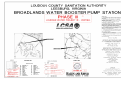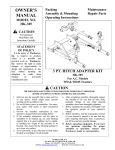
1
Broadlands Water Booster Pump Station Phase III Upgrade Request for Quote December 22, 2011 Request For Quote RFQ 2011 018 200 December 22, 2011 BROADLANDS WATER BOOSTER PUMPING STATION PHASE III UPGRADE Quote Loudoun Water, the Owner, is soliciting quotes (Quotes) from Contractors (Bidders) for the Project known as “Broadlands Water Booster Pumping Station Phase III Upgrade” (Project). Bidders shall complete the attached Quote Form and submit their Quote either electronically to [email protected] or in a sealed envelope to: Loudoun Water 44865 Loudoun Water Way Ashburn, VA 20147 571-291-7700 ATTN: Jack Jadryev RFQ 2011 018 200 Quotes are due by 3:00 pm on February 2, 2012. This solicitation is informal; the Quotes will not be read aloud, and will not be publicly announced. The Contract, if awarded, will be to the lowest responsive, responsible Bidder. Project Site The site of the Project (Site) is at 12270 Belmont Ridge Road, Ashburn, Virginia. Project Description The Project includes mechanical and electrical work at an existing water booster pumping station located inside the Broadlands Elevated Water Storage Tank #2, including, but is not limited to, the following: • replacing two existing horizontal mounted 10 HP constant speed pumps with two new 15 HP vertical mounted pumps with variable frequency drives (VFD) • installing a manual transfer switch and a generator receptacle on the outside of the tank All new and modified equipment and piping shall be painted to match the existing piping and equipment. A one year warranty is required for all work completed as part of the Project. The Contractor shall test and make fully operational all pumping equipment, complete with all necessary accessories. Contractor shall be responsible for coordinating between pump supplier and VFD supplier to ensure a complete and operational system. The terms “Work” and “Project” are used synonymously through this document. The entire scope of the Project can be found on the Contract Documents which are attached hereto for your use. Loudoun Water Project ID#: 20070164 Page 2 of 14 BROADLANDS WBPS PHASE III RFQ 2011-018-200 Site Visit (optional) The Owner will conduct a Site visit on January 5, 2012 at 10:00 am. Interested Bidders are urged to attend, though attendance is not mandatory for Bidders to submit a Quote. Bidders interested in scheduling a Site visit should contact Jack Jadryev at 571-291-7975. Questions Concerning this Quote All questions concerning this Quote shall be submitted in writing at least seven day prior to the date Quotes are due. Bidders may email their questions to [email protected] or fax them to 571-223-1527, Attention: Jack Jadryev. Any changes to the Contract Documents prior to the date that Quotes are due shall be made only by addenda issued by Loudoun Water. Quote Form All Quotes shall be submitted on the enclosed Quote Form. Bidders shall complete the Quote Form completely for the Quote to be considered responsive. Payment Terms Loudoun Water will make partial payments for the Work on a monthly basis upon receipt of Contractor’s invoice for Work performed during the month. The Contractor shall submit a final release of liens and claims with the final invoice. Contract Time The Contractor shall complete the Work within 120 days of the issuance of Notice to Proceed. This period of performance (Contract Time) may be adjusted only by change order issued by the Owner. Contract Documents Contract Documents consist of: 1. this solicitation, 2. Quote Form, 3.Loudoun Water’s Standard Terms and Conditions, 4.Pump and Motor data sheets, 5. Contract Specifications (see attachments), 6. Contract Drawings (including Cover Sheet, M1, E1, E2, and E3) prepared by Hazen and Sawyer (work items are indicated in red), and 7. Loudoun Water’s engineering design manual (available online). Any changes to the Contract Documents after award of the Contract shall be included in a change order. General Terms and Conditions Loudoun Water’s Standard Terms and Conditions shall govern the procurement and administration of the Contract. Additionally, the Contractor shall be responsible for securing all permits required for the Project. Loudoun Water’s Engineering Design Manual (EDM), includes a “Standard Details” and an “Approved Materials List” which catalogs manufacturers and products approved for use in Loudoun Water’s system. Unlisted items are not approved for use. Loudoun Water’s EDM may be reviewed and/or downloaded at the following website: http://www.loudounwater.org/Developers-and-New-Construction/Engineering-Design-Manual/ Loudoun Water Project ID#: 20070164 Page 3 of 14 BROADLANDS WBPS PHASE III RFQ 2011-018-200 Coordination and Specific Conditions The Contractor shall cooperate and coordinate with Loudoun Water and other contractors to allow the work of both contracts to proceed concurrently and allow the Owner to operate and maintain the water booster pump station during construction. One booster pump (either new or existing) shall remain in service at all times during construction. Liquidated Damages If the Contractor does not complete the Work within the Contract Time, Liquidated Damages, in the amount of $500 per day, will be assessed for every calendar day beyond the Contract Time until the Contractor completes the Work. Bidders Declarations By submitting a Quote, Bidder declares the following: 1. The Quote is submitted in good faith and without fraud, and that it is made without collusion with any official of the Owner; 2. The Bidder has carefully examined the Contract Documents, and addenda (if any) for the construction of the Work; 3. The Bidder has inspected the Site and is satisfied regarding to the quantities including material, equipment, and conditions of the Work involved; and 4. The Contract Time is reasonable for the performance of the Work. Attachments Contract Drawings (Cover Sheet, M1, E1, E2, and E3) Pump and Motor Data Sheet, consisting of 3 pages Document 01640 – Training, consisting of 6 pages Document 01650 – Field Testing and Startup Requirements, consisting of 10 pages Document 16495 - Variable Frequency Drive System, consisting of 19 pages Loudoun Water Project ID#: 20070164 Page 4 of 14 BROADLANDS WBPS PHASE III RFQ 2011-018-200 QUOTE FORM Project Name: Broadlands Water Booster Pumping Station Phase III Upgrade LCSA Project ID#: 20070164 RFQ #: 2011-018-200 Quote To Owner: Loudoun County Sanitation Authority (DBA Loudoun Water) 44865 Loudoun Water Way Ashburn, Virginia 20147 (571) 291-7700 [email protected] Bidder’s Address: Print Name of Contact Person: Phone Number: In compliance with the OWNER'S Request for Quote, BIDDER hereby proposes to perform all WORK for the construction of the “Broadlands Water Booster Pumping Station Phase III Upgrade Project ID No. 20070164” in strict accordance with the CONTRACT DOCUMENTS, within the time set forth therein, and at the prices stated below. By submission of the QUOTE, each BIDDER certifies, and in the case of a joint QUOTE each party thereto certifies as to his own organization, that this QUOTE has been arrived at independently, without consultation, communication, or agreement as to any matter relating to this QUOTE with any other BIDDER or with any competitor. BIDDER hereby agrees to commence work under this contract, on or before a date to be specified in the NOTICE TO PROCEED and to complete the PROJECT within 120 consecutive calendar days thereafter. BIDDER acknowledges receipt of the following ADDENDUM: No. , Date No. , Date No. , Date Loudoun Water Project ID#: 20070164 Page 5 of 14 BROADLANDS WBPS PHASE III RFQ 2011-018-200 Total Lump Sum Quote Price The BIDDER agrees to perform all work described in the Request for Quote and Contract Documents of the Broadlands Water Booster Pumping Station Phase III Upgrade Project ID No. 20070164 for the following Total Lump Sum Price: Contract Item No. Estimated Quantity Description of Work Price in Words 1 Lump Sum Price in Numbers Total Lump Sum Base Quote: $______________ ____________________________________________ ____________________________________________ ____________________________________________ ______________________ Dollars __________ Cents Respectfully Submitted: Signature Address Title Date Virginia License No. Federal Employer’s Identification No. SEAL (if Quote is by a Corporation) ATTEST: Any contractor submitting a Quote on this project hereby certifies that he has the proper contractor's license and meets all the qualifications required by the statutes of the State and subdivision in which the work is to be performed. Date Loudoun Water Project ID#: 20070164 Signature Page 6 of 14 BROADLANDS WBPS PHASE III RFQ 2011-018-200 BIDDER DATA SHEET BROADLANDS WATER BOOSTER PUMPING STATION PHASE III UPGRADE RFQ 2011 018 200 Note: The following information is required as part of your response to this solicitation. The Bidder shall have the capability and capacity in all respects to satisfy fully all of the contractual requirements. Failure to complete and provide this sheet may result in finding your proposal nonresponsive. Bidder’s Primary Contact: Name: Email: Phone No Fax No Indicate below a listing of at least four (4) current or recent projects, preferable water/wastewater accounts and/or governmental, that your company is servicing, has serviced, or has provided similar services. Include the length of service and the name, address, and telephone number of the point of contact and a brief description of the project: A. Firm Name Mailing Address Contact Phone No. Email Address Contract Amount $ Description of Work Performed B. Title Fax No. Contract Dates Firm Name Mailing Address Contact Phone No. Email Address Contract Amount $ Description of Work Performed C. Title Fax No. Contract Dates Firm Name Mailing Address Contact Phone No. Email Address Contract Amount $ Description of Work Performed D. Title Fax No. Contract Dates Firm Name Mailing Address Contact Phone No. Email Address Contract Amount $ Description of Work Performed Loudoun Water Project ID#: 20070164 Title Fax No. Contract Dates Page 7 of 14 BROADLANDS WBPS PHASE III RFQ 2011-018-200 Loudoun Water Contract - Standard Terms and Conditions A. Procedures The extent and character of the services to be performed by the Bidder (Contractor) shall be subject to the general control and approval of Loudoun Water’s General Manager or his authorized representative. Any change to the contract must be approved in writing by the Manger of Procurement and Risk and the Contractor. The Contractor is prohibited from assigning, transferring, conveying, subletting, or otherwise disposing of this agreement or its rights, title or interest therein or its power to execute such agreement to any other person, company or corporation without the prior consent and approval in writing by Loudoun Water. B. Contract Period The contract period, also known as Contract Time, is defined as 120 days commencing on the date specified in the Notice to Proceed. The Contract Time shall be changed only by Change Orders. C. Invoicing and Payment The firm shall submit invoices for each deliverable (by project), to include a detailed breakdown of all charges. Invoices shall be based upon completion of tasks or deliverables and shall include progress reports. All such invoices will be paid promptly by Loudoun Water unless any items thereon are questioned, in which event payment will be withheld pending verification of the amount claimed and the validity of the claim. The firm shall provide complete cooperation during any such investigation. All invoices shall reference the Purchase Order and shall be forwarded to the following address: Loudoun Water Attn: Accounts Payable 44865 Loudoun Water Way Ashburn, VA 20147 Individual Contractors shall provide their social security numbers, and proprietorships, partnerships, and corporations shall provide their federal employer identification number on the pricing form. D. Payments to Subcontractors 1. Within seven days after receipt of amounts paid by Loudoun Water for work performed by a subcontractor under this contract, the Contractor shall either: a. Pay the Subcontractor for the proportionate share of the total payment received from Loudoun Water attributable to the work performed by the Subcontractor under this contract; or b. Notify Loudoun Water and Subcontractor, in writing, of his intention to withhold all or a part of the Subcontractor's payment and the reason for non- payment. Loudoun Water Project ID#: 20070164 Page 8 of 14 BROADLANDS WBPS PHASE III RFQ 2011-018-200 2. The Contractor shall pay interest to the Subcontractor on all amounts owed that remain unpaid beyond the seven day period except for amounts withheld as allowed in item b. above. 3. The Contractor shall include in each of its subcontracts a provision requiring each Subcontractor to include or otherwise be subject to the same payment and interest requirements as set forth above with respect to each lower-tier subcontractor. 4. The Contractor's obligation to pay an interest charge to a Subcontractor pursuant to this provision may not be construed to be an obligation of Loudoun Water. E. Ethics in Public Contracting 1. The provisions contained in Sections 2.2-4367 through 2.2-4377 of the Virginia Public Procurement Act as set forth in the 1950 Code of Virginia, as amended, shall be applicable to all contracts solicited or entered into by Loudoun Water. 2. The above-stated provisions supplement, but do not supersede, other provisions of law including, but not limited to, the Virginia State and Local Government Conflict of Interest Act (Section 2.2-3100 et seq.), the Virginia Governmental Frauds Act (Section 18.2498.1 et seq.) and Articles 2 and 3 of Chapter 10 of Title 18.2. The provisions apply notwithstanding the fact that the conduct described may not constitute a violation of the Virginia State and Local Government Conflict of Interests Act. F. Delays If delay is foreseen Contractor shall give thirty (30) days prior written notice to the Division of Procurement. Loudoun Water has the right to extend delivery date if reasons appear, in the sole discretion of Loudoun Water, to be valid. Contractor must keep Loudoun Water advised at all times of status of order. Default in promised delivery (without accepted reasons) or failure to meet specifications, authorizes the Division of Procurement to purchase supplies, equipment or services elsewhere and charge full increase in cost and handling to defaulting Contractor. G. Notice of Required Disability Legislation Compliance 1. Loudoun Water is required to comply with state and federal disability legislation: The Rehabilitation Act of 1973 Section 504, The Americans with Disabilities Act (ADA) for 1990 Title II and The Virginians with Disabilities Act of 1990. 2. Specifically, Loudoun Water may not, through its contractual and/or financial arrangements, directly or indirectly avoid compliance with Title II of the Americans with Disabilities Act, Public Law 101-336, which prohibits discrimination on the basis of disability by public entities. Subtitle A protects qualified individuals with disability from discrimination on the basis of disability in the services, programs, or activities of all State and local governments. It extends the prohibition of discrimination in federally assisted programs established by the Rehabilitation Act of 1973 Section 504 to all activities of State and local governments, including those that do not receive Federal financial assistance, and incorporates specific prohibitions of discrimination on the basis of disability in Titles I, III, and V of the Americans with Disabilities Act. The Virginians with Disabilities Act of 1990 follows the Rehabilitation Act of 1973 Section 504. Loudoun Water Project ID#: 20070164 Page 9 of 14 BROADLANDS WBPS PHASE III RFQ 2011-018-200 H. Immigration Reform and Control Act of 1986 By entering this Contract, the Contractor certifies that it does not and will not during the performance of this Contract violate the provisions of the Federal Immigration Reform and Control Act of 1986, which prohibits employment of illegal aliens. I. Insurance The Contractor shall procure, maintain, and provide proof of insurance coverages for injuries to persons and/or property damage as may arise from or in conjunction with, the work performed on behalf of Loudoun Water by the Contractor, his agents, representatives, employees or subcontractors. Proof of coverage as contained herein shall be submitted fifteen (15) days prior to the commencement of work and such coverage shall be maintained by the Contractor for the duration of the contract period; for occurrence policies. Claims made policies must be in force or that coverage purchased for three (3) years after contract completion date. 1. General Liability Coverage shall be as broad as: Comprehensive General Liability endorsed to include Broad Form, Commercial General Liability form including Products/Completed Operations. a. Minimum Limits General Liability: i. $1,000,000 General Aggregate Limit ii. $1,000,000 Products & Completed Operations iii. $1,000,000 Personal and Advertising Injury iv. $1,000,000 Each Occurrence Limit v. $50,000 Fire Damage Limit vi. $5,000 Medical Expense Limit 2. Automobile Liability Coverage sufficient to cover all vehicles owned, used, hired, or non-owned by the Contractor, his agents, representatives, employees or subcontractors. a. Minimum Limits Automobile Liability: i. $1,000,000 Combined Single Limit ii. Statutory Uninsured Motorist Coverage iii. $1,000,000 Each Occurrence Limit iv. $5,000 Medical Expense Limit 3. Workers' Compensation a. Limits as required by the Workers' Compensation Act of Virginia. b. Employers Liability, $1,000,000 c. Compliance with all Federal Statutes, including U.S. Longshoreman and Harbor Worker’s Act, the Jones Act, and Federal Employee Act. 4. Coverage Provisions a. All deductibles or self-insured retention shall appear on the certificate(s). b. Loudoun Water, its' officers/ officials, employees, agents and volunteers shall be added as "additional insured" as their interests may appear. This provision does not apply to Professional Liability or Workers' Compensation/Employers' Liability. Loudoun Water Project ID#: 20070164 Page 10 of 14 BROADLANDS WBPS PHASE III RFQ 2011-018-200 c. The Contractor's insurance shall be primary over any applicable insurance or selfinsurance maintained by Loudoun Water. d. Shall provide 30 days written notice to Loudoun Water before any cancellation, suspension, or void of coverage in whole or part, where such provision is reasonable. e. All coverages for subcontractors of the Contractor shall be subject to all of the requirements stated herein. f. All deductibles or self-insured retention shall appear on the certificate(s) and shall be subject to approval by Loudoun Water. At the option of Loudoun Water, either; the insurer shall reduce or eliminate such deductible or self-insured retention; or the Contractor shall be required to procure a bond guaranteeing payment of losses and related claims expenses. g. Failure to comply with any reporting provisions of the policy(s) shall not affect coverage provided Loudoun Water, its' officers/officials, agents, employees and volunteers. h. The insurer shall agree to waive all rights of subrogation against Loudoun Water, its' officers/officials, agents, employees or volunteers for any act, omission or condition of premises which the parties may be held liable by reason of negligence. i. The Contractor shall furnish Loudoun Water certificates of insurance including endorsements affecting coverage. The certificates are to be signed by a person authorized by the insurance company(s) to bind coverage on its' behalf, if executed by a broker, notarized copy of authorization to bind, or certify coverage must be attached. j. All insurance shall be placed with insurers maintaining an A.M. Best rating of no less than an A:VII. If A.M. Best rating is less than A:VII, approval must be received from Loudoun Water’s Manger of Procurement and Manager. k. All coverages designated herein shall be as broad as the Insurance Services Office (ISO) forms filed for use with the Commonwealth of Virginia. J. Safety All contractors and subcontractors performing services for Loudoun Water are required and shall comply with all Occupational Safety and Health Administration (OSHA), State and County Safety and Occupational Health Standards and any other applicable rules and regulations. Also all contractors and subcontractors shall be held responsible for the safety of their employees and any unsafe acts or conditions that may cause injury or damage to any persons or property within and around the work site area under this contract. K. Rider Clause The Contractor shall, during the term of the contract, extend to any authority, department, agency or institution of the Commonwealth of Virginia the ability to acquire goods and services, other than professional services, at contract prices in accordance with contract terms. L. Hold Harmless Clause The Contractor shall, during the term of the contract including any warranty period, indemnify, defend, and hold harmless Loudoun Water, its officials, employees, agents, and representatives thereof from all suits, actions, or claims of any kind, including attorney's fees, brought on account of any personal injuries, damages, or violations of rights, sustained by any person or property in consequence of any neglect in safeguarding contract work or on account of any act or omission by the Contractor or his employees, or from any claims or amounts arising from violation of any law, bylaw, ordinance, regulation or decree. Loudoun Water Project ID#: 20070164 Page 11 of 14 BROADLANDS WBPS PHASE III RFQ 2011-018-200 The Contractor agrees that this clause shall include claims involving infringement of patent or copyright. M. Not To Benefit As a prerequisite for payment pursuant to the terms of this contract, there shall be furnished to Loudoun Water a statement, that no employee of Loudoun Water, or members of his immediate family, including spouse, parents or children has received or has been promised, directly or indirectly, any financial benefit, by way of fee, commission, finder's fee or in any other manner, remuneration arising from or directly or indirectly related to a contract resulting from this RFP. N. Licensure: To the extent required by the Commonwealth of Virginia (see e.g. 54.1-1100 et seq. of the Code of Virginia), the Contractor shall be duly licensed to perform the services required to be delivered pursuant to any resulting agreement. O. Exemption from Taxes Loudoun Water is exempt from State and Federal Taxes. Tax Exemption Certificate indicating Loudoun Water's tax exempt status will be furnished by Loudoun Water on request. P. Substitutions NO substitutions, including key personnel, or cancellations permitted after award without written approval by the Manager of Procurement and Risk and Loudoun Water’s General Manager. Q. Assignment of Contract This contract may not be assigned in whole or in part without the written consent of the Manager of Procurement and Risk. R. Termination Subject to the provisions below, the contract may be terminated by Loudoun Water upon thirty (30) days advance written notice to the other party; but if any work or service hereunder is in progress, but not completed as of the date of termination, then this contract may be extended upon written approval of Loudoun Water until said work or services are completed and accepted. 1. Termination for Convenience In the event that this contract is terminated or canceled upon request and for the convenience of Loudoun Water, without the required thirty (30) days advance written notice, then Loudoun Water shall negotiate reasonable termination costs, if applicable. 2. Termination for Cause Termination by Loudoun Water for cause, default or negligence on the part of the Firm shall be excluded from the foregoing provision; termination costs, if any, shall not apply. The thirty (30) days advance notice requirement is waived in the event of Termination for Cause. 3. Termination Due to Unavailability of Funds in Succeeding Fiscal Years When funds are not appropriated or otherwise made available to support continuation of performance in a subsequent fiscal year, the contract shall be canceled and the contractor Loudoun Water Project ID#: 20070164 Page 12 of 14 BROADLANDS WBPS PHASE III RFQ 2011-018-200 shall be reimbursed for the reasonable value of any non-recurring costs incurred but not amortized in the price of the supplies or services delivered under the contract. S. Contractual Disputes The Contractor shall give written notice to the Manager of Procurement and Risk of his intent to file a claim for money or other relief at the time of the occurrence or the beginning of the work upon which the claim is to be based. The written claim shall be submitted to the Manager of Procurement and Risk no later than sixty (60) days after final payment. If the claim is not disposed of by agreement, the Manager of Procurement and Risk shall reduce her decision to writing and mail or otherwise forward a copy thereof to the Contractor within thirty (30) days of receipt of the claim. The Manager of Procurement and Risk’s decision shall be final unless the Contractor appeals within thirty (30) days by submitting a written letter of appeal to the General Manager, or his designee. The General Manager shall render a decision within sixty (60) days of receipt of the appeal. T. Severability In the event that any provision shall be adjudged or decreed to be invalid, such ruling shall not invalidate the entire Agreement but shall pertain only to the provision in question and the remaining provisions shall continue to be valid, binding and in full force and effect. U. Applicable Laws This contract shall be governed in all respects by the laws of the Commonwealth of Virginia. V. Employment Discrimination by Contractors Prohibited Every contract over $10,000 shall include the following provisions: During the performance of this contract, the Contractor agrees as follows: 1. The Contractor will not discriminate against any employee or applicant for employment because of race, religion, color, sex, national origin, age or disability, or any other basis prohibited by state law relating to discrimination in employment, except where there is a bona fide occupational qualification reasonably necessary to the normal operation of the Contractor. The Contractor agrees to post in conspicuous places, available to employees and applicants for employment, notices setting forth the provisions of this nondiscrimination clause. 2. The Contractor, in all solicitations or advertisements for employees placed by or on behalf of the Contractor, shall state that such Contractor is an equal opportunity employer. 3. Notices, advertisements and solicitations placed in accordance with federal law, rule or regulation shall be deemed sufficient to meet this requirement. 4. The Contractor will include the provisions of the foregoing paragraphs, 1, 2, and 3 in every subcontract or purchase order over $10,000 so that the provisions will be binding upon each subcontractor or vendor. Loudoun Water Project ID#: 20070164 Page 13 of 14 BROADLANDS WBPS PHASE III RFQ 2011-018-200 W. Drug-free Workplace Every contract of over $10,000 shall include the following provisions: During the performance of this contract, the Contractor agrees to (i) provide a drug-free workplace for the Contractor’s employees; (ii) post in conspicuous places, available to employees and applicants for employment, a statement notifying employees that the unlawful manufacture, sale, distribution, dispensation, possession, or use of a controlled substance including marijuana is prohibited in the Contractor’s workplace and specifying the actions that will be taken against employees for violations of such prohibition; (iii) state in all solicitations or advertisements for employees placed by or behalf of the Contractor that the Contractor maintains a drug-free workplace; and (iv) include the provisions of the foregoing clauses in every subcontract or purchase order over $10,000 so that the provisions will be binding upon each subcontractor or vendor. For the purpose of this section, “drug-free workplace” means a site for the performance of work done in connection with a specific contract awarded to an Contractor in accordance with this chapter, the employees of whom are prohibited from engaging in the unlawful manufacture, sale, distribution, dispensation, possession, or use of a controlled substance including marijuana during the performance of the contract. Loudoun Water Project ID#: 20070164 Page 14 of 14 BROADLANDS WBPS PHASE III RFQ 2011-018-200 Pump and Motor Data Sheet Patterson Vertical In-Line Close Coupled HVAC Pump – No “or equals” or substitutes will be accepted Model V4B11A-CC CW Rotation Impeller Dia.: 10.0625” Pump Size: 4X4X11 Rated RPM: 1770 475 GPM TDH Calculated Efficiency @ Duty Point: 73% Break HP: 12.92 Non Overloading HP: 14.7 NPSHR (feet): 14.4 Maximum Pump Working Pressure: 175# Motor: 60 HZ - 208V, 15 HP, ODP-PE, NEMA Design B Baldor Model #: EJMM2513T Options – Pump to include 416 stainless steel shaft Motor to include 120 VAC winding space heaters and the stator shall be equipped with six (6) thermistor resistance temperature detectors (RTD’s) embedded in the end coils of the stator winding (2 RTD’s per stator phase). Owner will not be present for factory hydrostatic and performance tests. Five (5) certified copies of the manufacturer's actual test data and interpreted results thereof, shall be submitted for review. No such equipment shall be shipped to the project until the Engineer has been furnished a certified copy of test results and has notified the Contractor, in writing, that the results of such tests are acceptable. Pumps shall be certified to be free from excessive vibration, cavitation, noise, and oil or water leaks. Vibration shall not exceed the Acceptable Peak to Peak Displacement per Frequency shown on Figure 75 for “Rigid Structures” of the Hydraulic Institute Standards. Pump nameplates shall include a minimum of three design capacity and total dynamic head points, which correspond to the factory tested capacity of the pump at the time of manufacture. Field testing, startup and Reliability/Demonstration Testing are prerequisites to Substantial Completion and, therefore, shall be completed within the time specified for Substantial Completion. Pumps shall be provided complete with all accessories, shims, couplings, fasteners, lubricants, pump base and other appurtenances as specified, and as may be required for a complete and operating unit. The Contractor shall furnish and install pressure gauges with diaphragm-type isolation seals on the suction and discharge of each pump. • • Suction gauges shall be Ashcroft Duralife Model 1009 3-1/2” liquid-filled gauges with stainless steel case, ¼” NPT, lower stem mount type, ±1% full scale accuracy, stainless steel bourdon tube pressure element and stainless steel, Teflon coated pinion gear and segment movement with a range of 0 to 100 psi. Discharge gauges shall be Ashcroft Duralife Model 1009 3-1/2” liquid-filled gauges with stainless steel case, ¼” NPT, lower stem mount type, ±1% full scale accuracy, Pump and Motor Data Sheet Page 1 of 3 • stainless steel bourdon tube pressure element and stainless steel, Teflon coated pinion gear and segment movement with a range of 0 to 200 psi. A ¼” isolation stainless steel ball valve and an Ashcroft All Welded “Mini” Diaphragm Seal Type 310, shall be provided for each gauge assembly. All gland seals, air valves, and drains shall be piped to the nearest floor drain or trench drain with galvanized steel pipe or copper tube, properly supported with brackets. One set of spare parts shall be provided including: Set of Gaskets and O-Ring Seals One Mechanical Shaft Seal Assembly One Casing Wear Ring One Impeller One Shaft Sleeve Five Tubes of Manufacturer Suggested Bearing Lubrication Grease Pump and Motor Data Sheet Page 2 of 3 Pump Data Sheet - Patterson HVAC Pumps Company: LCSA - Jack Jadryev Name: Red Dot 19C - Inline Date: 2/15/2011 Pump: Search Criteria: Model: V4B11A-CC Flow: 475 US gpm Type: VIL Synch speed: 1800 rpm Speed: 1770 rpm Dia: 10.0625 in Size: 4x4x11 Impeller: D05-90019 Specific Speeds: Ns: 1064 Nss: 5492 Dimensions: Suction: 4 in Discharge: 4 in Head: 80 ft Fluid: Water SG: 1 Viscosity: 1.105 cP Temperature: 60 °F Vapor pressure: 0.2563 psi a Atm pressure: 14.7 psi a NPSHa: --Motor: Standard: NEMA Enclosure: ODP Size: 15 hp Speed: 1800 Frame: See Chart Sizing criteria: Max Power on Design Curve Pump Limits: Temperature: --Pressure: --Sphere size: --- Power: --Eye area: --- ---- Data Point ---Flow: 475 US gpm Head: 80.6 ft Eff: 73.8% Power: 13.1 hp NPSHr: 14.4 ft 140 11 in Shutoff dP: 47.1 psi Min flow: 97.5 US gpm BEP: 7576 79 10.0625 in 79 76 75 77.1 100 70 Head - ft 109 ft 70 120 ---- Design Curve ---Shutoff head: 50 55 60 65 77.1% @ 390 US gpm NOL power: 14.7 hp @ 614 US gpm 65 80 8.5 in 60 50 55 60 65 55 70 60 50 -- Max Curve -70 Max power: 20.1 hp @ 658 US gpm 25 hp 65 40 60 55 50 NPSHr - ft 15 hp 10 hp 20 0 30 20 hp 7.5 hp 100 200 300 400 500 600 700 800 100 200 300 400 500 600 700 800 20 10 0 US gpm Refer to Working Pressure vs. Temperature chart for maximum rated working pressure. All data are subject to change. Contact factory for certified data. Performance Evaluation: Flow US gpm Speed rpm Head ft Efficiency % Power hp NPSHr ft 570 1770 59.6 60.4 14.2 18.4 475 1770 80.6 73.8 13.1 14.4 380 1770 93.8 76.8 11.7 11.3 285 1770 101 72.7 9.99 8.69 190 1770 105 56.4 8.92 6.8 Page 3 of 3 Selected from catalog: Patterson HVAC.60 Vers: 1.2 SECTION 01640 TRAINING REQUIREMENTS PART I - GENERAL 1.01 A. 1.02 SECTION INCLUDES Training of the Owner’s operations personnel on the proper care, maintenance and operation of the equipment. Also included are the preparation of lesson plans and training aids and the required qualifications for instructors. THE REQUIREMENTS A. Provide the services of qualified factory trained representatives of the equipment manufacturers for all equipment furnished under this Contract, who shall provide operations and maintenance training. B. Training shall be completed before Reliability/Demonstration Testing and after field testing & start-up. Training shall not be conducted earlier than sixty (60) days prior to Substantial Completion. Training shall not be conducted on the same day as field testing and start-up services as specified in Field Testing and Startup. C. Operation and Maintenance Manuals are required to be approved prior to beginning training. 1.03 A. 1.04 A. SUBMITTALS The Contractor shall submit the following items as and when specified in this Section: 1. Lesson Plans 2. Instructor Qualifications 3. Training Aids TRAINING The training shall consist of both field instruction and classroom instruction. 1. Field instruction is the Owner’s preference and is to be “hands on type training” conducted at the equipment installations. Field training shall identify the location and proper use and function of any valves, pushbuttons, control panels, switches, and other similar equipment required for operation. Field training shall also identify the location and proper use and function of any maintenance equipment such as grease fittings, oilers, isolation valves, safety lockout switches, and other similar equipment. 2. Classroom instruction shall consist of equipment component theory of operation, start-up and shutdown, safety, troubleshooting and routine maintenance training best presented in a classroom environment and as approved by the Owner. Loudoun Water Project#: 20070164 01640-1 BROADLANDS WBPS PHASE III 9/30/2011 B. All field training shall take place at the project site or at an alternate location approved by the Owner. All classroom training shall take place at the Owner’s Operation and Maintenance Facility located in Ashburn, Virginia. C. Training sessions shall be conducted between the hours of 8:00 a.m. and 4:00 p.m. D. For each piece of equipment, up to three (3) training sessions shall be conducted for up to 10 people per session for a time period as specified and as appropriate for each equipment/system. E. Schedule training sessions with the Owner and the Engineer, providing a minimum of fourteen (14) days prior notice of training, subject to the approval of the Engineer and the Owner. F. Videotaping G. 1. The Owner reserves the right to videotape all manufacturers’ training. 2. The manufacturer may offer prerecorded videotape(s) covering the equipment supplied. If prerecorded videotape(s) are provided, the Owner shall have the right to permanent ownership and use of at least two complete copies. Lesson Plans: Submit lesson plans that include specific information about each item of equipment or equipment system, including controls. 1. Submit lesson plans for approval by the Engineer no less than sixty (60) days prior to the date of the proposed training. 2. The lesson plans shall indicate when training aids are used or referred to during the course of instruction. 3. Outline of lesson plan a. b. c. Loudoun Water Project#: 20070164 Equipment Description (1) Purpose and function of equipment and auxiliary equipment and systems. (2) Physical arrangement of equipment components and electrical supply. (3) General function of controls, including automatic and manual operation, interlocks, and shutdowns. Equipment Operation (1) Operating requirement for equipment to perform satisfactorily. (2) Typical operating characteristics. (3) Start-up and shutdown procedures. (4) Use of controls. Equipment Monitoring (1) Recommended routine instrument readings and operational checking. (2) Early warning signs of developing operational or equipment problems. 01640-2 BROADLANDS WBPS PHASE III 9/30/2011 (3) Description of the facilities Supervisory Control and Data Acquisition (SCADA) System d. Equipment operational troubleshooting procedures. e. Safety and Housekeeping (1) Safety features of the equipment. (2) Safe work practices. (3) Housekeeping practices. f. Description of the use of the equipment manufacturer's Operations and Maintenance Manual (O&M Manual) in regards to operation. g. Preventive Maintenance Requirements h. i. (1) Maintenance needs for equipment. (2) Identification of procedure to satisfy maintenance need (relate to equipment manufacturer's O&M Manual, which should have detailed descriptions of maintenance procedures). (3) Outline or summarize procedures. (4) Recommended schedule for performing preventive maintenance. (5) Provide preventive maintenance record forms (if available). Maintenance Inspection Program (1) Parts, components, and areas of equipment to inspect for routine preventive maintenance. (2) Recommended frequency of inspection. (3) Inspection procedures. (4) Problem identification. Maintenance Troubleshooting (1) Sections in O&M Manual detailing troubleshooting procedures. (2) Summarize troubleshooting procedures. (3) Testing equipment used in troubleshooting. (4) j. Loudoun Water Project#: 20070164 (a) Demonstration use of specialized testing equipment if supplied with equipment. (b) Other testing equipment. Tests used to verify troubleshootings findings. Disassembly and Assembly (1) Summarize disassembly and assembly procedures. (2) O&M Manual coverage of subject. (3) Testing to verify success of corrective maintenance. 01640-3 BROADLANDS WBPS PHASE III 9/30/2011 k. H. (1) Calibration needs and tolerances. (2) Calibration equipment. (3) O&M Manual listing of calibration ranges, tolerances and settings. Training Aids: Training aids shall be provided by the Contractor as required as an integral part of the training program. 1. 2. 3. I. Equipment Calibration Training aids shall include text and/or pictorial handouts specific to the equipment supplied. a. Submit a copy of the training aids (text and/or pictorial handouts) for approval by the Engineer no less than sixty (60) days prior to the date of the proposed training. b. Handouts shall be legible and printed on good quality stock. c. Final handouts shall be provided with lesson plans to each trainee at the time of training. d. Sufficient quantity of final (accepted) handouts for each attendee (trainee) shall be provided by the Contractor. Additional training aids specific to the facility/system shall be used for maximum training effectiveness and shall include the following as appropriate: a. Audio visual aids, for example: films, videotapes, slides, overhead transparencies, posters, blueprints, diagrams, and catalog sheets. b. Models and samples, for example: cutaways, spare parts, tools, miniature models, equipment assemblies, and damaged parts. c. Training equipment (laptops, projectors, screens, etc.) shall be provided by the Contractor. The use of additional training aids shall be identified in the lesson plan, and a description of the additional final (accepted) training aids shall be provided by the Contractor. Qualifications 1. Submit documentation showing the qualifications of the proposed training specialists (instructor) for approval by the Engineer no less than sixty (60) days prior to the date of the proposed training. Refer to Attachment A for an example of Statement of Instructor Qualifications form. The documentation shall include the following: a. Experience of the training specialists in operation and maintenance of the equipment; b. A Statement of Instructor Qualifications; c. References for previous training on the equipment, including project names, contact names, and phone numbers. 2. The training specialist must be knowledgeable of the equipment’s application specific to this project. Loudoun Water Project#: 20070164 01640-4 BROADLANDS WBPS PHASE III 9/30/2011 3. Only those training specialists whose qualifications have been approved by the Owner shall conduct training. J. Coordinate training services with the Owner, the Engineer, and Manufacturer. K. Deliver all training materials to the Owner at least fourteen (14) days prior to scheduled training. L. The Contractor shall coordinate and verify to ensure prior to the scheduled training times: 1. That all associated construction required to operate the equipment in all normal and anticipated operating modes is complete and that the equipment is ready to be used for training purposes. 2. That the equipment area is well lit and unobstructed so that all training class attendees may access, view and hear the training. 3. That the equipment area is free of construction activities that could present a hazard to training class participants. M. During the training, as provided in the “Training Schedule” below, the Owner reserves the right to cancel unsatisfactory training at any time. Contractor will be required to reschedule make-up training (at no additional cost to the Owner), at a schedule approved by the Owner. TRAINING SCHEDULE SPECIAL SECTION EQUIPMENT Vertical Close Coupled Pumps Control & Information Systems Operator Training (Para 1.05) Maintenance Training (Para 1.06) Instrument Training (Para 1.07) General Refresher (Para 1.08) NO. OF SESSIONS 3 HOURS/ SESSION 2 2 2 1 1 4 4 2 8 PART 2 - PRODUCTS (NOT USED) PART 3 - EXECUTION (NOT USED) - END OF SECTION - Loudoun Water Project#: 20070164 01640-5 BROADLANDS WBPS PHASE III 9/30/2011 Attachment A STATEMENT OF INSTRUCTOR QUALIFICATIONS TRAINING INSTRUCTOR NAME: Vendor Package: Technical Specification Name and Number: Staged Demonstration Included (Y/N) Equipment Trainees: # of Groups Factory and/or Equipment Training: Type of Training and Dates Attended: Type of Training Training Provider # of Sessions Dates Attended Record of Work Experience Related to Equipment Employer Name/Address Job Title and Duties Dates Employed Record of Training and Instructional Experience Job Title/Duties/Type of Employer Name/Address Training Provided/Audience Dates Employed Project Training References Project Name: Project 1 Project 2 Location: Contact Person Name: Contact Telephone: Contact Person's Role During Project: Dates of Training: Duties/Type of Training Provided: Loudoun Water Project#: 20070164 01640-6 BROADLANDS WBPS PHASE III 9/30/2011 SECTION 01650 FIELD TESTING AND STARTUP REQUIREMENTS PART 1 -- GENERAL 1.01 A. 1.02 A. SECTION INCLUDES Field Testing and Startup activities shall comprise a phased approach for accomplishing equipment and systems checkout, verification of operation and reliability/demonstration testing as described herein. THE REQUIREMENTS Provide the services of qualified factory trained representatives of the equipment manufacturers for all equipment furnished under this Contract, who shall provide the following services: 1. Supervise and assist in the installation of the equipment to ensure proper installation 2. Check the installation of the equipment and make all necessary adjustments prior to testing. 3. Supervise the equipment and system field tests and startup as described herein. 4. Provide additional manufacturer services as specified in each relevant equipment and system specification section in addition to the services specified herein. B. Provide Field Testing and Startup in compliance with the specified requirements. Approval of the field test results is a prerequisite for obtaining full payment for the equipment furnished. C. Field testing, startup and Reliability/Demonstration Testing are prerequisites to Substantial Completion and, therefore, shall be completed within the time specified for Substantial Completion. D. Training as specified in the Training document, shall be completed prior to commencement of the Reliability/Demonstration Test. E. Field Testing and Startup services shall not be conducted on the same day as training. F. The Contractor shall include sufficient time in the Construction Schedule to complete all equipment and system testing, troubleshooting, corrections, startup activities and Reliability/Demonstration Testing as specified. The Owner’s personnel will witness all Field Testing and Startup activities. 1.03 SUBMITTALS A. Equipment Checkout Report B. Test Schedule C. Test Plans D. Test Reports Loudoun Water Project ID#: 20070164 01650-1 BROADLANDS WBPS PHASE III 9/30/2011 1.04 STARTUP SERVICES A. Beginning of Startup: Equipment startup and initial operating period shall begin after satisfactory completion and acceptance of the Preliminary and Final Equipment and Preliminary System Field Tests. B. Completion of Startup: Equipment startup and initial operating period shall be complete when the manufacturer and Engineer have mutually agreed that the equipment is in suitable condition for continuous operation. 1.05 A. B. 1.06 PRELIMINARY CHECKS The following operations shall be conducted in the presence of the field inspectors, as a prerequisite for the Field Tests: 1. Set, align and assemble all equipment and systems in conformance with the manufacturer's drawings and instructions. 2. Check direct coupled shafts with flexible or rigid couplings for parallel and angular misalignment. 3. Check equipment for proper rotation. 4. Check motors for no-load current draw. 5. Run the equipment dry if applicable and check equipment for excessive vibration and noise. Equipment Checkout Report (refer to Attachment to this Section) 1. When the checkout operations have been completed, submit a signed Equipment Checkout Report with all pertinent data from the preliminary checks. 2. An Equipment Checkout Report shall not be valid if not initialed by the Owner or Owner's representative. 3. Field Tests shall not be initiated if valid Equipment Checkout Report have not been provided for the equipment to be tested. FIELD TESTS OF EQUIPMENT AND SYSTEMS A. Provide the services of an experienced and authorized representative of the manufacturer of each item of equipment (excluding minor items of equipment specifically exempted by the Engineer in writing), who shall visit the site and inspect, check, adjust if necessary, and approve the equipment installation. The representative shall revisit the job site as often as necessary until the equipment installation and operation are as specified in the Contract Documents and are satisfactory to the Owner. B. Each representative shall conduct tests as required on the equipment and furnish to the Owner a written report, certifying that the equipment has been properly installed, lubricated, is in accurate alignment and has been tested, operated satisfactorily under full-load conditions and is ready for operation. Loudoun Water Project ID#: 20070164 01650-2 BROADLANDS WBPS PHASE III 9/30/2011 C. D. Scope of System Testing: System testing shall be required to demonstrate that an equipment item along with interconnections and accessories performs as specified. In addition to specific requirements called for in the specific Sections of the Contract Specifications, the following shall be considered a part of preliminary, final and intersystem test procedures: 1. Variable capacity equipment shall be operated over the full capacity range and at a minimum of three (3) intermediate points for at least thirty (30) minutes at each point. 2. Multiple equipment groupings shall be operated both singly and together up to the design capacity of the system. 3. Manifold and cross-connected groups of units shall be operated using all connecting combinations. 4. All equipment items, including standby units shall be tested. It may be necessary to repeat system tests at the design conditions to ensure that standby units are included in system tests. 5. Each operating unit shall be run for at least one (1) hour alone (equipment field test) and for four (4) hours as a system at design capacity after reaching stable operating conditions. 6. All equipment, interconnections, and accessories shall be checked to verify condition and specified performance capability. Instrumentation and controls shall be tested as part of the equipment to which they are connected. Field Tests 1. Preliminary Field Tests: These tests shall be made with clean water, where practical, and air in lieu of the medium (wastewater, chemicals, etc) for which the equipment and systems are designed. a. 2. Preliminary Field Tests of Equipment shall prove that equipment and appurtenances meet their operating cycles and are free from defects such as overheating, overloading, and undue vibration. Final Field Tests: These tests shall utilize the medium (wastewater, chemicals, gas, etc.) for which the equipment and systems are designed. a. Final Field Tests of Equipment shall prove that equipment and appurtenances meet their operating cycles and are free from defects such as overheating, overloading, and undue vibration. E. Successful Tests: For successful test of an equipment component or system, the equipment component or system shall operate trouble free for a continuous period of time as specified. If there are any interruptions in operation during the test, the test shall be repeated until the equipment or system operates trouble free for the specified time period. F. Test Failure 1. Correction of Defects and Repetition of the Tests: Any defects in the equipment, or failure to meet the guarantees or performance requirements of the Specifications shall be promptly corrected by the Contractor. The test shall be repeated as directed at no additional cost to the Owner. 2. Rejection of Equipment: If the Contractor fails to make the required corrections, or if the corrected equipment fails again to meet the guarantees or specified Loudoun Water Project ID#: 20070164 01650-3 BROADLANDS WBPS PHASE III 9/30/2011 requirements, the Owner, notwithstanding having made partial payment for Work and materials of the equipment, may reject the equipment and the Contractor shall remove it from the premises at the Contractor's expense. G. Contractor's and Equipment Representative’s Responsibilities 1. 2. H. I. Contractor: a. Prepare submittals as specified. b. Coordinate, and schedule with manufacturers to ensure presence of a qualified equipment representative during testing. c. Assist in startup and testing activities as necessary. d. Provide power, water, fuel, personnel, chemicals, lubricants, and other process materials and equipment required for specified testing. e. Coordinate and schedule testing with the Owner. Site visits shall be coordinated with the Owner to allow the Owner’s personnel to accompany the representatives during the site visits. Equipment Manufacturer’s Representative: a. Supervise field tests of equipment components and systems under provision of the individual specification section. b. Inspect equipment onsite and complete and submit an Equipment Checkout Record for each type/style or differing model of equipment provided for the project. Contractor's Liabilities: Contractor shall be liable for, and shall neither have nor make any claim for: 1. Accidents occurring to Owners, Engineers and manufacturer's personnel during the field tests. 2. Improper operation of equipment during tests and instruction periods. 3. Any damage which may occur to equipment prior to the time when the Owner takes over the operation. Test Schedule 1. Perform all testing within the time periods designated in Section 01310, Construction Schedule, during regular weekday (daytime) Working hours (Monday through Friday, between the hours of 7:00 am and 7:00 pm). 2. Submit a Test Schedule within 60 days after the Notice to Proceed. 3. Update the Test Schedule as necessary, until completion of the required field testing. 4. Submit two (2) copies of the updated Test Schedule no later than thirty (30) days before the commencement of the first tests. 5. Content of Test Schedule a. Proposed test dates, b. Preliminary or final field test, equipment or system being tested, reliability demonstration test Loudoun Water Project ID#: 20070164 01650-4 BROADLANDS WBPS PHASE III 9/30/2011 J. c. Specification references, d. Equipment identification numbers Test Plans 1. An approved Test Plan for each equipment item or system is a prerequisite for the Field Tests. 2. A test plan is required for the facility as a whole (Intersystem Test). 3. Include with each Test Plan a manpower schedule indicating the number and qualifications of people to be present for the manufacturer(s) and for the Contractor. K. Field Test Reports: Test Report Forms will be prepared by the Engineer for the Preliminary and Final field tests. These forms shall be used by the Contractor for data recording and notes during the tests. When the tests have been completed and accepted by the Engineer, the Contractor shall sign the Test Report; the witnessing Engineer will initial the report and take it with him/her for an analysis of the test data. L. Costs 1. The Contractor shall be responsible for all costs in connection with field testing of equipment and systems, such as electrical power, water, lubricants, instruments, chemicals, labor, equipment, disposal of fluids and waste, etc. PART 2 - PRODUCTS (NOT USED) PART 3 - EXECUTION 3.01 A. 3.02 EXAMINATION AND VERIFICATION OF CONDITION The Contractor shall inspect systems and equipment for readiness prior to testing and startup. Hazardous conditions shall be corrected by the Contractor prior to proceeding. 1. Testing and startup shall not proceed using temporary power or temporary instrumentation and control wiring. 2. All electrical and control connections shall be permanent and complete, and all such electrical components and equipment fully functional. 3. Clearly identify all electrical equipment which is energized during testing. PREPARATION A. Prior to testing of equipment or systems verify that all necessary test equipment is in place and operable. B. The Contractor shall notify the Owner of any startup activities a minimum of 72 hours before the scheduled startup. Notification shall be made during normal working hours. C. Contractor shall not proceed with any testing until the Test Plan has been approved as specified. Loudoun Water Project ID#: 20070164 01650-5 BROADLANDS WBPS PHASE III 9/30/2011 3.03 CONDUCT A. All tests and startup shall be performed in the presence of a manufacturer’s representative, who shall ensure their presence for the entire duration of the test. B. The Contractor is responsible for the performance and operation of the equipment and systems during testing and startup. C. Any failures of equipment or systems operated under the direction of the Contractor shall be considered deficiencies and shall be corrected. D. The Contractor shall repair, replace or modify any equipment or system which fails to perform as specified. E. The Contractor shall make all adjustments and corrections necessary to achieve normal, stable operation of the systems. F. Any failure of a system or equipment previously started prior to the date of Final Completion shall require additional testing and startup service to be performed, under the direction of the equipment manufacturer’s representative. 3.04 PRELIMINARY FIELD TESTS: A. Preliminary Field Tests of Equipment: A successful test shall consist of at least one (1) continuous hour of trouble free operation, or longer as specified in individual applicable specification sections. Final Field Tests shall not commence until the completion of successful Preliminary Filed Tests. B. Preliminary Field Tests of Systems 1. Test all systems by operating the system equipment together as a unit with all related piping, valves, electrical controls and mechanical operations. 2. For a successful test, run each system trouble free for four (4) continuous hours or as specified in individual applicable specification sections. 3.05 FINAL FIELD TESTS A. Final Field Tests of Equipment: A successful test shall consist of at least one (1) continuous hour of trouble free operation, or longer as specified in individual applicable specification sections. B. Final Field Tests of Systems: 1. Final field tests shall not commence until completion of successful Preliminary Field Tests. 2. Test all systems by operating the equipment as a unit with all related piping, valves, electrical controls, instrumentation and mechanical operation. 3. For a successful test, run each system trouble free for four (4) continuous hours or as specified in individual applicable specification sections. Loudoun Water Project ID#: 20070164 01650-6 BROADLANDS WBPS PHASE III 9/30/2011 3.06 INTERSYSTEM TEST A. Intersystem Test 1. The Intersystem Test shall not commence until completion of successful Final Field Tests. 2. Test the complete system by operating all of the equipment and systems as a unit with all related piping, valves, ducting, electrical controls, instrumentation, SCADA and mechanical operation. The tests shall prove the systems, equipment and appurtenances are properly installed, free from defects, meet their operating cycles and characteristics as specified. 3. For a successful test, run the complete system trouble free for eight (8) continuous hours. 3.07 RELIABILITY/DEMONSTRATION TEST A. Following completion of a successful Intersystem Test, the Contractor shall conduct a Reliability/Demonstration Test for the facility. B. The five-day reliability test shall not be scheduled to take place during any of the manufacturers representatives training efforts. C. The Owner operated wastewater pump-and-haul operation shall remain in operation for the duration of the five-day reliability test. D. The test shall be conducted as specified to run the facility in a continuous operational mode for 24 hours per day. The test shall be performed to verify that all pieces of equipment, electrical and control systems, the SCADA system, and other components are operating as specified at normal operating conditions. Major pieces of equipment shall include: pumps, Manual Transfer Switch, control system, SCADA system. E. The Contractor shall continuously operate the facility as designed for a period of seven (7) calendar days, without shutdowns, delays nor work-arounds in place, in order to demonstrate satisfactory operation of the facility as a whole to the Owner. F. The Contractor shall provide personnel to operate the facility for the entire duration of the Reliability/Demonstration Test and any required re-tests. The Contractor shall be responsible for responding to any alarm conditions that may occur during the normal business and non-business hours (24 hours per day). Minor adjustments of control settings within the normal operating parameters are allowed as long as the pumping station remains operational and no un-planned alarm signals are generated. G. The Contractor shall replace any equipment, parts, fuel, or materials that are damaged or consumed during the testing. H. A successful Reliability/Demonstration Test is a prerequisite of Substantial Completion. I. The following test procedure is general, and not all-inclusive. It is intended to convey the overall requirements and procedures. The Contractor shall evaluate the proposed procedure and utilize it as a basis for developing the detailed Reliability/Demonstration Test plan: Loudoun Water Project ID#: 20070164 01650-7 BROADLANDS WBPS PHASE III 9/30/2011 1. General Requirements – Provide the following: a. Piping, as required, for the water in 510 pressure zone to flow through the water booster pumping station suction piping. Include sufficient valves to allow varying the rate of flow. The Contractor shall be responsible for piping and valves necessary to regulate the flow, as required, to perform the required tests. 2. General Procedure: a. As water enters the suction piping, the water booster pumping station’s control systems shall activate the pumps at their respective control settings. b. After the basic operating functions of the water booster pumping station have been demonstrated, the Contractor shall manually activate the station’s alarm conditions with the water booster pumping stations control system. The planned alarm conditions shall include, but not be limited to: 1. One pump failure 2. Two pumps failure 3. J. e. The Contractor shall respond to all alarms. f. The Owner or Engineer will not be required to respond to any alarms. g. The Owner or Engineer will be notified of all alarms via the SCADA system. h. The water booster pumping station’s normal control system shall be in continuous operation for the duration of the five-day reliability test and any required re-tests. i. The Reliability/Demonstration Test shall be monitored by the Loudoun Water SCADA system for the entire duration of the test and any required retests. Disposal: 1. All test equipment including storage tanks, water, valves, piping, etc. shall remain the property of the Contractor and shall be properly disposed of after the Reliability/Demonstration Test. Test Failure 1. The following (at a minimum) shall be considered conditions for a failed test: a. Failure of any major piece of equipment or system. b. Leaks of any kind including leaks from any pipes, equipment, or structures. c. Failure of any equipment or system including controls and SCADA such that the facility cannot continue to operate safely and perform as intended within the design requirements. Loudoun Water Project ID#: 20070164 01650-8 BROADLANDS WBPS PHASE III 9/30/2011 K. Re-Test 1. If the Reliability/Demonstration Test fails for any reason, the Contractor shall conduct a re-test. 2. Prior to scheduling a re-test the Contractor shall provide a written description of the failed test including: a. A description of the cause or causes of the failed test. b. A description of any damage caused by the failure of the test. c. Any repairs to the facility that are required because of the failed test. d. Any changes to the facility that are required in order to obtain a successful test. 3. Upon approval by the Owner, the Contractor shall make all required repairs or changes to the facility prior to the re-test. - END OF SECTION - Loudoun Water Project ID#: 20070164 01650-9 BROADLANDS WBPS PHASE III 9/30/2011 Attachment EQUIPMENT CHECKOUT REPORT PROJECT NAME: PROJECT NUMBER: CONTRACT NUMBER: PROJECT DESCRIPTION: CONTRACTOR'S NAME: I am an experienced and authorized representative of the manufacturer of the following equipment: Specification Section Equipment Description Initial each line as applicable: I am aware of the site storage conditions of the equipment and my field check indicates the method of storage has not adversely affected the equipment. (If not initialed, indicate reasons under Comments.) I have inspected, checked, and adjusted the equipment items named above. In my opinion, the equipment has been properly installed and lubricated, is in accurate alignment, and is free from any under stress imposed by connecting piping or anchor bolts. I have observed the operation of each item of equipment under full load conditions and, in my opinion, the equipment operated satisfactorily. (If not initialed, indicate reasons under Comments.) Initial operation was not observed (Initial the following statement which applies.) I want to be notified so that I may be present during initial operation of the equipment. It is not necessary that I be present for the initial operation of the equipment. manufacturer's warranty My absence will not affect the Equipment installation is not complete at this time. (Indicate under Comments all items of work that must be completed before initial operation.) Comments: Distribution: Owner (original) Resident Project Representative Contractor Originator Equipment Manufacturer's Name: Signature of Authorized Representative: Date: Printed Name: Employer: Address: Telephone: Loudoun Water Project ID#: 20070164 01650-10 BROADLANDS WBPS PHASE III 9/30/2011 SECTION 16495 VARIABLE FREQUENCY DRIVE SYSTEMS PART 1 -- GENERAL 1.01 A. 1.02 A. THE REQUIREMENT The Contractor shall furnish, install, connect, test and place in satisfactory operating condition all variable frequency drives (VFD's) as specified herein and indicated on the Drawings. TESTING All tests shall be performed in accordance with the requirements of the General Conditions and Division 1. The following tests are required: 1. Certified Shop Tests The VFD's specified in this Section shall be witness shop tested and inspected in accordance with the equipment manufacturer's standard procedures. The testing and inspection procedures shall demonstrate that the equipment tested conforms to the requirements specified. b. Factory test the complete variable frequency drive system in accordance with IEEE and NEMA standards with these Specifications. In addition, the variable frequency drive system shall be tested for efficiency as defined in this Specification and for operational integrity during output short circuit conditions. Short circuit test shall demonstrate that the equipment will successfully protect against and survive a minimum of three (3) successfully repeated phase-to-phase short circuits at the drive output terminals. c. Variable frequency drive system components, including power transistors, GTOs, SCRs, IGBT's, diodes shall be 100 percent inspected and tested, including temperature cycling and inspected and tested including temperature cycling and ambient high temperature of 65 degrees Celsius load testing. All integrated circuits shall be inspected, pass/fail tested, temperature cycled and ambient high temperature tested. Small components, including small signal semiconductors, resistors, capacitors, diodes, etc. shall be lot sampled and tested for functionality. Test printed circuit boards under a temperature cycled 20 hour load test and functionally bench test prior to unit installation. Inspect all final assemblies and test at full load with application of line-to-line and line-to-ground bolted faults. The variable frequency drive system shall electrically trip off line under these conditions without device failure. Loudoun Water Project ID#: 20070164 16495-1 BROADLANDS WBPS PHASE III 9/30/2011 090606BR a. 2. 3. Certified Shop Tests and Reports a. Submit description of proposed testing methods, procedures, and apparatus. b. Submit notarized and certified copies of all test reports. c. Submit factory bench-test data to indicate that the manufacturer's proposed equipment has been tested in the specified arrangement and found to achieve specified accuracy. Field Tests a. Field tests shall be performed in accordance with requirements specified in the Field Testing and Startup Requirements. C. Shop test does not relieve Contractor from requirements to meet field installation tests under specified operating conditions, nor does the inspection relieve the Contractor of responsibilities. D. The Contractor shall successfully complete acceptance test procedures on the assembled drive system that demonstrate compliance with the requirements of this Specification. The test plan shall be submitted for acceptance at least 10 days prior to the planned test date. E. Submit signed and dated certification that all of the factory inspection and testing procedures described herein have been successfully performed by the Contractor prior to shipment. 1.03 A. SUBMITTALS , The Contractor shall obtain from the equipment manufacturer and submit the following: 1. Shop Drawings 2. Harmonic Study Report 3. Programming Guides/Manuals 4. Operation and Maintenance Manuals 5. Spare Parts List 6. Special Tools List 7. Shop Test Plan Loudoun Water Project ID#: 20070164 16495-2 BROADLANDS WBPS PHASE III 9/30/2011 8. B. 1.04 Reports of Certified Shop and Field Tests Each submittal shall be identified by the applicable specification section. SHOP DRAWINGS A. Each submittal shall be complete in all respects, incorporating all information and data listed herein and all additional information required for evaluation of the proposed equipment's compliance with the Contract Documents. B. Partial, incomplete, or illegible submittals will be returned to the Contractor without review for resubmittal. C. Drawings submitted by the manufacturer shall be complete and documented to provide the Owner with operations and maintenance capabilities. D. Shop drawings for each VFD shall include but not be limited to: 1. Layout drawings of the variable frequency drive system that includes all cabinet or enclosure dimensions, access details, and weights. 2. Layout drawings of panels or enclosures showing size, arrangement, color, and nameplates. Drawings shall include the physical arrangement of door mounted devices located on the variable frequency drive enclosure. Sufficient detail shall be provided for locating conduit stub-ups. General "catalog data sheet" layout drawings which are not specific to the systems specified herein are not acceptable. 3. Custom schematic and interconnection wiring diagrams of all electrical work, including terminal blocks and identification numbers, wire numbers and wire colors. Standard schematics and wiring diagrams that are not custom created by the manufacturer for the variable frequency drives for this project are not acceptable. These drawings shall be circuit specific for each motor-load combination (e.g. influent pumps, RAS pumps, effluent pumps, raw water pumps, etc.). Indicate all devices, regardless of their physical location, on these diagrams. Specific equipment names consistent with the Drawings shall appear on each respective diagram. 4. Complete single line diagrams indicating all devices comprising the variable frequency drive system including, but not limited to, circuit breakers, motor circuit protectors, contactors, instrument transformers, meters, relays, timers, control devices, and other equipment comprising the complete system. Electrical ratings of all equipment and devices shall be clearly indicated on these single line diagrams. 5. Complete Bills of Material and catalog data sheets for all equipment and devices comprising the variable frequency drive system. Loudoun Water Project ID#: 20070164 16495-3 BROADLANDS WBPS PHASE III 9/30/2011 6. A complete list of recommended spare parts, including item descriptions, recommended quantities, and unit costs. The recommended list should be based on a maintenance plan where the Owner will remove and replace failed items to the lowest replaceable module/component level. E. The shop drawing information shall be completed and organized in such a way that the Engineer can determine if the requirements of these Specifications are being met. Copies of technical bulletins, technical data sheets from "Soft Cover" catalogs, and similar information which is "highlighted" or somehow identifies the specific equipment items the Contractor intends to provide are to provide are acceptable and shall be submitted. F. Prior to completion and final acceptance of the project, the Contractor shall furnish and install "as-built" wiring diagrams for each VFD and bypass starter. These final drawings shall be plastic laminated and securely placed inside each VFD and starter door and included in the O&M manuals. G. Product Data shall include, but not be limited to: H. I. 1. Functional diagrams that identify major system functional blocks and interfaces. 2. Special requirements or restrictions of the motor-load combination that may result from operation on the variable frequency drive system. Harmonic Study and Data shall include but not be limited to: 1. Report of Harmonic Study to determine the harmonic distortion present in the voltage and current waveforms on motor terminals and in the electrical distribution system(s) caused by the variable frequency drive system as specified herein. 2. Voltage and current waveforms supplied by variable frequency drive at the motor leads. 3. Necessary descriptions regarding calculation method, assumptions, values and notations, basis for input information, manufacturer's harmonic content data, and calculation results interpretation. Programming Guides and Manuals shall be submitted. If the variable frequency drive systems require computer software or configuration, provide copies of all programming guides/manuals. Provide a minimum of one (1) copy of drive configuration software. Flow charts and listings of software developed shall be submitted to the Engineer. Submit final flow charts and program listings no later than 4 weeks prior to factory testing of the system. Loudoun Water Project ID#: 20070164 16495-4 BROADLANDS WBPS PHASE III 9/30/2011 1.05 OPERATIONS AND MAINTENANCE MANUALS A. The Contractor shall submit operation and maintenance manuals to be reviewed and accepted by the Owner.. B. Operation and Maintenance Manuals shall also be provided in electronic format on CDROM. 1.06 TOOLS, SUPPLIES, AND SPARE PARTS A. The VFD's and accessories shall be furnished with all special tools necessary to disassemble, service, repair, and adjust the equipment. All spare parts as recommended by the equipment manufacturer shall be furnished by the Contractor to the Owner. B. The Contractor shall furnish the following spare parts for each VFD: 1. One set of all power and control fuses for each variable frequency drive. 2. One fully functional main control circuit board for each variable frequency drive. 3. One of each inverter power semiconductor for each rating supplied for each variable frequency drive. 4. Spare auxiliary equipment as specified in Article 2.09. C. The spare parts shall be packed in containers suitable for long term storage, bearing labels clearly designating the contents and the pieces of equipment for which they are intended. D. Spare parts shall be delivered at the same time as the equipment to which they pertain. The Contractor shall properly store and safeguard such spare parts until completion of the Work, at which time they shall be delivered to the Owner. E. Spare parts lists, included with the shop drawing submittal shall indicate specific sizes, quantities, and part numbers of the items to be furnished. Terms such as "1 lot of packing material" are not acceptable. F. Parts shall be completely identified with a numerical system to facilitate parts inventory control and stocking. Each part shall be properly identified by a separate number. Those parts which are identical for more than one size, shall have the same parts number. 1.07 A. SERVICES OF MANUFACTURER'S REPRESENTATIVE The Contractor shall provide the services of a qualified manufacturer's technical representative who shall adequately supervise the installation and testing of all equipment furnished under this Contract and instruct the Contractor's personnel and the Loudoun Water Project ID#: 20070164 16495-5 BROADLANDS WBPS PHASE III 9/30/2011 Owner's operating personnel in its maintenance and operation as outlined in the General Conditions, Division 1, and Section 11000, Equipment - General Provisions. The services of the manufacturer's representative shall be provided for a period of not less than as follows: B. 1.08 A. 1.09 1. One trip of one (1) working day during installation and start-up/configuration of the equipment. 2. One trip of one (1) working day after acceptance of the equipment. 3. One trip of one (1) working day during the warranty period. Any additional time required to achieve successful installation and operation shall be at the expense of the Contractor. The manufacturer's representative shall sign in and out at the office of the Resident representative on each day he is at the project. IDENTIFICATION Each VFD shall be identified by the circuit number and equipment name as indicated on the Drawings. A nameplate shall be securely affixed in a conspicuous place on each VFD. TRAINING A. The Contractor shall provide training for Owner personnel. Training shall be conducted by the manufacturer's factory trained specialists who shall instruct Owner personnel in operation and maintenance of all equipment provided under this Section. B. Provide the services of an experienced, factory trained technician or service engineer of the variable frequency drive manufacturer at the jobsite for minimum of 3 days for training of Owner personnel, beginning at a date mutually agreeable to the Contractor and the Owner. The technician shall be on duty at the site for at least 8 hours per day and shall be available 24 hours per day when required to advise concerning special problems with equipment and systems. C. Include in the bid the training of personnel in the operation and maintenance of each furnished variable frequency drive pump control system. For the purpose of this training section of the Specifications, a system is by definition a group of pumps or equipment which serve a common function (e.g. VTSH pumps, etc.). Training shall include at least one session for 2 designated employees for each system. 1.10 A. WARRANTY Contractor shall warrant that the material and workmanship of all components and the operation of the variable frequency drive system and auxiliary equipment is in accordance with the latest design practices and meets the requirements of this Specification. Loudoun Water Project ID#: 20070164 16495-6 BROADLANDS WBPS PHASE III 9/30/2011 B. Warranty work shall include, but not be limited to, the following: 1. Replace components found to be faulty and make changes in equipment arrangement or adjustments necessary to meet the equipment or functional requirements or this Specification. 2. Warranty shall include system rewiring and substitution and rebuilt or additional equipment required during trial operation or subsequent operation of the unit during the period of this warranty. 3. Warranty shall be in effect for a period of 24 months following final acceptance of the system. PART 2 -- PRODUCTS 2.01 MANUFACTURERS A. The equipment covered by this Specification is intended to be standard equipment of proven performance. Equipment shall be designed, constructed, and installed in accordance with the best practices of the trade, and shall operate satisfactorily when installed as shown on the Drawings. B. The Contractor shall obtain the VFDs from one manufacturer who shall also manufacture the enclosure and major equipment components. The manufacturer shall have a minimum of five years experience in the production of similar units and shall have a general distribution to the electrical trade. Subcontracting of wiring will not be acceptable. The VFDs shall be PowerFlex 700 as manufactured by Allen Bradley. C. Motor control circuits shall be wired in accordance with the requirements specified herein or indicated on the Drawings. Where not indicated, the control circuits shall be standard three-wire "start-stop" and the Contractor shall furnish wiring accordingly. D. Variable frequency drive manufacturer shall be responsible for the successful application and operation of the entire drive and control system serving the motor and driven equipment. This includes the responsibility for obtaining all load, torque, speed and performance requirements from the respective sources and integrating these into a variable frequency drive system that fulfills the requirements of this Specification. E. The Contractor and variable frequency drive system manufacturer are cautioned regarding the review and compliance with the total Contract Documents. Typical examples are circuit breakers, motor circuit protectors, magnetic starters, relays, timers, control and instrumentation products, pilot devices including pushbuttons, selector switches and pilot lights, enclosures, conduit, disconnect switches, terminal boxes, and other equipment. Loudoun Water Project ID#: 20070164 16495-7 BROADLANDS WBPS PHASE III 9/30/2011 2.02 A. PRODUCT REQUIREMENTS Variable speed drives shall be adjustable frequency, adjustable voltage, pulse width modulated (PWM) design. The units shall be microprocessor controlled, fully digitally programmable, and capable of precise and repeatable speed regulation of three phase 480 volt AC NEMA Design B induction motors. Variable frequency drives for other than NEMA Design B induction motors (e.g. NEMA Design C) shall be coordinated with the requirements of that respective load. Drive units shall perform continuous self diagnostics as well as load and drive self check on startup. B. All drives shall have permanently mounted programming and display modules. These modules shall provide programming access to all drive parameters, display all fault codes to assist with diagnostics and provide a display of output speed in percent or load. C. This specification describes variable speed motor control which includes the design, fabrication, testing, installation and support requirements for variable frequency drive systems for 3-phase, squirrel cage rotor, induction motors driving pumps or other equipment. In addition to the variable frequency drive system, provide a reduced voltage solid state starter for bypass starting during variable frequency drive downtime, where specified herein and indicated on the Drawings. D. Each variable frequency drive to be a complete alternating current electric drive system including hardware, software, technical data, and spare parts necessary to accomplish variable speed operation of an induction motor and load combination in accordance with the requirements as indicated on the Drawings and as described in these Specifications. Contractor shall refer to Section 17900 of the Specifications for a functional control description of each variable frequency drive system. E. Variable frequency drive system manufacturer shall be responsible for the design and performance of the entire drive system and shall either manufacture all items of equipment or supply them using coordinated specifications furnished to the original equipment manufacturers to insure compatibility and performance in accordance with this Specification. Variable frequency drive manufacturer shall coordinate with suppliers of the drive motors and driven equipment. Motors shall be as specified in Section 15170 and other specific equipment Sections of the Specifications. F. Variable frequency drive system shall be suitable for operation as part of a 480 VAC, 3-phase, 60 Hertz power distribution system. The complete variable frequency drive system shall withstand the mechanical forces exerted during short circuit conditions when connected directly to a power source having available fault current of 65,000 amperes symmetrical at rated voltage. G. The variable frequency drive system shall be suitable to operate, at times, on a limited power source engine-generator set. The system shall be provided with equipment and devices to prevent waveform distortion as specified herein. Loudoun Water Project ID#: 20070164 16495-8 BROADLANDS WBPS PHASE III 9/30/2011 H. Provide control and sequence logic as specified herein and indicated on the Drawings. Control and sequence logic shall be designed such that the motor-load combination can be operated in the manual mode upon control and sequence logic failure, including all necessary personnel and equipment safety interlocks. I. Design each variable frequency drive motor drive speed control system so that through simple programming by either factory engineers or Owner's trained operating personnel, specific control and protection functions can be attained. 2.03 DESIGN REQUIREMENTS A. Each variable frequency drive system shall meet the requirements of this Specification without derating any of the induction motor operating parameters including service factor and nameplate horsepower. The variable frequency drive system manufacturer shall specifically identify special requirements or restrictions of the motor-load combination that may result from operation on the variable frequency drive system. B. The variable frequency drive shall consist of a 6 pulse diode semiconductor rectifier system, direct current link, and pulse width modulated inverter. The inverter shall invert the direct current voltage into an alternating current voltage at a frequency which shall be proportional to the desired speed. This alternating current voltage and frequency shall both vary simultaneously at a constant "Volts-Per-Hertz" ratio to operate the induction motor at the desired speed. C. Variable frequency drive shall operate from fixed frequency power supply and convert this input power into variable speed induction motor shaft power as required by this Specification. Provide each variable frequency drive with a motor circuit protector as indicated on the Drawings which shall be padlockable. Provide each variable frequency drive with 5% line reactors at the input. Include the necessary drive controllers and output contactors to accomplish the intended control of the variable frequency drive system. D. The drive shall operate the motor and produce full rated nameplate horsepower at the motor output shaft without exceeding motor nameplate full load current and with the motor not exceeding rated total temperature not including the additional temperature increment that constitutes the motor service factor. Motor shall retain its service factor when operated by the variable frequency drive. E. The overall drive system efficiency shall be a minimum of 95 percent when operating the specified motor-load combination at rated voltage, frequency, and current. This efficiency shall be calculated as follows: Efficiency (%) = Loudoun Water Project ID#: 20070164 Power (Load) Power (Supply) 16495-9 x 100 BROADLANDS WBPS PHASE III 9/30/2011 F. Power (Load) is the total 3-phase power delivered to the motor, measured at the output terminals of the drive system, including output filters or transformers. Power (Supply) is the total electrical power delivered to the drive system, measured at the input terminals of the variable frequency drive including input filters, line reactors, isolation transformers, or other harmonic distortion suppression equipment. Include power input required for auxiliary equipment (e.g., controls, fans, air conditioning, pumps) for complete system operating in this Power (Supply) total. G. Variable frequency drive shall provide smooth, stepless changes in motor speed and acceleration over the entire operating speed range from minimum to maximum speed (revolutions per minute). The variable frequency drive shall be provided with maximum and minimum frequency limits. H. Variable frequency drive system to maintain a desired output frequency (setpoint) with a steady state accuracy of 0.5 percent of rated frequency of 60 Hertz for a 24 hour period. I. Variable frequency drive to have an automatic current limit feature to control motor currents during startup and provide a "soft start" torque profile for the motor-load combination. The variable frequency drive shall also limit current due to motor winding or motor lead phase-to-phase short circuit or phase-to-ground short circuit. The current limit protection setting shall be field adjustable. Variable frequency drive shall be furnished with programmable electronic overload and torque limits. J. Drive system shall achieve a desired output frequency (setpoint) with a repeatability of 0.1 percent of rated frequency of 60 Hertz. K. Drive system to be capable of operating the specified load continuously at any speed within the operating speed range of 10 percent to 100 percent of rated speed. The minimum and maximum continuous operating speeds shall each be adjustable within this speed range. The variable frequency drive shall provide for field adjustment of these setpoints. L. Drive system controls to be microprocessor-based and have controlled linear acceleration capability to ramp up the speed, revolutions per minute, of the motor-load combination from the minimum selected operating speed to the maximum selected operating speed in a minimum of 30 seconds. Provide two (2) field-adjustable speed setpoints for the variable frequency drive to skip equipment resonant frequencies. Provide controlled linear deceleration capability. The acceleration and deceleration time limits shall be field adjustable to values up to 120 seconds. M. Voltage or current unbalance between phases of the variable frequency drive output voltage shall not exceed 3 percent of the instantaneous values. The variable frequency drive system shall continuously monitor the output voltages and generate an alarm condition when the unbalance exceeds 3 percent. The system shall detect and generate a separate alarm for loss of any output phase voltage (single phasing). Phase unbalance shall be as defined by NEMA Standard MG-1. Loudoun Water Project ID#: 20070164 16495-10 BROADLANDS WBPS PHASE III 9/30/2011 N. Variable frequency drive system to operate continuously without interruption of service or damage to equipment during transient input voltage variations of plus or minus 10 percent for a duration of 15 cycles. Unacceptable voltage fluctuations on the supply bus shall cause under or overvoltage protection to trip and remove supply voltage from the drive system. Variable frequency drive output voltage regulation shall be plus or minus 2 percent. The variable frequency drive system shall be furnished with line surge protection. O. The Contractor shall size variable frequency drive system and components to provide, indefinitely, motor load current equal to 110 percent of the motor nameplate full load current. The Contractor is fully responsible for the review of the mechanical specifications to determine specified motor speed, horsepower and full load amperes. This information is available in the applicable mechanical specifications for each pump, drive, conveyor, blower, etc. Reference the Table of Contents. P. The audible noise (sound pressure) level of a motor when operated from no load to full load with the variable frequency drive described herein shall not increase more than 5 decibels (dbA), at 5 feet in any direction from the motor, above its noise level when operated from a utility power source without the variable frequency drive. Q. Variable frequency drives shall be provided with output reactors or filters to prevent elevated voltage levels at the motor terminals. 2.04 A. 2.05 A. OPERATING CONDITIONS The following operating conditions are applicable for all equipment of this Specification. 1. Humidity: 0-95 percent. 2. Ambient Temperature: Minus 20 degrees Celsius to plus 40 degrees Celsius. 3. Altitude: up to 3,300 feet 4. Power Supply: 480 volts, 3-phase, 60 Hertz. 5. Available Short Circuit Duty: as specified herein. SYSTEM FEATURES AND CHARACTERISTICS Controls and indicators to accomplish operation and maintenance shall be located on the variable frequency drive equipment assembly as specified herein and indicated on the Drawings. As a minimum, each VFD shall provide indication of the following: 1. Digital Speed Indicator: Revolutions per minute (input from tachometer). Loudoun Water Project ID#: 20070164 16495-11 BROADLANDS WBPS PHASE III 9/30/2011 B. 2. Variable Frequency Drive Mode Indicator: Red; as required. 3. Bypass Mode Indicator: Red; as required; 4. Input Voltage 5. Output Voltage 6. Output Current 7. Output Frequency 8. Output Speed: 0-100% 9. Drive Ready Indicator: White 10. Run Indicator: Red. 11. Running Time Meter. 12. Enclosure Overtemperature. 13. Alarm Indicator: Amber. 14. Alarm Read-out: Display. Each VFD shall provide the following automatic and manual controls: 1. Hand-Off-Auto Selector Switch (as required). 2. Start and Stop pushbuttons (as required). 3. VFD - Bypass Selector Switch (as required). 4. Local - Remote Speed Control Selector Switch (as required). 5. Local Speed Potentiometer. 6. Alarm Reset Pushbutton. 7. 24 VDC coil pilot relay for remote run command. 8. Alarm auxiliary contacts and other devices as indicated on the Drawings and specified. 9. Provision for a run permissive from other equipment when the drive is in "Auto". Loudoun Water Project ID#: 20070164 16495-12 BROADLANDS WBPS PHASE III 9/30/2011 C. Each VFD shall provide "potential-free" output contacts for the following conditions: 1. Drive running. 2. Drive in "Auto" and all trip conditions cleared. a. Pilot devices shall be as specified in Section 16902, Electrical Controls and Relays. D. Variable frequency drive system shall provide a 4-20 mADC output signal that is proportional to the drive output frequency for use as speed feedback or control and remote speed indication. E. Variable frequency drive system shall accept a 4-20 mADC input command signal to control the output frequency in the automatic and/or manual control modes as specified herein or indicated on the Drawings. The system shall accept the input increase/decrease command with a resolution that permits incremental changes in speed, revolutions per minute, equal to or less than 0.1 percent of rated speed. F. When operating in the automatic mode, the variable frequency drive system shall shut down during a power outage. Upon restoration of normal power and after an adjustable time delay (0-2 minutes; motor has coasted to zero speed and there is no backspin), the variable frequency drive system shall automatically restart and then ramp up to speed as required by the control system. The process operator shall not be required to reset the system manually after a shutdown caused by a power outage. G. Variable frequency drive shall be furnished with a multiple attempt restart feature. H. Furnish a door mounted selector switch or other pilot device for those variable frequency drives where an additional speed reference signal (e.g., from a remote potentiometer, an analog output from a setpoint (PID) controller, an analog output from a programmable logic controller, or similar analog signal) is to be supplied to the variable frequency drive in addition to the door mounted manual speed control. I. Provide a motor circuit protector with shunt trip coil and current-limiting fuses for each variable frequency drive. Provide each variable frequency drive with its respective drive controller and output contactors for each motor. J. Include in each variable frequency drive system an automatic trip feature which will open the output contactor and remove the drive output from the motor and allow it to decelerate safely. This automatic system shall trip and indicate the fault only upon the following conditions: 1. Output voltage unbalance (trip threshold field set). 2. Open phase. 3. Motor overload. 4. Motor stator winding fault (phase-to-ground, phase-to-phase). Loudoun Water Project ID#: 20070164 16495-13 BROADLANDS WBPS PHASE III 9/30/2011 5. Loss of input power to the variable frequency drive or unacceptable voltage variation. 6. High variable frequency drive equipment temperature. 7. Variable frequency drive system failure as determined by the manufacturer. 8. Component failure. 9. Overcurrent. 10. Undercurrent. K. Provide variable frequency drive system with transmitted and received radio interference protection. In addition, provide protection against starting a rotating motor, both directions (coasting to zero speed and backspin). In the event that a motor automatic restart feature (catch the motor "on-the-fly") is provided in the drive controller as standard, this feature shall be capable of being disabled. L. Variable frequency drive design shall include on-line diagnostics, with an automatic selfcheck feature that will detect a variable frequency drive failure which in turn affects motor operation and generates an alarm contact output rated for 125 VDC suitable for interfacing with the control system. 2.06 A. 1. Diagnostics shall operate a visual alarm indicator that is visible on the variable frequency drive equipment cabinets without opening the cabinet doors. 2. Diagnostics shall provide an easily readable output that will isolate a failure. 3. Provide an event and diagnostic recorder to printout in narrative English of the specific fault(s) and the sequence in which the faults occurred. An indication of the "First Out" failure is a minimum for fault sequence detection. 4. Provide a normally open dry contact for each alarm function to enable remote indication. An Ethernet network link shall be provided to network the variable frequency drive to the PLC. ENCLOSURES Unless otherwise specified or indicated on the Drawings, the variable frequency drive enclosures shall be NEMA 12, force ventilated, dead-front, with front accessibility. VFDs integrated into motor control center structures shall meet the enclosure requirements for MCCs as specified in Section 16482, Motor Control Centers. Design enclosures for both bottom and top entry of cables. Design variable frequency drive system so that rear cabinet access is not required for operations, maintenance, and repair tasks. Other enclosure requirements are: 1. Treat metal surfaces and structural parts by phosphatizing prior to painting. Loudoun Water Project ID#: 20070164 16495-14 BROADLANDS WBPS PHASE III 9/30/2011 2. Apply a gun-metal gray undercoat to enclosures which is equal to zinc chromate. 3. Finish exterior of the enclosures in ANSI-61 gray enamel or furnish in a color to match the complete line-up of equipment as indicated on the Drawings and accepted by the Owner. 4. The doors shall have full length piano type hinges. 5. Brace each door to prevent sag when fully open. The Contractor shall reference the Drawings for maximum dimensions of the VFDs. B. Furnish each variable frequency drive system with the control switches, alarm lights and indicators as specified herein and as indicated on the Drawings. Furnish main circuit breakers with an external operating handle interlocked with the door so that the door cannot be opened unless the disconnect is in the OFF position. Power supply to the motor from both the variable frequency drive and the bypass starter shall be capable of being positively locked in the OFF position. The disconnect shall be interlocked so that equipment cannot be energized when the door is open. C. Electrical bus, including ground bus, shall be tin-plated copper. Power and control wiring shall be copper, color coded and identified in accordance with these Specifications. D. Equipment shall be of modular construction allowing normal maintenance and repair to be done with ordinary hand tools. Design and install power electronic component assemblies so that, where practicable, components can be individually removed and replaced. 2.07 HARMONIC DISTORTION SUPPRESSION A. All stand alone VFD’s shall be provided with harmonic filters. Harmonic filters shall be passive, series connected, low pass consisting of inductors and capacitors plus damping resistors to prevent excitation and resonance. Active harmonic filters based on transistor technology shall not be used. B. Harmonic filters shall be UL listed per UL-508C. Filters shall be stand alone, NEMA Industrial Type 12 enclosures. C. Harmonic filters shall reduce the THID to 12% or less from 0%-100% load and shall reduce the THID to 8% at full load. D. Harmonic filters shall not cause resonance within the power system. E. Harmonic filters shall be Matrix Filters by MTE Corporation, TCI equivalent, or equal. Loudoun Water Project ID#: 20070164 16495-15 BROADLANDS WBPS PHASE III 9/30/2011 F. 2.08 Harmonic filters shall contain a contactor to disconnect the filter capacitor bank when the drive is not running. This contactor shall be controlled by a dry contact from the VFD run relay. The contactor shall contain 1 normally open and 1 normally closed auxiliary contact wired to a customer terminal block. BYPASS STARTERS A. Variable frequency drive manufacturer shall furnish and the Contractor shall install reduced voltage solid state motor starters for bypass operation and associated accessories as specified herein and as indicated on the Drawings. The bypass starter shall be manufactured by the same manufacturer as the VFD. B. Provide bypass starters with full capacity rated contactors, each interlocked with the contactors of the variable frequency drive. C. Where a bypass starter is to be furnished and installed in conjunction with a variable frequency drive as part of a motor control system, the variable frequency drive and the bypass starter equipment shall be designed and manufactured to allow qualified plant personnel to safely test, maintain, and work on the VFD or the bypass starter while the motor is running. That is, plant personnel should be able to safely work on the bypass starter while the load is running via the VFD and safely work on the VFD while the load is running via the bypass starter. D. The solid-state reduced-voltage starter shall be UL and CSA listed. The solid-state reduced-voltage starter shall be an integrated unit with power SCRs, logic board, paralleling bypass contactor, and electronic overload relay enclosed in a single molded housing. The starter shall meet all applicable requirements of this Section and other sections in this Division. E. The RVSS shall be suitable for continuous operation at 115% of its continuous ampere rating. To ensure that pump/motor load starting torque requirements are met, the Contractor shall furnish the starter of the next higher maximum continuous current rating than otherwise required based on the full load ampere rating of the motor. F. The RVSS shall be suitable for the following environmental conditions: 1. Operating Temperature: 0-40 degrees C 2. Humidity: 0-95 percent non-condensing. 3. Altitude: up to 3,300 feet. G. The RVSS shall be suitable for operation on a 480VAC, 3-phase, 60 Hertz system. H. The SCR-based power section shall consist of six (6) back-to-back SCRs and shall be rated for a minimum peak inverse voltage rating of 1500 volts PIV. Units using triacs or SCR/diode combinations are not acceptable. Resistor/capacitor snubber networks shall be used to prevent false firing of SCRs due to dv/dt effects. Loudoun Water Project ID#: 20070164 16495-16 BROADLANDS WBPS PHASE III 9/30/2011 I. The paralleling run bypass contactor shall energize when the motor reaches full speed and close/open under one (1) times motor current. The paralleling run bypass contactor shall utilize an intelligent coil controller to limit contact bounce and optimize coil voltage during varying system conditions. The coil shall have a lifetime warranty. J. The starter shall be provided with electronic overload protection as standard and shall be based on an inverse time-current algorithm. Overload protection shall be capable of being disabled during ramp start for long acceleration loads via a DIP switch setting on the device keypad. Overload protection shall be adjusted via the device keypad and shall have a motor full load ampere adjustment from 30 to 100% of the maximum continuous ampere rating of the starter. The starter shall have selectable overload class setting of 5, 10, 20 or 30 via a DIP switch setting on the device keypad. The starter shall be capable of either an electronic or mechanical reset after a fault. Units using bimetal or eutectic alloy overload relays are not acceptable. Overtemperature protection (on heat sink) shall be standard. K. The starter shall provide protection against improper line-side phase rotation as standard. The starter shall stop the motor load if a line-side phase rotation other than AB-C exists. This feature may be disabled via a DIP switch on the device keypad. L. The starter shall provide protection against a phase loss or unbalance condition as standard. The starter shall stop the motor load if a 50% current differential between any two phases is encountered. This feature may be disabled via a DIP switch on the device keypad. M. The starter shall provide protection against a motor stall condition as standard. This feature may be disabled via a DIP switch on the device keypad. N. The starter shall provide protection against a motor jam condition as standard. This feature may be disabled via a DIP switch on the device keypad. O. The starter shall be provided with a form C normally open (NO), normally closed (NC) contact that shall change state when a fault condition exists. The contacts shall be rated 60 VA (resistive load) and 20 VA (inductive load). In addition, an LED display on the device keypad shall indicate the type of fault (Overtemp, Phase Loss, Jam, Stall, Phase Reversal, and Overload). P. The starter shall be provided with an unpowered internal “Run” contact rated for 24VDC or 120 VAC operation. Q. The following control function adjustments on the device keypad shall be provided: 1. Selectable Torque Ramp Start or Current Limit Start 2. Adjustable Kick Start Time, 0-2 seconds 3. Adjustable Kick Start torque, 0-90% 4. Adjustable Ramp Start Time; 0.5-180 seconds Loudoun Water Project ID#: 20070164 16495-17 BROADLANDS WBPS PHASE III 9/30/2011 5. Adjustable Initial Starting Ramp Torque; 0-100% 6. Adjustable Smooth Stop Ramp Time; 0-60 seconds. R. Enclosed units shall include a [motor circuit protector (MCP)] [thermal-magnetic circuit breaker] for short-circuit protection and quick disconnect means. The unit shall include a 24 VDC power supply to be used as the primary control voltage source. An additional 120 VAC control power transformer, fused on both the primary and secondary sides, shall be provided as an additional control power source to power such devices as motor space heaters, solenoid valves, and similar control elements. Input and output isolation contactors shall be furnished as indicated on the Drawings. S. Unless otherwise specified or indicated on the Drawings, the RVSS enclosure shall be NEMA 12, force ventilated, dead-front, with front accessibility. The enclosure shall be designed for both bottom and top entry. The enclosure shall be designed so rear access is not required for operations, maintenance, and repair tasks. The doors shall have full length piano type hinges and shall be braced to prevent sag when fully open. Other enclosure requirements are: 1. Treat metal surfaces and structural parts by phosphatizing prior to painting. 2. Apply a gun-metal gray undercoat to enclosures which is equal to zinc chromate. 3. Finish exterior of the enclosures in ANSI-61 gray enamel or furnish in a color to match the complete line-up of equipment as indicated on the Drawings and accepted by the Engineer. T. The complete starter assembly shall be rated per UL 508D for a withstand rating of 65 kAIC rms. Starters enclosed in motor control centers shall be of the same manufacturer. U. The following accessories and spare parts shall be provided for each starter: 2.09 1. Lug kits for both the line and load side of the starter. 2. One (1) user’s manual for each frame size of starter. 3. One (1) spare 24VDC power supply for each size used. MISCELLANEOUS A. Encapsulate critical components in ceramic or metal. D. Auxiliaries, including fans, that are required for rated load operation at maximum ambient temperature, shall be 100 percent redundant. A new and unused spare replacement fan(s) or air conditioning unit(s), shipped in original carton, may be acceptable. Loudoun Water Project ID#: 20070164 16495-18 BROADLANDS WBPS PHASE III 9/30/2011 E. An Allen Bradley 825-P Modular Protection System shall be provided to monitor the motor RTD’s and provide additional protective device functions where indicated on the Drawings. PART 3 -- EXECUTION 3.01 INSTALLATION A. The VFD's shall be installed as shown on the Drawings and in accordance with the manufacturer's installation instructions. B. Install VFD's to allow complete door swing required for component removal. This is specifically required where a VFD is set in the corner of a room. C. Include in the bid an allowance for factory-trained service personnel, other than sales representatives, to supervise field installation, inspect, make final adjustments and operational checks, make functional checks of spare parts, and prepare a final report for record purposes. Adjust control and instrument equipment until this equipment has been field tested by the Contractor and the results of these tests have been accepted by the Engineer. 3.02 PAINTING A. All metal surfaces of the motor control equipment shall be thoroughly cleaned and given one prime coat of zinc chromate primer. All interior surfaces shall then be given one shop furnished coat of a lacquer of the nitro-cellulose enamel variety. All exterior surfaces shall be given three coats of the same lacquer. The color of finishing coats shall be as approved by the Engineer. Color chips shall be forwarded to the Engineer for color selection and approval prior to finish painting. The interior of the VFD enclosure shall be painted white. B. Prior to final completion of the work, all metal surfaces of the equipment shall be cleaned thoroughly, and all scratches and abrasions shall be retouched with the same coating as used for factory finishing coats. 3.03 A. RUBBER MATS A three foot wide rubber mat shall be furnished and installed on the floor and in front of each VFD assembly. The mat shall be long enough to cover the full length of each VFD system. The mat shall be 1/4 inch thick with beveled edges, canvas back, solid type with corrugations running the entire length of the mat. The mat shall be guaranteed extra quality, free from cracks, blow holes or other defects detrimental to their mechanical or electrical strength. The mat shall meet OSHA requirements and the requirements of ANSI/ASTM D-178 J6-7 for Type 2, Class 2 insulating matting. - END OF SECTION - Loudoun Water Project ID#: 20070164 16495-19 BROADLANDS WBPS PHASE III 9/30/2011